Like previously marketed boards of Raspberry, this new module is not meant for the traditional use. Rather, business and industrial use were intended with the New Raspberry Pi Compute Module 3+. Keeping the same compatibility, Raspberry new boards are the modern version of computing modules. For sure, development in the old system is always needed, so is the board’s industry. Coping up with the demand of the industry, the new modules have made users optimistic regarding their system.
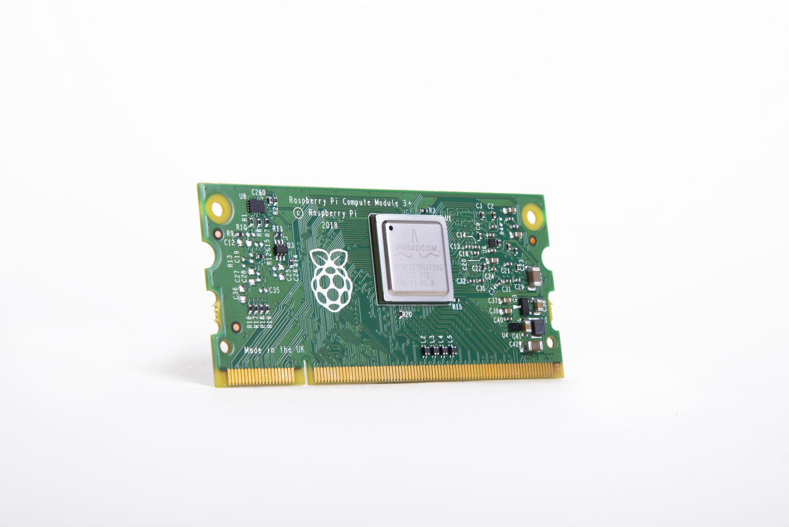
Raspberry Pi Compute Module 3+
Packed in a similar 67.6 x 31mm SODIMM styled module, the new compute module is built around the same Broadcom BCM2837B0 processor that is used on the Raspberry Pi 3, Model B+ and A+ boards but unlike the Model B+ and A+, the processor speed is clocked at 1.2GHz found on the previous compute module rather than the speedier 1.4GHz, and this decision is believed to be related to power supply limitations. Just like it’s predecessor, the CM+ continues to offer 1GB of LPDDR2 RAM and lacks the RPI 3 modules built-in WiFi and Bluetooth radios.
“…Compute Module 3+ is an evolution of Compute Module 3 and [original] Compute Module, bringing new features while keeping the form factor, electrical compatibility, price point, and ease of use of the earlier products.”—James Adams, COO Raspberry Pi Trading
One major upgrade for the CM+ is the better thermal control. To overcome the heating issues, it has refined the thermal control system. So long lasting processing is an utmost feature of Pi compute Module 3+. In opting for the best feature for business and industry purpose, perhaps this is a first requirement to have increased thermal capacity.
“The Compute Module also provides more interfaces than the regular Raspberry Pi, supporting two cameras and two displays, as well as extra GPIO.”
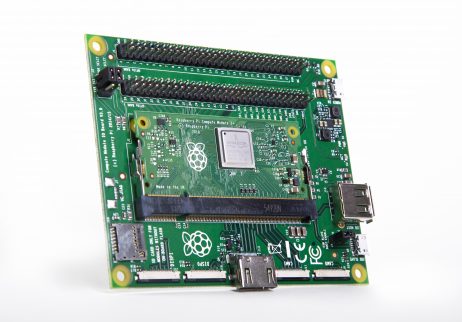
Raspberry Pi Compute Module 3+ Development Kit
Raspberry also offers a development kit which is expected to be open source. The refreshed development kit will include 1 × Lite and 1 × 32GB Compute Module 3+ modules, along with the Compute Module IO board, camera, and display adapters, jumper wires, and a programming cable.
The Raspberry Pi Compute Module 3+ is available in the following configurations: Lite/no eMMC ($25), 8GB eMMC ($30), 16GB ($35), and 32GB ($40). More information may be found at the Raspberry Pi Foundation’s RPi CM3+ announcement and datasheet, and the Newark Element14 CM3+ shopping page. More on the dev kit may be found at the CM3+ Development Kit product page.
Weather stations are interesting projects for beginners and very useful for expert makers. They are usually quite simple to build but also provide fairly accurate and useful weather data. We have built a couple of them in different tutorials on this website, with the difference usually being, the combinations and sometimes the accuracy of the sensors used. For today’s tutorial, we will build another weather station, but this time, we will use the BMP280 sensor as the primary one and we will be able to monitor temperature, atmospheric pressure, and altitude.
The BMP280 is the next-generation sensors from Bosch and it is an upgrade to their previous range of sensors including the BMP085, BMP180, and the BMP183. The BMP280 is great for all sorts of weather sensing with a low altitude noise of 0.25m and the same fast conversion rate as the previous sensors. In addition, the BMP280 can be used in both I2C and SPI mode and the sensor board version from Adafruit has a 3.3v voltage regulator and level shifter on board which means it can be used with either 3.3v or 5v voltage supply.
Weather stations are interesting projects for beginners and very useful for expert makers. They are usually quite simple to build but also provide fairly accurate and useful weather data. We have built a couple of them in different tutorials on this website, with the difference usually being, the combinations and sometimes the accuracy of the sensors used. For today’s tutorial, we will build another weather station, but this time, we will use the BMP280 sensor as the primary one and we will be able to monitor temperature, atmospheric pressure, and altitude.
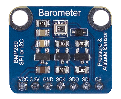
BMP280 Sensor board
The BMP280 is the next-generation sensors from Bosch and it is an upgrade to their previous range of sensors including the BMP085, BMP180, and the BMP183. The BMP280 is great for all sorts of weather sensing with a low altitude noise of 0.25m and the same fast conversion rate as the previous sensors. In addition, the BMP280 can be used in both I2C and SPI mode and the sensor board version from Adafruit has a 3.3v voltage regulator and level shifter on board which means it can be used with either 3.3v or 5v voltage supply.
Along with the BMP280, we will use the I2C-based, 128×32 OLED from Adafruit to show the values obtained from the BMP280 sensor. At the end of today’s tutorial, you would know how to use the BMP280 or any other i2c device with the Arduino and also know how to display data on an OLED display using the Arduino.
Required Components
The following components are required to build this project;
The exact components used for this tutorial can be bought via the link attached to each of the components above.
Schematics
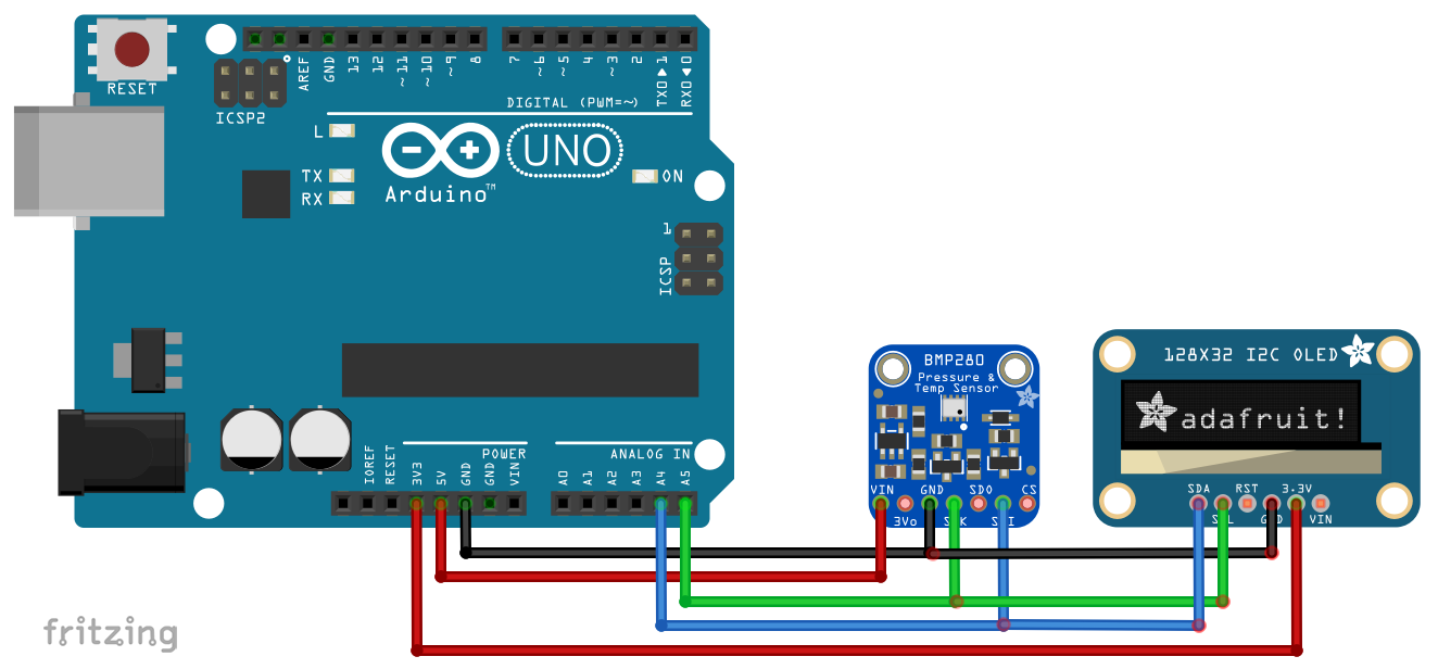
The schematic for this project is quite easy. The 128×32 OLED and the BMP280 both communicate with the Arduino via I2C, this means, they will be connected to the same pins (I2C) on the Arduino. Connect the components as shown in the schematics below.
Schematics
To make the connections easier to follow, here is a pin map showing how each of the components connects to the Arduino.
Arduino – BMP280
5V - vin
GND - GND
A4 - SDA
A5 - SCL
Arduino – OLED
3.3V - 3.3V
GND - GND
A4 - SDA
A5 - SCL
Go over the schematics once more to ensure everything is properly connected.
Code
To write the code for this project, we will use three key libraries; the Adafruit BMP280 library, the Adafruit GFX library and the Adafruit SSD1306 library. The three libraries can be downloaded via the Arduino Library Manager or via the download link attached to them.
The Adafruit BMP280 contains functions that make it easy to write the code that will obtain the parameters from the sensor while the Adafruit GFX and SSD1306 libraries are used to easily display texts and graphics on the OLED.
I will do a run through of the entire code and will try to explain as much as possible.
We start the code by including the libraries that we will use on the project after which we specify the dimensions (width = 128, height =32) of the OLED display and declare the pin of the Arduino to which the reset pin of the OLED is connected.
Next, we create a class of the OLED library with the dimensions as arguments and also create a class of the BMP280 library.
Adafruit_SSD1306 display(SCREEN_WIDTH, SCREEN_HEIGHT, &Wire, OLED_RESET); //Declaring the display name (display)
Adafruit_BMP280 bmp;
Next, we write the void setup() function. We start by initializing the BMP using the bmp.begin() command and we also start communications with the OLED using the display.begin() function to get it started.
void setup() {
  bmp.begin();                                //Start the bmp
  display.begin(SSD1306_SWITCHCAPVCC, 0x3C); //Start the OLED display
With the initializations done, we set the color (using display.setTextColor function), set the font size (using the display.setTextSize() function), and display a welcome message (using the display.print() function). Feel free to change the displayed text as desired
display.clearDisplay();
  display.display();
  display.setTextColor(WHITE);
  display.setTextSize(1);
  display.print("SurtrTech");     //Show the name, you can remove it or replace it
  display.setCursor(32,12);
  display.setTextSize(2);
  display.println("BMP280");
  display.display();
  delay(2000);
}
With this done, we move to the void loop function(). We start by clearing the display (using the display.clearDisplay() function) after which we read the temperature, pressure and altitude, storing them into the variables T, P, and A respectively.
void loop() {

    display.clearDisplay();
    float T = bmp.readTemperature();           //Read temperature in C
    float P = bmp.readPressure()/100;         //Read Pressure in Pa and conversion to hPa
    float A = bmp.readAltitude(1019.66);      //Calculating the Altitude, the "1019.66" is the pressure in (hPa) at sea level at day in your region
Next, we display the measured parameters using the display.setCursor() function to effectively divide the OLED screen so they are all displayed at once. After this, we use the display.display() function to apply changes on the OLED. A time delay of 2000ms is set to ensure the values stay long enough on the display to be seen before they are replaced by new values.
display.setCursor(0,0);                   //Oled display, just playing with text size and cursor to get the display you want
    display.setTextColor(WHITE);
    display.setTextSize(2);
    display.print("Temp");

    display.setCursor(0,18);
    display.print(T,1);
    display.setCursor(50,17);
    display.setTextSize(1);
    display.print("C");

    display.setTextSize(1);
    display.setCursor(65,0);
    display.print("Pres");
    display.setCursor(65,10);
    display.print(P);
    display.setCursor(110,10);
    display.print("hPa");

    display.setCursor(65,25);
    display.print("Alt");
    display.setCursor(90,25);
    display.print(A,0);
    display.setCursor(110,25);
    display.print("m");

    display.display();
    delay(2000);
}
The complete code for the project is provided below and also attached under the download section of the tutorial.
#include <Adafruit_GFX.h>      //Libraries for the OLED and BMP280
#include <Adafruit_SSD1306.h>
#include <Adafruit_BMP280.h>

#define SCREEN_WIDTH 128 // OLED display width, in pixels
#define SCREEN_HEIGHT 32 // OLED display height, in pixels
#define OLED_RESET    -1 // Reset pin # (or -1 if sharing Arduino reset pin)

Adafruit_SSD1306 display(SCREEN_WIDTH, SCREEN_HEIGHT, &Wire, OLED_RESET); //Declaring the display name (display)
Adafruit_BMP280 bmp;

void setup() {
  bmp.begin();                                //Start the bmp
  display.begin(SSD1306_SWITCHCAPVCC, 0x3C); //Start the OLED display
  display.clearDisplay();
  display.display();
  display.setTextColor(WHITE);
  display.setTextSize(1);
  display.print("SurtrTech");     //Show the name, you can remove it or replace it
  display.setCursor(32,12);
  display.setTextSize(2);
  display.println("BMP280");
  display.display();
  delay(2000);
}

void loop() {

    display.clearDisplay();
    float T = bmp.readTemperature();           //Read temperature in C
    float P = bmp.readPressure()/100;         //Read Pressure in Pa and conversion to hPa
    float A = bmp.readAltitude(1019.66);      //Calculating the Altitude, the "1019.66" is the pressure in (hPa) at sea level at day in your region
                                              //If you don't know it just modify it until you get the altitude of your place

    display.setCursor(0,0);                   //Oled display, just playing with text size and cursor to get the display you want
    display.setTextColor(WHITE);
    display.setTextSize(2);
    display.print("Temp");

    display.setCursor(0,18);
    display.print(T,1);
    display.setCursor(50,17);
    display.setTextSize(1);
    display.print("C");

    display.setTextSize(1);
    display.setCursor(65,0);
    display.print("Pres");
    display.setCursor(65,10);
    display.print(P);
    display.setCursor(110,10);
    display.print("hPa");

    display.setCursor(65,25);
    display.print("Alt");
    display.setCursor(90,25);
    display.print(A,0);
    display.setCursor(110,25);
    display.print("m");

    display.display();
    delay(2000);
}
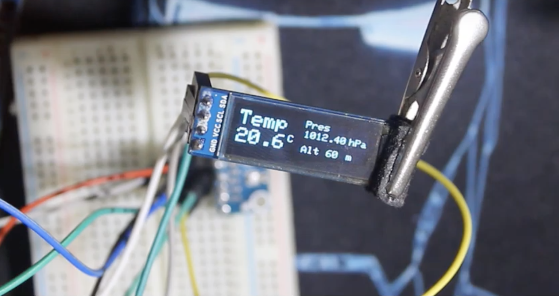
Demo
Go over the setup in the schematics to ensure you connected everything as described then upload the code to your Arduino. You should see the display come as shown in the image below after a while.
That’s all guys. Are you working on a quadcopter and want to add an additional sensor to determine altitude or you are just building a standard weather station and you need to add temperature and pressure, this might just be the sensor for you.
Feel free to reach out via the comment section if you have any difficulty getting things to work.
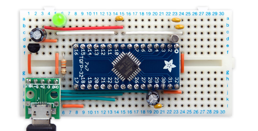
This project describes how to build an ATSAMD21-based computer on a prototyping board using the minimum number of components, and program it from the Arduino IDE. David Johnson-Davies writes:
I give two alternative methods of uploading a bootloader to the bare ATSAMD21 chip using the Arduino IDE. You can then program the minimal ATSAMD21 computer from the Arduino IDE via the USB port, like any other Arduino board.
If you’re looking for something more powerful than the ATmega328 in the Arduino Uno a good choice is the ATSAMD21. This is an ARM Cortex M0+ processor with up to 256 KB flash memory, 32 KB RAM, and a 48 MHz clock, so it’s substantially better equipped than the ATmega328. In addition it has a USB interface built in, so there’s no need for a separate chip to interface to the serial port.
Minimal ATSAMD21 Computer is Arduino compatible – [Link]
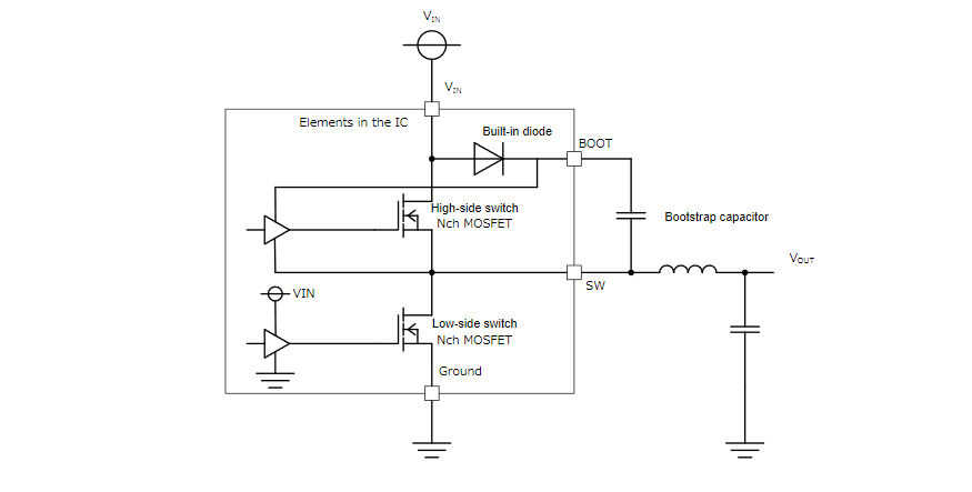
This application note explains the step-up circuit using a bootstrap capacitor. In buck converters, this circuit is used when the high-side switch is the N-ch MOSFET.
The configuration of the circuit in proximity to a buck converter depends on the polarity of the high-side switch.When a P-ch MOSFET is used for the high-side switch, there are advantages over using a N-ch MOSFET, such as the capability of driving the switch with input voltage VINas the gate voltage, as well as voltage reduction and obtainment of the maximum duty. On the contrary, the use of a P-ch MOSFET requires a larger chip area for passing the same current.The use of an N-ch MOSFET for the high-side switch requires a gate voltage of VIN+ Vth (threshold voltage of the N-ch MOSFET) or higher. A step-up circuit is required because the gate voltage is higher than VIN. This circuit is configured with an internal diode and an external bootstrap capacitor (charge pump type). The total cost, including the cost of the external bootstrap capacitor, can be lowered because the chip area can be reduced compared with the P-ch MOSFET, as mentioned above.
Bootstrap Circuit in the Buck Converter explained – [PDF]
The emerging trend of smart lighting and Internet of Things, requires a new generation of LED drivers. InfineonTechnologies AG introduces the new member of its XDP LED series, the XDPL8221 for cost-effective dual-stage drivers with advanced features. This device combines a quasi-resonant PFC and a quasi-resonant flyback controller with primary side regulation together with a communication interface. A comprehensive set of configurable protection mechanisms (standard and sophisticated) ensure safe, reliable and robust LED driver for a large set of use cases. The new driver IC will be showcased at the APEC 2019 exhibition in Anaheim, CA.
The XDPL8221 combines advanced functions, such as multi control featuring constant voltage, constant current and limited power as configurable operating parameters. The result is a versatile, high performance LED driver.
The performance of the XDPL8221 helps to design more efficient devices. This driver IC supports full functionality for both AC and DC input in the nominal input voltage range of 100 VAC to 277 VAC or 127 VDC to 430 VDC. Depending on the actual situation, the built-in digital control selects the best mode of operation. It can switch between quasi-resonant, discontinuous conduction or active burst modes.
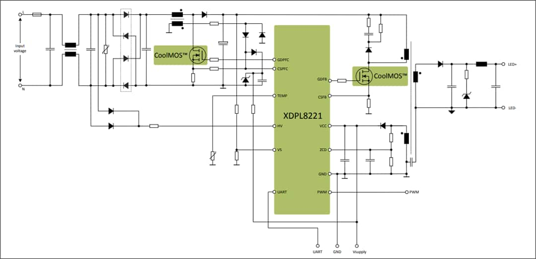
XDPL8221 Typical Application Circuit
The XDPL8221 FB can be configured to operate in Constant Voltage (CV), Constant Current (CC) or Limited Power (LP) mode offering a large degree of flexibility.
The XDPL8221 UART interface with a command set enables control of the functions of the device and provides status information. This enables numerically exchanged real-time data. This data can be used for monitoring or additional local control functions.
This driver IC can be dimmed flicker free below one percent, while the current is still regulated with a high accuracy. The chip also offers a dim-to-off function to keep the device in a standby mode when the light is off with a low standby power (less than 100 mW, depending on driver design).
Reduced bill of materials (BOM) and increased flexibility minimize the overall system cost. The XDPL8221 comes in a DSO-16 package and, with a wide tool support, it is easy to design-in. This accelerates the design cycle and shortens time-to-market.
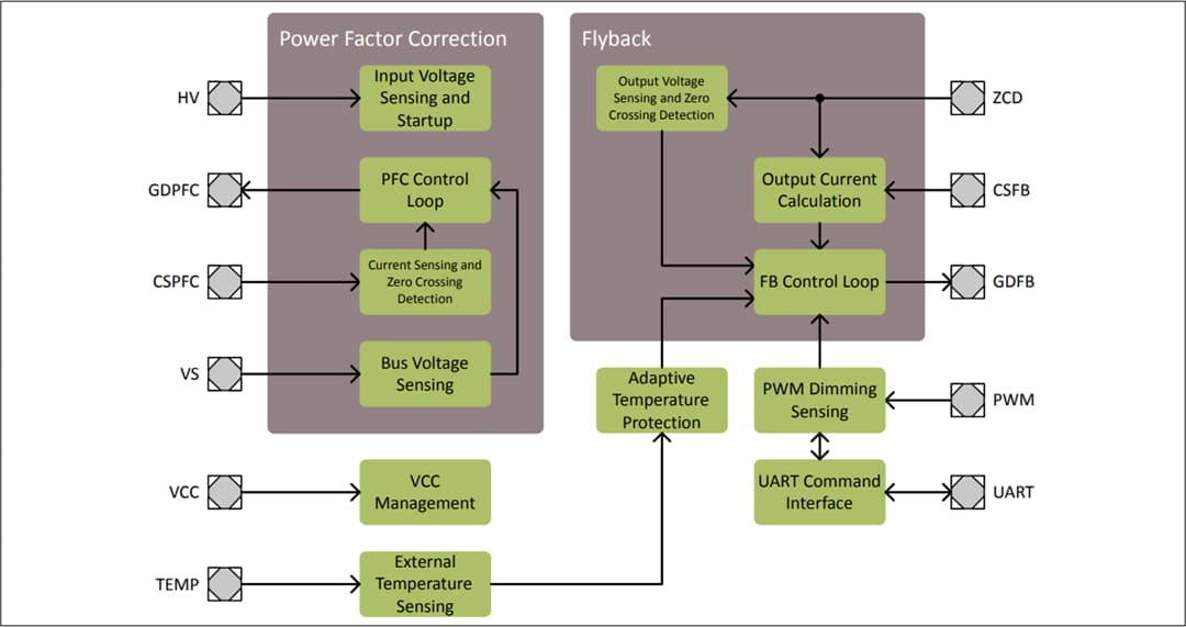
XDPL8221 Function Block Diagram
Features
UART interface to control driver output and reading operating status
Flicker-free output dimming by analog reduction of driving current down to 1%
Integrated two stage digital controller allows a reduced number of external parts, optimizes Bill of Materials (BOM) and form factor
Two-stage design eliminates AC ripple on output
Supports universal AC and DC input voltage (90Vrms to 305Vrms) nominal
High efficiency up to 90%
Multi-control output
Constant Current (CC)
Constant Voltage (CV)
Limited Power (LP)
Performance and protection related driver parameters are configurable via UART interface allowing for design flexibility and optimization
Low harmonic distortion (Total Harmonic Distortion (THD) <15%) down to 30% nominal load
Integrated 600V high voltage start-up cell ensures fast time to light (<250ms)
Configurable Adaptive Temperature Protection
Automatic switching of the Power Factor Correction (PFC) between Quasi-Resonant Mode (QRM) and Discontinuous Conduction Mode (DCM)
Automatic switching of the Flyback (FB) between QRM, DCM and Active Burst Mode (ABM)
Pulse Width Modulation (PWM) dimming input
Comprehensive set of protection features with configurable reaction like auto-restart or latch
Output over-voltage protection (open load)
Output under-voltage protection (output short)
VCC over- and under-voltage lockout
Input over- and under-voltage protection
Bus over- and under-voltage protection
Over-current protection for both PFC and FB stages
Package
PG-DSO-16
10mm x 4mm
Applications
Flicker free LED driver for indoor or outdoor applications
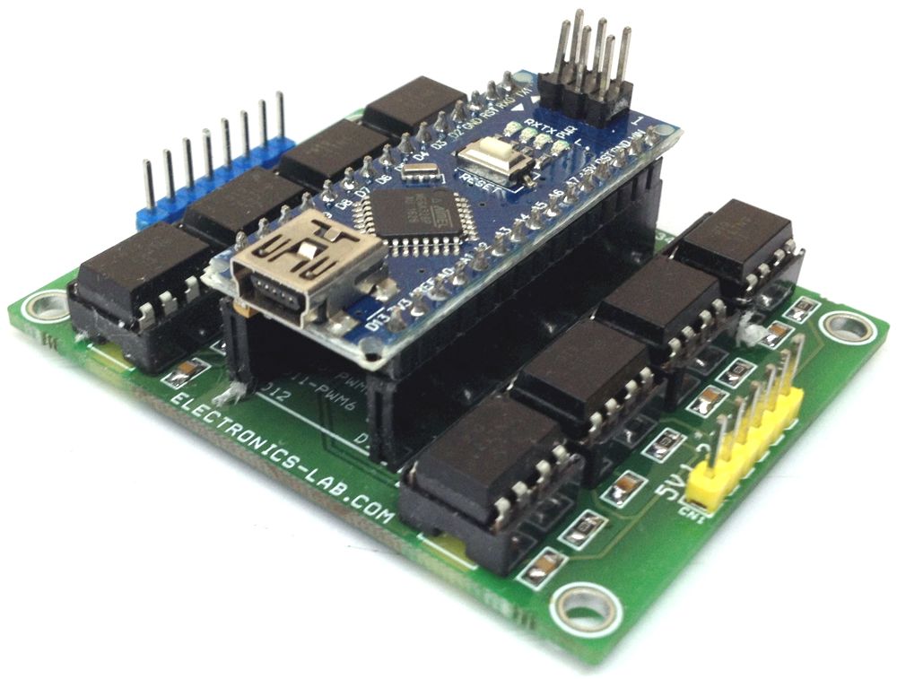
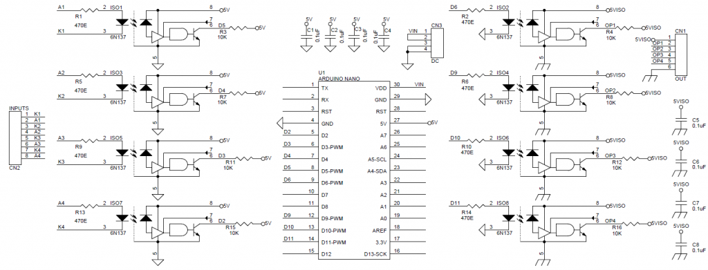
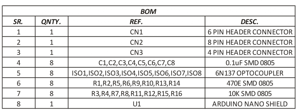
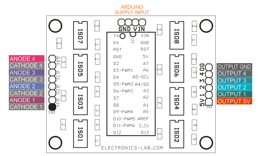
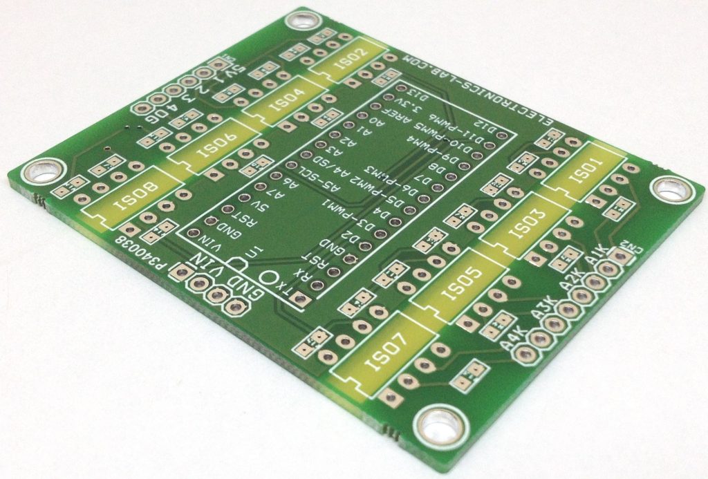
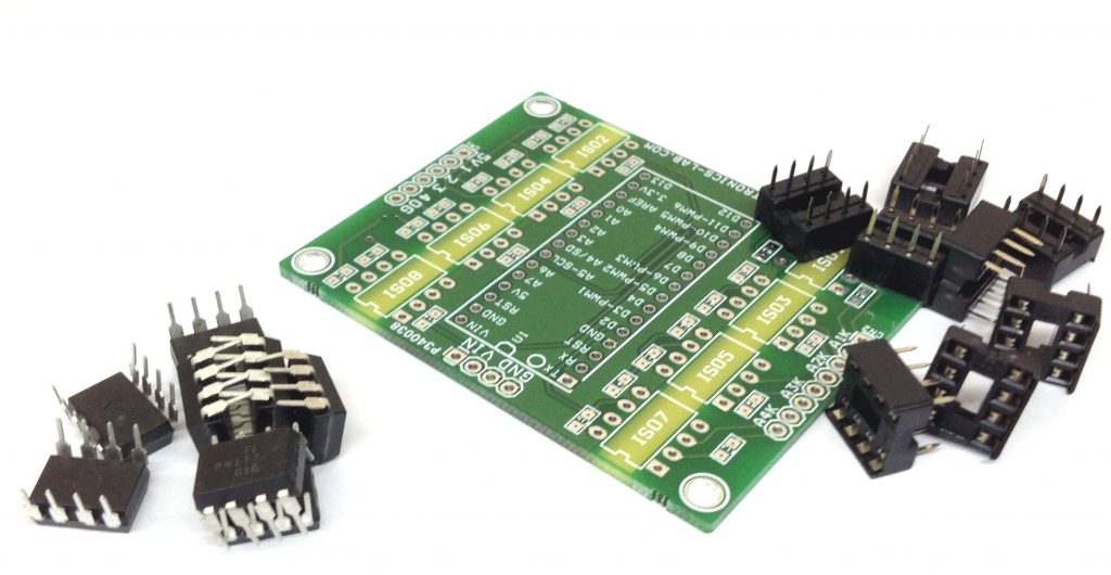
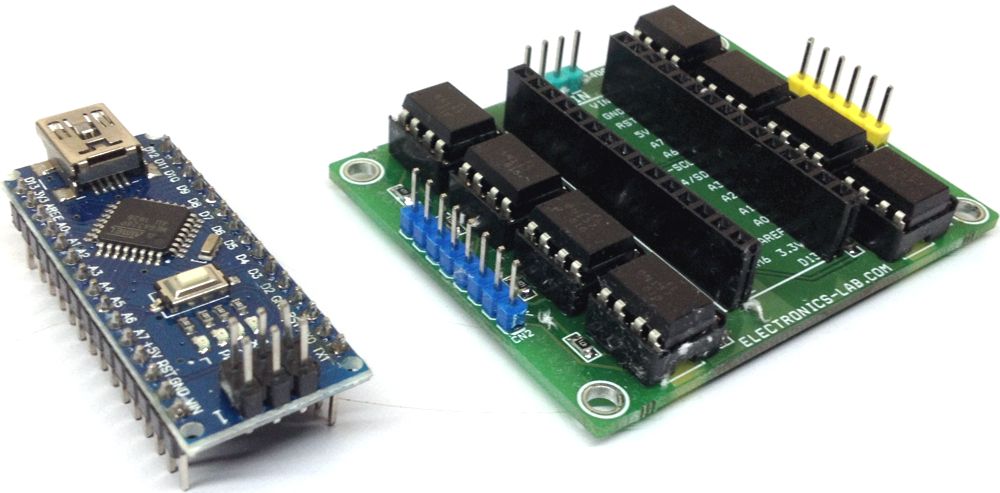
This shield enables you to interface many different devices to Arduino Nano using optically isolated inputs/outputs. The circuit consists of 4 Input channels and 4 Output channels and all 8 I/O lines are optically isolated. This project can help in various industrial applications where EMI noise and high voltage lines can damage the Arduino Nano or other circuits connected to it. Circuit is built using 8 x 6N137optocoupler. The 6N137 optocoupler can switch at frequency up to 10 MHz.
This shield enables you to interface many different devices to Arduino Nano using optically isolated inputs/outputs. The circuit consists of 4 Input channels and 4 Output channels and all 8 I/O lines are optically isolated. This project can help in various industrial applications where EMI noise and high voltage lines can damage the Arduino Nano or other circuits connected to it. Circuit is built using 8 x 6N137optocoupler. The 6N137 optocoupler can switch at frequency up to 10 MHz.
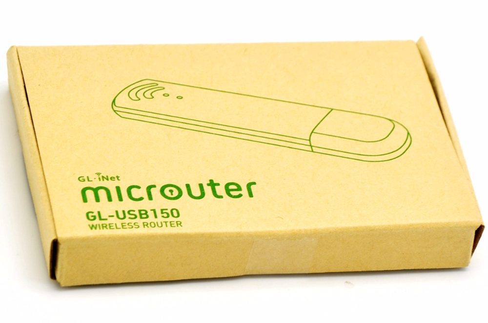
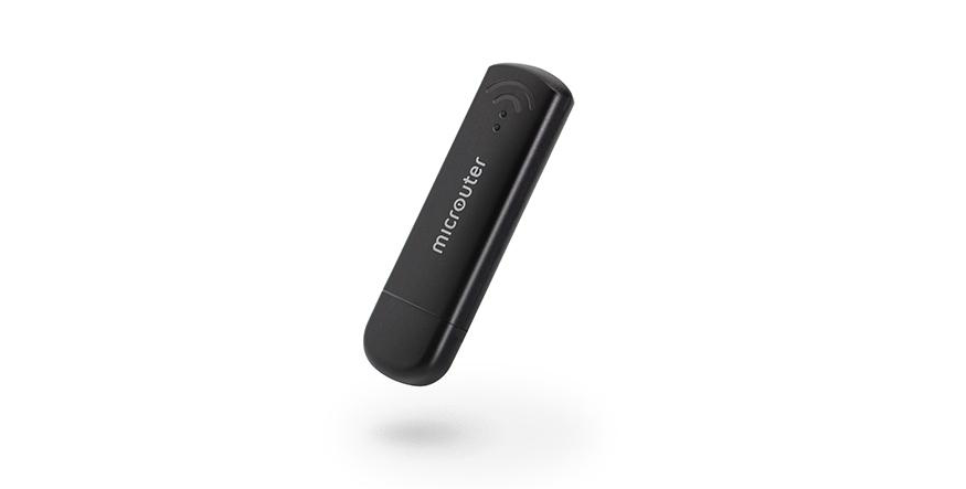
Micro routers are portable USB mini routers used for cyber privacy or as access points. They are easy plug and play devices. GL.inet has introduced a low-cost micro router based on OpenWRT. The GL-USB150 micro router comes with the Qualcomm QCA9331 CPU, MIPS processor with the speed of 400 MHz, 64 MB DDR3 Ram is installed for system memory purpose. While the system storage is given 4 MB, that is a NOR flash type.
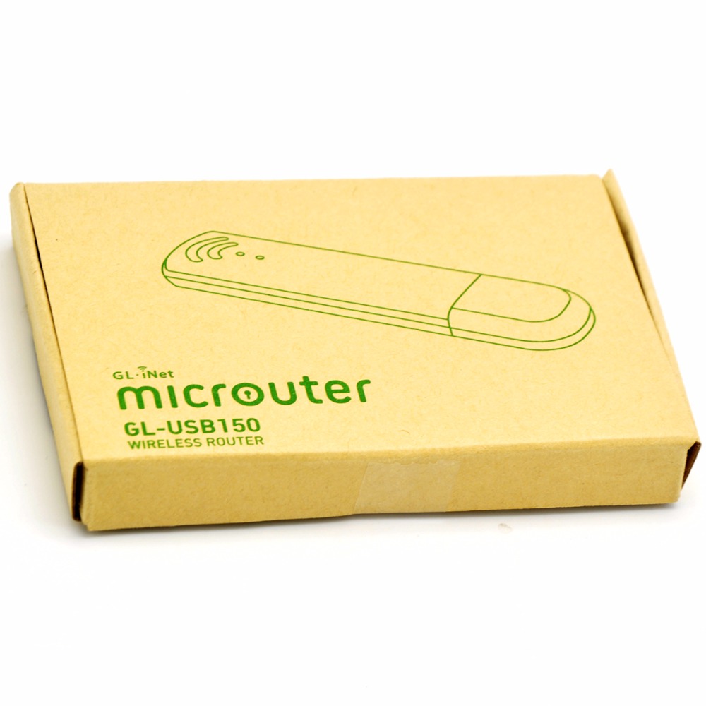
GL-USB150 Micro Router
WiFi connectivity transmission rate is 150 Mbps at 2.4 GHz band with version 802.11 b/g/n. It is ready to be used with any USB port. Power is supplied via the USB port with standard 5V/1A, and power consumption less than 1 W. That’s even lower than counterpart routers of the same caliber.
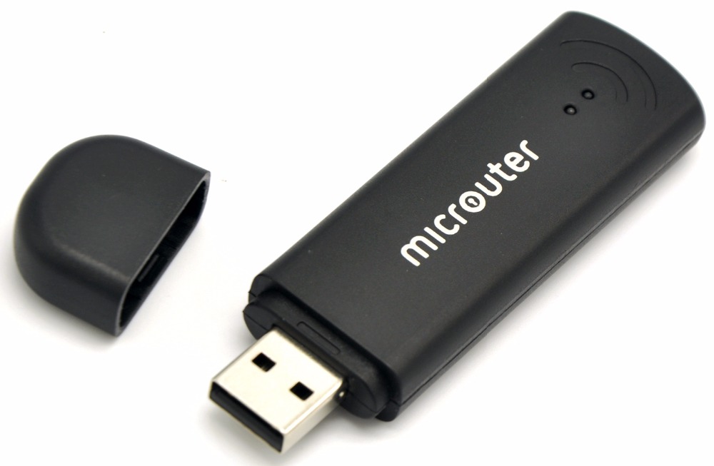
GL-USB150 Micro Router
Though the structure is minimized, which gives a lot of advantages in making it fit, on the other side, it has a few limitations. These limitations come in the shape of customization. Unlike other routers, this small router cannot be customized with additional extensions. There is no Ethernet port or extra USB port available. Just a USB port is enough to get on with its functionality. The USB port of power banks can also be used, as it only needs standard power input. Whether if you are running a computer or laptop with USB port, or portable USB power bank and charger, it can be plugged into a standard USB port.
GL-USB150 micro router specifications
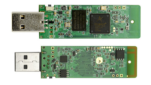
CPU – Qualcomm QCA9331 (Atheros AR9331) MIPS processor @ 400MHz
System Memory – 64MB DDRII
Storage – 16MB NOR Flash
Connectivity – 2.4GHz 802.11b/g/n WiFi up up 150Mbps transmission rate
Power input – 5V/1A via USB port
Power consumption – <1W
Dimension – 82x24x11mm
Weight – 10 grams
There is no need to download and install drivers to make it compatible with every device you connect it to. Pre-installed OpenWRT gives freedom from that hectic work. OpenWRT software will make it plugged in as Linux OS, that is ready to be used. Slim and smart routers are the future. With the advancement in software and operating system, comes advancement in connectivity and power consumption as well.
GL-USB150 Micro Router Inside
Upon its connection to the computer via a USB port, it will work as a USB ethernet adapter automatically directing the user’s traffic through (I smell something here). Primary internet connection can be changed over to it very easily. In case the user wants to use a different WIFI connection, then no need to plug it off. Just keep it plugged in a while changing the connectivity to the secondary one.
When inserted into a Windows or Linux computer it boots to Linux then registers itself to the host (your client’s) computer as a USB Ethernet device. It becomes the default route to the network. This causes the PC to direct all it’s traffic through this device as opposed to the WiFi or Ethernet it was intended to be using. The router then joins a predetermined WiFi access point which it uses as it’s path to the Internet.
By setting this router to be accessible via the Tor Network you can access it remotely, usually even if the router is deployed behind a firewall or cable modem.
Although the device looks small, it’s a potential tool for the unjust hacker. As demonstrated by Mason Jeffers, the micro-router can be used as a penetration tool and with is USB Pendrive lookalike shape, it can easily camouflage as a standard flash drive to the unknown host. Imagine plugging this to a server, or some critical infrastructure, it can easily be used to maintain a backdoor into a network system.
This means you can walk into any your customer’s building and just push a small innocent looking USB device into a computer then watch and manipulate it’s traffic from the comfort of your home. You would also have access to a full blown Linux box in this network which you could use to mount any number of attacks.
This lightweight and easy to use micro router GL-USB150 is now available for purchase for $29 at Amazon and AliExpress. It comes open source and programmable in OpenWRT. More information is available on the product page.