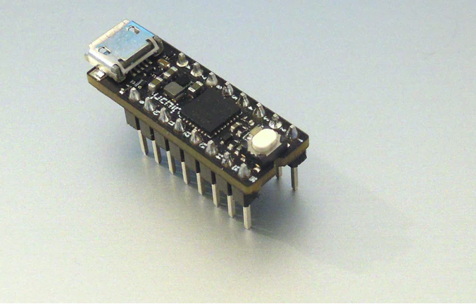
A very small narrow-DIP-sized, Arduino Zero compatible USB dev board (OTG enabled), with integrated buck and boost power supplies!
The Arduino ecosystem provides an invaluable resource of hardware and software, which allows quick development of a myriad of projects thanks to its fruitful community.
Several Arduino-compatible boards came out in the past years, to increase the versatility or to reduce the size of the original Arduino boards. However, in our opinion this has not come without compromises.
Some cheap boards, while being small enough, lack of a proper integrated power supply. In other words, the developer has to implement it externally, reducing the benefits of low cost and small size. In other cases, linear regulators are used, making them unsuitable for low power applications or when you need to provide a decent amount of current for the external circuitry.
Other boards use microcontrollers with limited memory, pin count or peripheral set, which make them unsuitable for more complex applications.
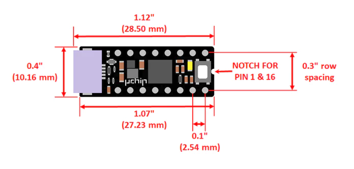
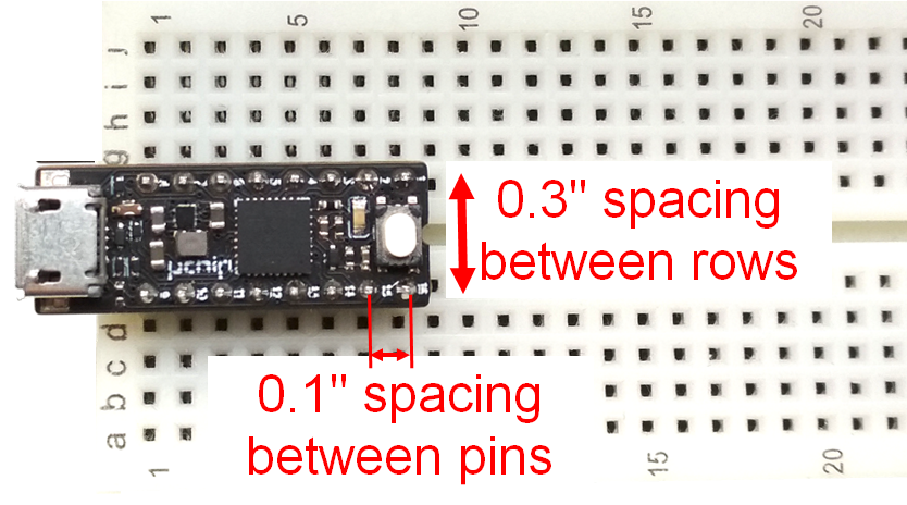
And finally, some boards are not breadboard compatible, and, to date no Cortex M0+ board features 0.3” spacing between rows, wasting precious breadboard space.
We wanted a device that solved all these problems without compromises.
Then we came up with our idea! We wanted a dev board:
USB based, capable of being programmed without requiring expensive external programmers, just like Arduino and many other dev boards.
With a powerful microcontroller with plenty of RAM and FLASH.
With a rich set of peripheral.
Capable of acting both as an USB host and Device.
With integrated buck and boost power supplies.
USB- or externally-powered.
Capable of providing an external programmable (3.3V or 5V) high-current power supply, when powered by USB.
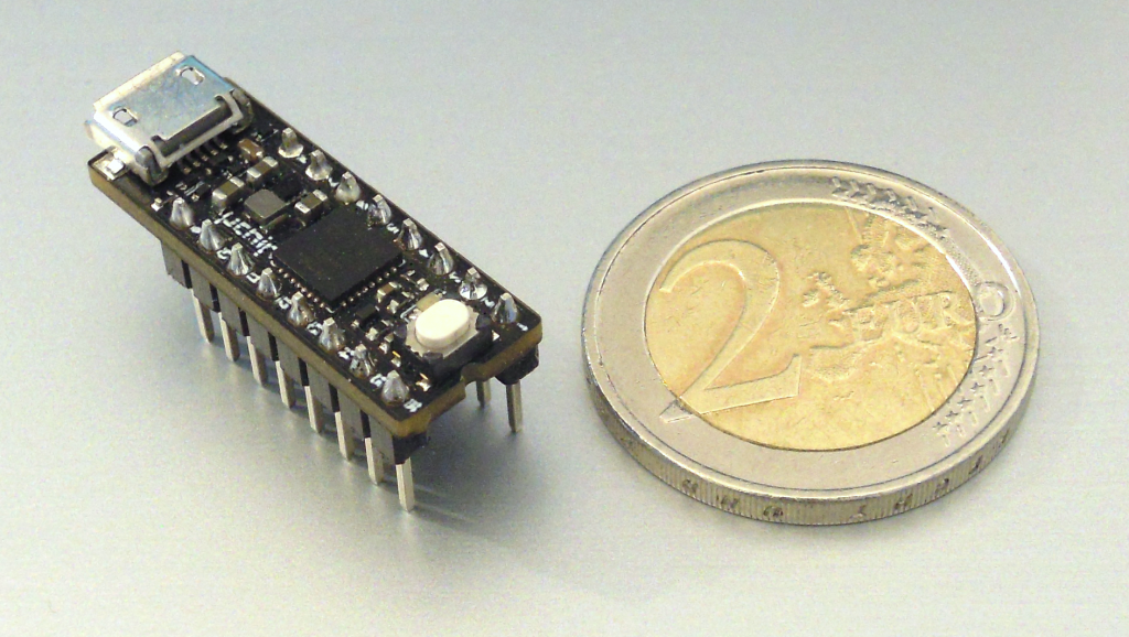
Breadboard compatible, with a narrow DIP footprint (0.3” spacing).
And, of course, low cost.
We worked hard, to optimize everything, and our result is uChip!
Dimensions
Specifications
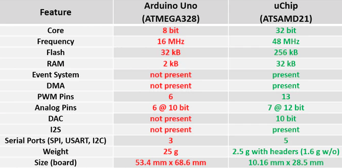
CPU: 32-bit Cortex M0+ ATSAMD21-series running at 48 MHz (Arduino Zero Compatible)
FLASH: 256 kB (248 kB due to integrated bootloader).
RAM: 32 kB, zero wait states.
Powered via USB or externally (3.3V to 5V).
Integrated 500-mA boost and 1-A buck converters and automatic power switching circuitry.
Each converter can also be individually turned off, e.g. if you want to force power draw exclusively from external pins (self-powered device), or if you want to turn off an external USB device connected with a micro A cable.
When powered through the USB port, the output voltage on the power pins can be selected via software to be either 3.3V or the USB voltage (typically 5V +/- 10%).
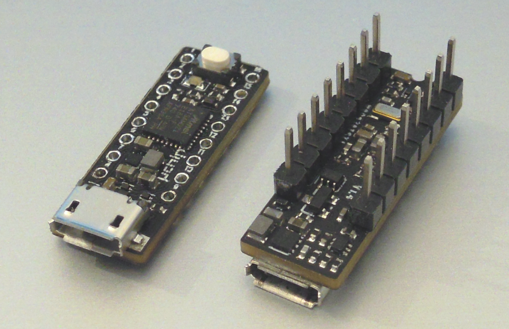
14 I/O pins (2 of them can be used to connect an external SWD programmer/debugger) and 2 power pins (VCC and GND).
Status LED (it can be turned on/off via software using a single instruction).
Multi function push button for reset/program.
7 12-bit ADC inputs.
10-bit DAC output.
14 external interrupt input pins.
Up to 5 serials between SPI, I2C and UART.
I2S port for audio decoders such as UDA1334A.
13 PWM pins.
Size: 28.5 mm x 10.16 mm (1.1 “ x 0.40 “), including USB port protrusions (27.23 mm x 10.16 mm excluding USB)
Pinout standard logic CMOS compatible: power and GND are on pin 16 and 8, so you can also emulate some 16 pin CMOS ICs (4000 and 74HC series)!
Low cost! (13.6€ per board for 10 pieces or 20€/board!).
uChip on breadboard
Comparison with Arduino Uno!
The project will be open-source, included all the examples we showed here! The schematics, gerbers, as well as sources will be released online, to allow you and the community to develop shields, applications, projects, and, why not, improve it!
The project is on www.kickstarter.com but it is not live yet. It will be launched on 10 March. Feel free to leave your feedback on the corresponding page.
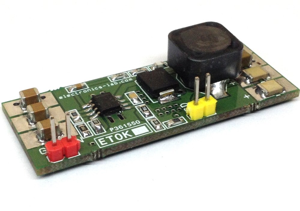
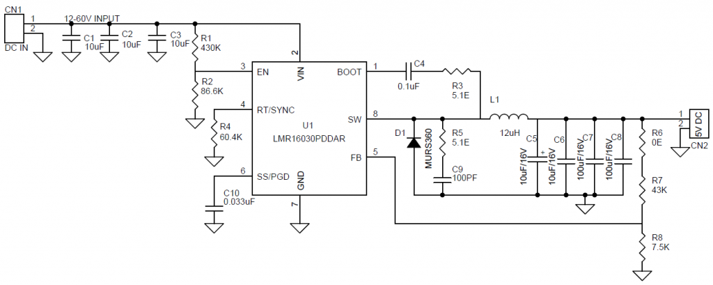
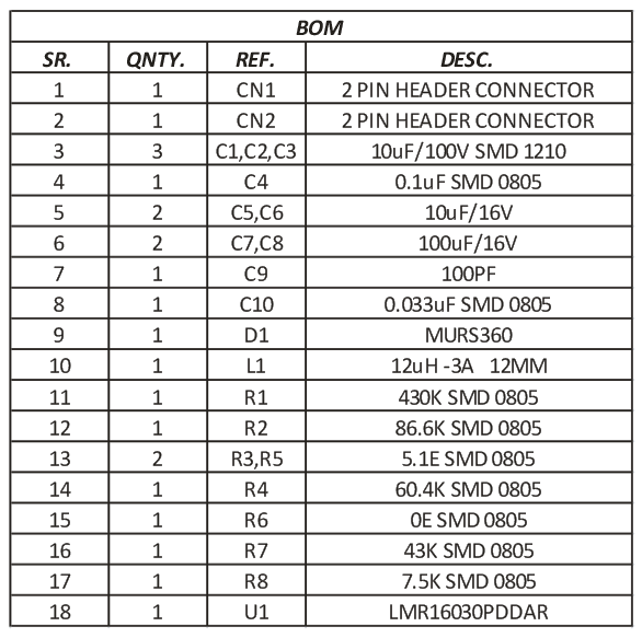
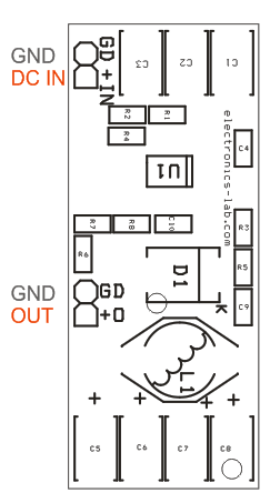
The circuit published here is a compact 60V DC-DC Step down Converter that provides 5V DC output and load current up to 3A in compact size. The project is based on LMR16030.
The LMR16030 is a 60 V, 3 A SIMPLE SWITCHER® step down regulator with an integrated high-side MOSFET. With a wide input range from 4.3 V to 60 V, it’s suitable for various applications from industrial to automotive for power conditioning from unregulated sources. The regulator’s quiescent current is 40 µA in Sleep-mode, which is suitable for battery powered systems.
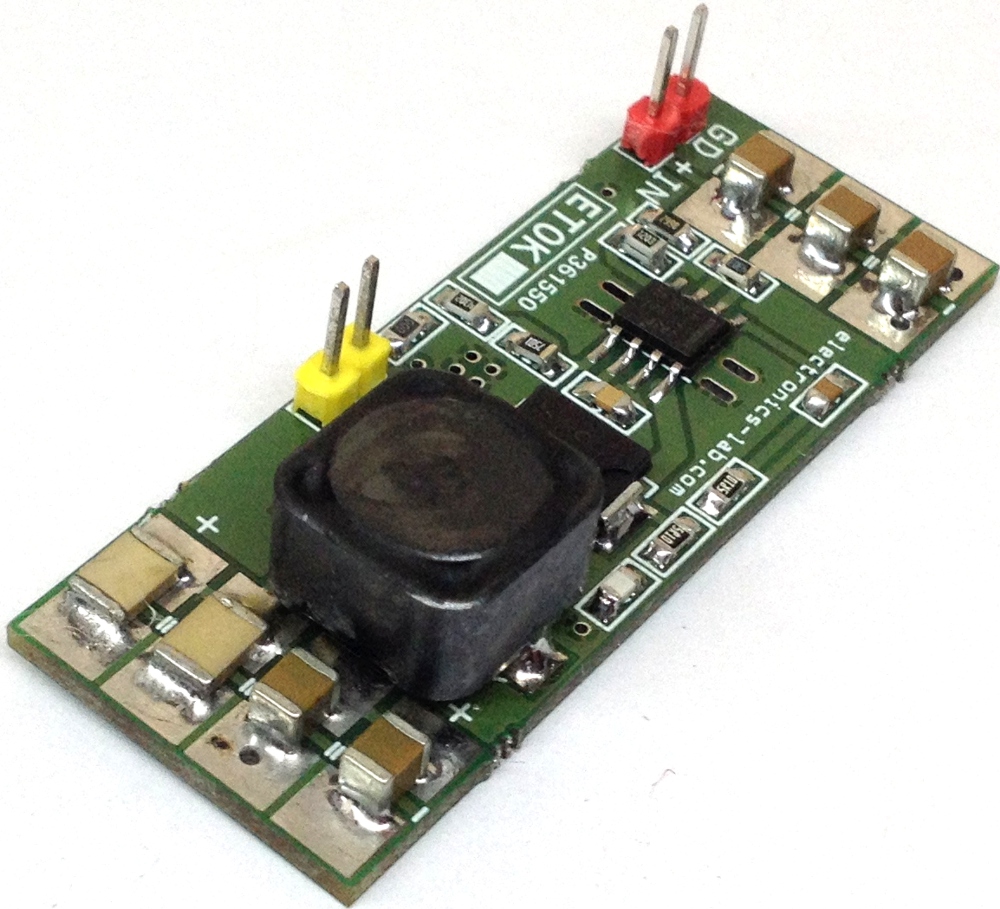
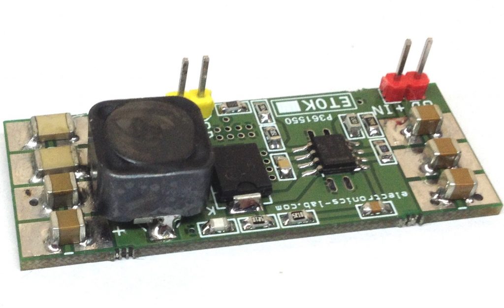
60V to 5V DC-DC Step-Down Converter using LMR16030 – [Link]
The circuit published here is a compact 60V DC-DC Step down Converter that provides 5V DC output and load current up to 3A in compact size. The project is based on LMR16030.
The LMR16030 is a 60 V, 3 A SIMPLE SWITCHER® step down regulator with an integrated high-side MOSFET. With a wide input range from 4.3 V to 60 V, it’s suitable for various applications from industrial to automotive for power conditioning from unregulated sources. The regulator’s quiescent current is 40 µA in Sleep-mode, which is suitable for battery powered systems. An ultra-low 1 µA current in shutdown mode can further prolong battery life. A wide adjustable switching frequency range allows either efficiency or external component size to be optimized. Internal loop compensation means that the user is free from the tedious task of loop compensation design. This also minimizes the external components of the device. A precision enable input allows simplification of regulator control and system power sequencing. The device also has built-in protection features such as cycle-by-cycle current limit, thermal sensing and shutdown due to excessive power dissipation, and output over-voltage protection.
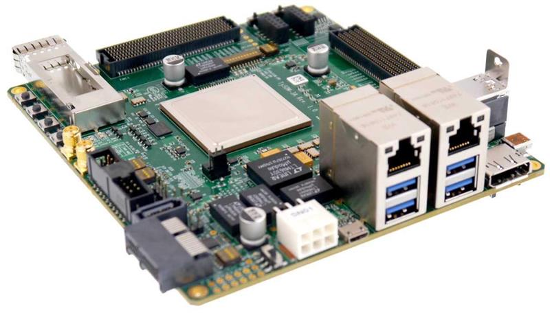
Aldec’s TySOM-3A-ZU19EG embedded system development board, showcased at Embedded World 2019, supports the early co-development and co-verification of hardware and software.
Aldec, Inc., a pioneer in mixed HDL language simulation and hardware-assisted verification for FPGA and ASIC designs, has launched the TySOM-3A-ZU19EG, to assist in the development of AI, Deep-learning Neural Network (DNN) and other applications dependent on complex algorithm acceleration in firmware.
This much-anticipated addition to Aldec’s popular family of embedded development kits showcased at Embedded World on booth4-560 in Hall 4, features a Xilinx Zynq® UltraScale+™ ZU19EG FFVB1517 MPSoC, which has more than 1 million logic cells, and a quad-core ARM® Cortex-A53 platform running at up to 1.5GHz. The kit provides 64-bit processor scalability while combining real-time control with soft and hard engines for SoC prototyping solution, IP verification, graphics, video, packet processing and early software development.
This latest addition to the Aldec TySOM range is our most powerful yet,” comments Zibi Zalewski, General Manager of Aldec’s Hardware Division, “and while it is suitable for the development of some of today’s most complex applications, such as AI and DNN, it is an extremely scalable solution, so remains a cost-effective proposition for small to mid-size SoC FPGA and ASIC prototyping. Few if any other platforms represent a similarly sound and long-term investment.
The TySOM-3A-ZU19EG is designed to provide flexibility when selecting peripherals, because of leveraging all the features of the Zynq UltraScale+.
The kit contains 8GB DDR4 SODIMM Memory for the Programmable Logic (PL) and 8GB DDR4 SODIMM Memory for the Processing System (PS). It also includes 2GB NAND memory, supports Micro-SD card storage, SATA storage and features a 512MB QSPI Flash Memory.
Communication/networking is enabled by 2x Gigabit Ethernet, Wi-Fi & Bluetooth, CAN, 4× USB 3.0, USB to UART Bridge, USB 2.0 OTG, JTAG USB, Pmod, QSFP+ and PCIe x1 GEN3/4 connectors.
Multimedia interfaces are provided using DisplayPort, HDMI IN/OUT. To expand the peripherals, 2× FMC HPC VITA 57.1-2010 compliant connectors are provided on the board; thus, additional devices can be connected as FMC Daughter Cards (available from Aldec plus other vendors).
more information: www.aldec.com (website has currently https configuration issues)
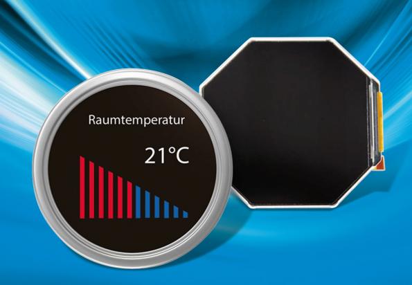
Tianma Europe’s TM033XDHG01 display module has been designed for use in applications such as thermometers, manometers where analogue displays are traditionally used.
With its high display brightness of 600 cd/m 2, a contrast ratio of 1:800 and a large colour space of 16.7 million colours, the TM033XDHG01 is well suited for outdoor use. The wide viewing angle of up to 80 degrees allows reading from almost any perspective. A built-in display controller with a MIPI-DSI interface enables customer-specific configurations with other interfaces. On request, the display module can also be equipped with a round PCAP controller to support gesture control. The 8.4cm wide octagonal frame simplifies mechanical installation in the front panel of devices.
Main characteristics:
Diagonal : 3.3”
Resolution : 320 x 320
Wide viewing angle (u/d/l/r) : 60°/70°/70°/70°
Luminance : 750 cd/m2
Backlight lifetime : 20 kh
more information on Tianma Europe GmbH – www.tianma.eu
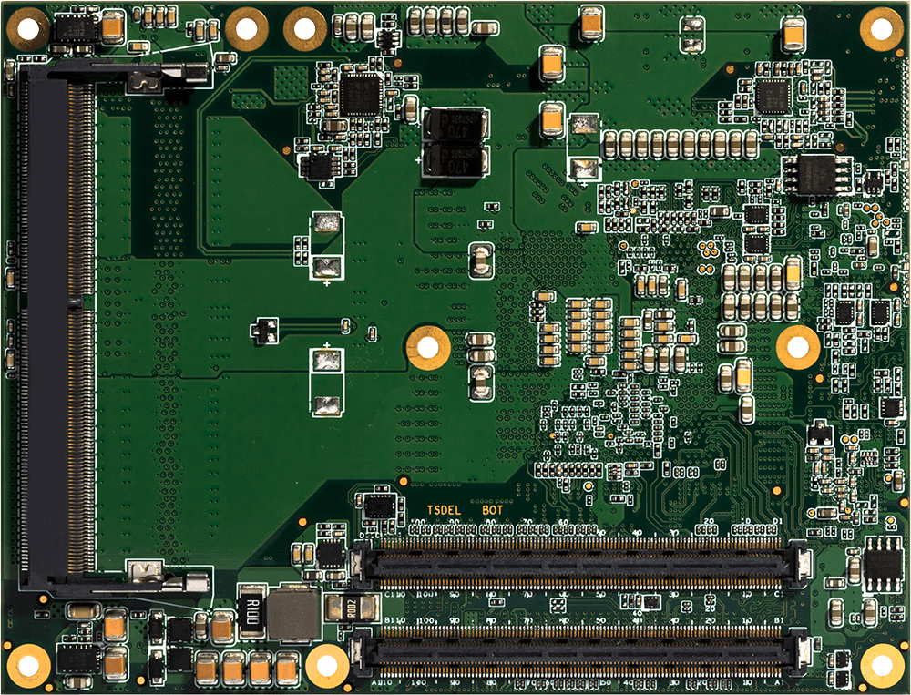
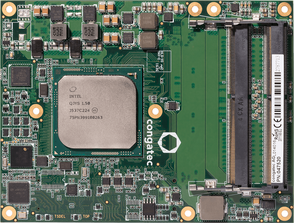
A new milestone is hit by Congatec, as they recently announced Type 7 modules. Congatec has struggled hard to take Linux friendliness to the very next level and to make server response to quickest possible till date. To do that, two Type 7 modules are introduced to the market which provide support of up to 96GB DDR4 and designed for converged edge servers in aircraft.
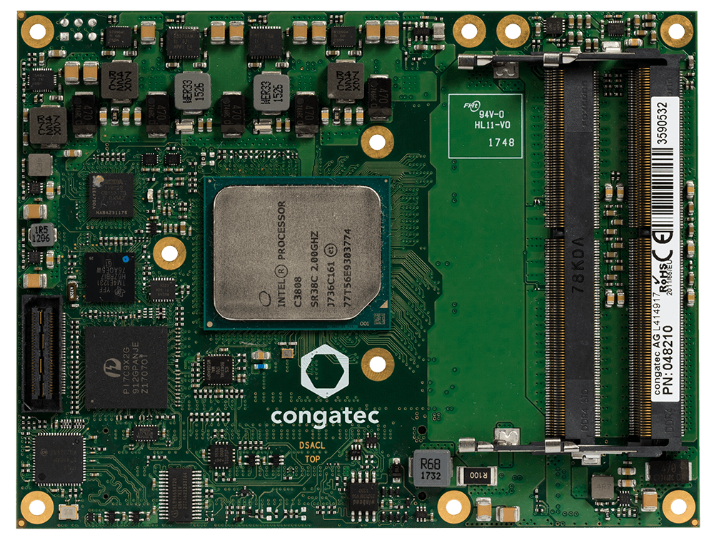
Conga-B7XD
The two modules introduced are:
Conga-B7XD – Intel Xeon D and Pentium D based Conga-B7XD
Congatec has not competed for COM express in the past. But the game is interesting now, as they got themselves prepare for the race. That’s good for inventions. To cope up with the market, they also introduced a Windows supported version of type 7 module, in addition to the Linux. These are specially designed to run in aircraft computers, to make them extra efficient.
Conga-B7XD & Conga-B7AC COMs
Conga-B7XD
Conga-B7XD board is the first one we will take a look and uses a Xeon D 15xx based core. While, Conga-B7AC, the second one is an Atom C3xxx based. It has an inbuilt memory of DDR4 type, ranging up to 96 GB DDR4 SODIMMs which are available via 3x 32GB-ready sockets. The 12 virtual machines on the system now can use 8GB RAM on each partition.
These new set of modules will excel in applications like augmented reality, airborne platforms for connected aircraft, passenger infotainment, Big Data applications, video surveillance, cloud-based flight data recordings, AI-based virtual assistants for improving pilot productivity and efficiency, and similar because of their demand for higher performance and memory, which is something the new Congatec easily cater for.
Due to its use in highly sophisticated devices, like the cockpit and streaming devices, their durability for temperature ranges and vibrations have builtin. Temperature range is matched from 0 to 60°C or an industrial -40 to 85°C, depending on the processor type. While hard sort of vibration and shockproof material is used, all of this together makes it a powerful device to have.
The modules can be integrated with Intel chips ranging from 4x up to 16x core. Xeon system based module supports the 2.1 GHz Xeon D1577 (Conga-B7XD) whereas, Atom provides 2.0 GHz Atom C3958 (Conga-B7AC) processor configuration. The 3x SODIMM sockets are available for both with an ECC or non-EEC DDR4 2400 MT/s RAM ranging up to 48GB for the Conga-B7XD and 96GB for the Conga-B7AC.
Specifications available for the devices:
Dimension: 125 x 90 mm
Shock and vibration resistant.
Temperature range extended.
4x to 16x core configuration available.
2.1 GHz and 2.0 GHz processor configuration available in Xeon and Atom respectively.
DDR4 up to 96 GB system memory.
Dual Sata III storage interface.
Conga-B7XD provides a single Intel I210A GbE controller.
The Conga-B7AC lacks a GbE controller but supports 4x 10GbE with KR.
Conga-B7XD enables 24x PCIe Gen 3 and 8x PCIe 2.0 lanes.
Conga-B7AC gives you 12x and 8x PCIe interfaces
4x USB 2.0 & 4x USB 3.0 (4 available on Conga-B7XD, 2 available on the Conga-B7AC)
Server support included for Linux, Ubuntu, CentOS, Fedora 22, Yocto, Kernel, and windows as well.
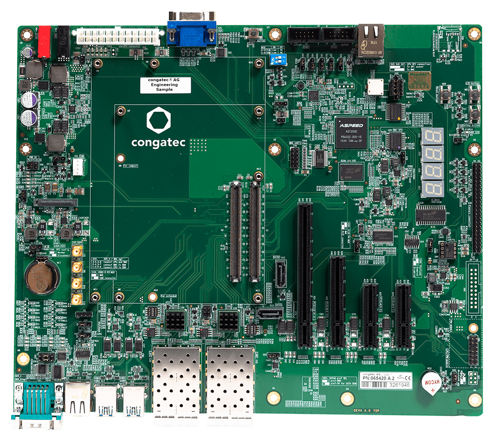
Conga-X7EVAL carrier board
Conga-X7EVAL carrier board
In order to support quick prototyping and developing, Congatec is providing a new Type 7 carrier board called the Conga-X7EVAL that can be used for the Type 7 Modules. It extends out the features of the module with ports like GbE port, PCIe Gen 3 lanes, 4x USB 2.0 & 3.0, and others. The 294 x 244mm carrier board is available in a commercial temperature range model.
Conga-B7XD and Conga-B7AC modules, like any other Congatec module, are available in a variety of configuration options. You can customize it according to your needs and get one. It will align your device with the topmost systems of the technology world. More information may be found on the Conga-B7XD, Conga-B7AC, and Conga-X7EVAL product pages.
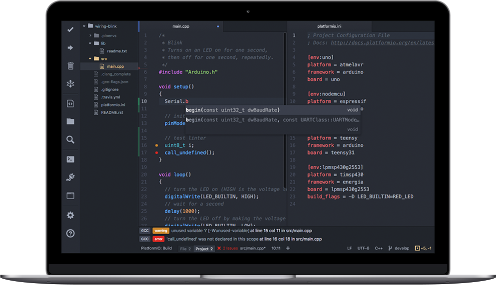
The Arduino IDE is a great programming tool, it is simple to use and it contains probably all resources one will need to build a project, but evaluating it as a code editor, it is a not the perfect tool. It lacks programming aiding features like IntelliSense, code suggestions, auto-complete, auto-correct, and debug tools, which make the development of projects with a large codebase, easy and endears developers to use code editors like Visual Studio Code and Atom. The above reason coupled with the large user base of most of these editors led to the development of plugins/extensions that enabled the use of some of them for development code for Arduino and other compatible boards.
Programming Arduino on Visual Studio Code Editor with Platform.io or Arduino extension – [Link]
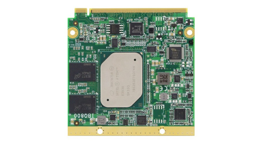
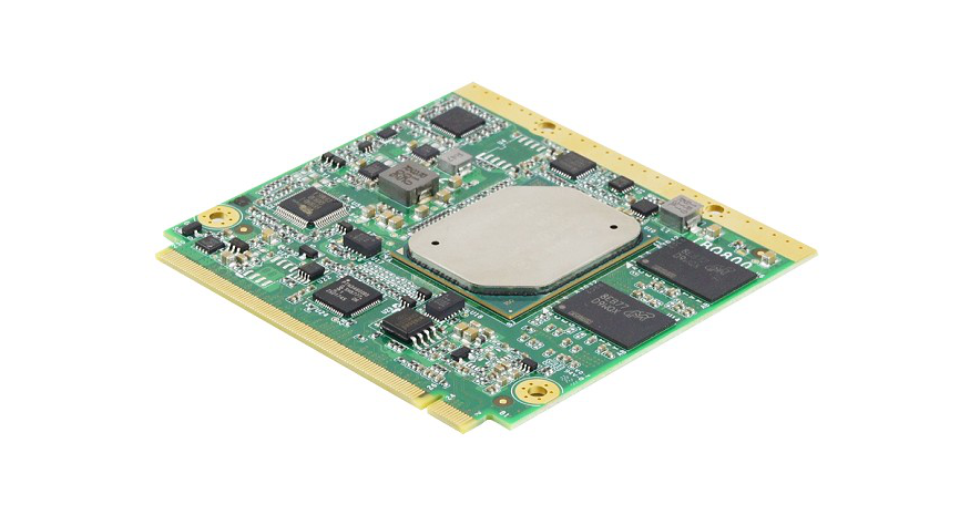
iBASE Technology Inc, a leader in the manufacture of industrial motherboards and embedded systems, is proud to announce the highly integrated IBQ800 low-power CPU module powered by an Intel® Atom™ x7-E3950 @2.0GHz or x5-E3930 @1.8GHz processor. Designed to operate at extended temperatures ranging from -40°C to +85°C, the IBQ800 is suitable for use in industrial environments and vertical market segments including automation, gaming, ATM, transportation, power utility and digital signage.
Built in the Qseven compact module footprint, the IBQ800 offers impressive performance and supports the necessary components and bus interfaces required for the targeted industrial, mobile, and embedded applications. It can be equipped with 8GB or 4GB of LPDDR4 memory and up to 32GB eMMC 5.0 SSD storage on board. The IBQ800 features an Intel® SoC integrated Gen9-LP graphics controller and comes with LVDS or eDP display interface.
In creating the IBQ800, we have kept in mind the needs of embedded system designers for computing performance and rich I/O capabilities in a minimal footprint, as well as long-life availability,” said Wilson Lin, Director of IBASE Product Planning Department. “With dimensions of 70mm by 70mm, it utilizes the established ruggedized MXM connector to interface to the carrier board and route all the I/O signals, including one Gigabit LAN, three USB 3.0, four USB 2.0, HD audio, one COM and two SATA III.
IBQ800 FEATURES
Onboard Intel® Atom™ x5-E3930 @1.8GHz or x7-E3950 @2.0GHz [i-Temp support]
Onboard LPDDR4 memory
1x Intel I210IT PCI-E Gigabit LAN
Supports TPM (2.0), eMMC5.0 (Optional)
Wide-range operating temperature
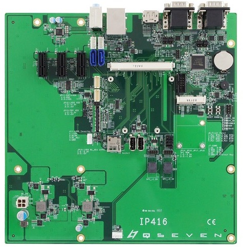
The IBQ800 Qseven CPU module and the IP416 Qseven carrier board are now available. For more information, please contact an IBASE sales representative, or visit www.ibase.com.tw
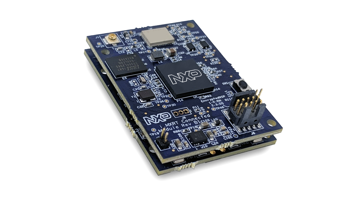
NXP’s MCU-based solution for Amazon’s Alexa Voice Service (AVS) leverages the i.MX RT crossover processor, enabling developers to quickly and easily add Alexa voice assistant capabilities to their products. This ultra-small form-factor, turnkey hardware design comes completely integrated with Amazon qualified software for an out of the box AVS experience.
NXP’s production-ready solution is a time-and-cost-effective way for OEMs to build Alexa into their products. It’s fantastic to see NXP create another solution that simplifies the integration process and enables device makers to bring Alexa built-in products to market even faster. — Priya Abani, AVS Director
In terms of hardware, the i.MX RT 106A Crossover MCU features an Arm Cortex-M7 processor (1Mb of SRAM, 32K I-cache/D-cache, FPU) which supports the microphone (supports 3X MEMS microphones, 2X external digital microphones) and processing , a TFA9894D Class-D Amplifier, 8-/16-bit Parallel Camera Interface, Bluetooth/BLE 4.1, and an (optional) A71CH secure element to handle end-to-end security. The board also sports a secure interface JTAG, PLL OSC, eDMA, 4x Watch Dog, 6x GP Timer, 4x Quadrature ENC, 4x QuadTimer, 4x FlexPWM, and IOMUX.
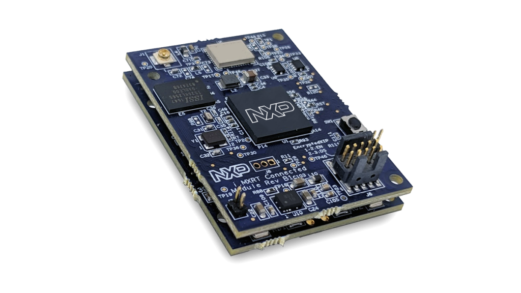
The i.MX RT106A is a solution-specific member of the i.MX RT1060 family of crossover processors, targeting cloud-based embedded voice applications. It features NXP’s advanced implementation of the Arm® Cortex®-M7 core, which operates at speeds up to 600 MHz to provide high CPU performance and best real-time response. i.MX RT106A-based solution enables system designers to easily and inexpensively add voice control capabilities to a wide variety of smart appliances, smart home, smart retail, and smart industry devices.
More information can be found on NXP’s i.MX RT 106A MCU product page.
The Arduino IDE is a great programming tool, it is simple to use and it contains probably all resources one will need to build a project, but evaluating it as a code editor, it is a not the perfect tool. It lacks programming aiding features like IntelliSense, code suggestions, auto-complete, auto-correct, and debug tools, which make the development of projects with a large codebase, easy and endears developers to use code editors like Visual Studio Code and Atom. The above reason coupled with the large user base of most of these editors led to the development of plugins/extensions that enabled the use of some of them for development code for Arduino and other compatible boards.
Programming Arduino with Platform.io or Arduino extension for Visual Studio Code
For this tutorial, we will take a look, how these extensions can be used to program Arduino. Quite a number of editors exist and different variation of extensions have been developed but for today’s tutorial, we will focus on Visual Studio Code (VScode) as our code editor and explore it’s use with the Platform.io and Arduino extensions.
At the end of today’s tutorial, you will know how to develop code for the Arduino and similar/compatible boards using the Arduino and Platform.io extensions on VScode.
Required components
We will use the Arduino blink example for demonstration of today’s tutorial, thus you will only need the target boards.
Arduino Uno (or any other board of the family)
NodeMCU
Any versions/variations of these boards are fine, as long as they work well when you program them using the Arduino IDE. In addition to the components mentioned above, you will need the latest VScode setup. Follow this link to download the setup file and install it on your computer. Ensure you select the “add files to path” option during installation. After installation, restart your computer to allow the installation to settle in.
With this done, we are now ready to use the extensions.
The Arduino Extension
The Arduino IDE for VScode (Visual Studio Code) was one of the earliest extension developed. There is a version of the extension developed by the community while there is another version developed by Microsoft. Any of these extensions can be used. For this tutorial, we will use the Microsoft version of the Arduino extension.
Features and Functionality
The Visual Studio Code Arduino extension retains the ease of use that comes with the Arduino IDE but also provides access to the superb features embedded in the visual studio code which makes coding and debugging a lot easier. Some of the features and functionalities as stated on the extension description, include:
intelliSense and syntax highlighting for Arduino sketches
Verify and upload your sketches in Visual Studio Code
Built-in board and library manager
Built-in example list
Built-in serial monitor
Snippets for sketches
Automatic Arduino project scaffolding
Command Palette (F1) integration of frequently used commands (e.g. Verify, Upload…)
Integrated Arduino Debugging New
Requirements
The only requirement is to have the Arduino IDE installed from arduino.cc. The extension requires the IDE version to be version 1.6.x and up. However, do your best to avoid the version 1.8.7 as it has issues that prevent library and boards installation/updates.
Installation
The Arduino extension can be installed from the extensions market place or via the command line within VScode.
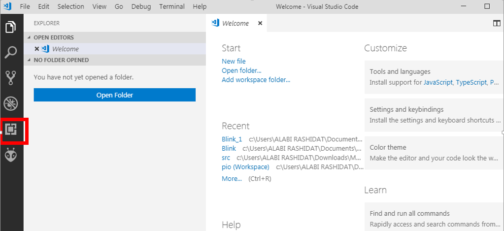
To install from the market place, launch the VScode editor. You should see a welcome page (shown below) -> click on the extension icon (highlighted in the image below) to access the market place.
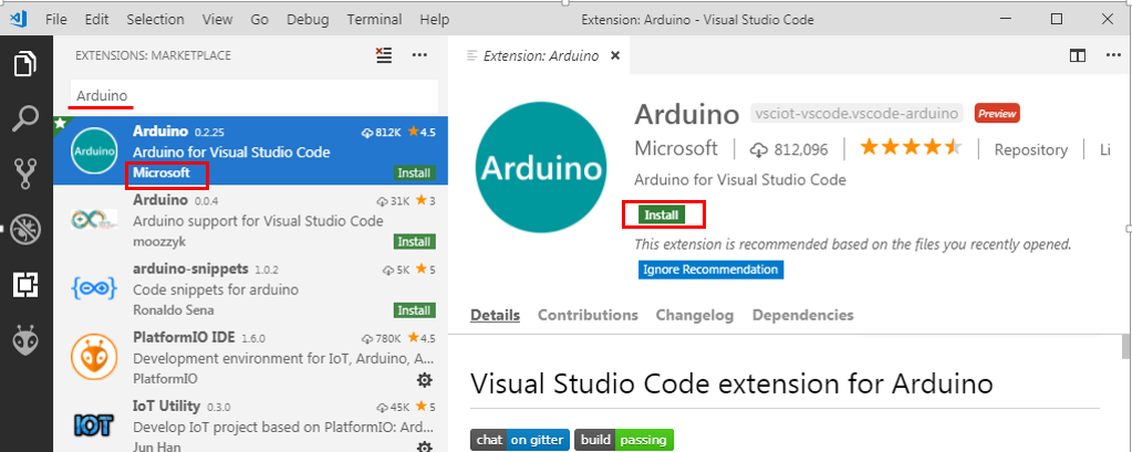
Enter Arduino into the search bar and select the one that says developed by Microsoft. Click on the install button as shown below and re-launch VScode after installation completes.
Installing the Arduino Extension
After re-launch, the Arduino extension should be visible under your enabled extensions. With the installations done, we can now proceed to run an example with Arduino.
Example
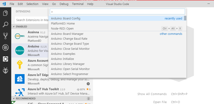
Press the F1 function key to open the command line on VScode. Once the command line becomes visible, type in Arduino. It should show you a list of commands applicable to the Arduino as shown below.
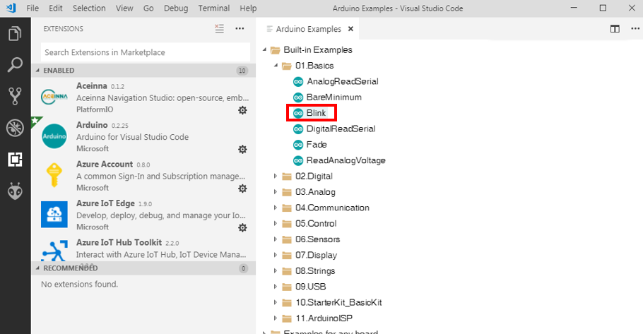
With these commands you can install new Arduino libraries, install new boards, select target board for code upload, select a programmer and pretty much everything you can do with the Arduino IDE or even more. As mentioned earlier, we will use the Arduino blink example as a demonstration. To start with, press F1 and select the “Arduino: Examples” option. Navigate and select the blink example.
Load the Blink Example
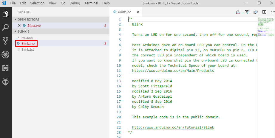
This will open the folder containing the sketch under the explorer pane in a new window. Select the .ino file if you wish to make any changes to the code.
Edit the code
Ready to upload the code?
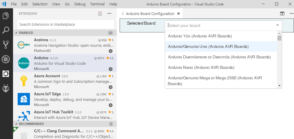
Just like when working with the Arduino IDE, press the F1 function button and select the “Arduino: Board configuration” option to set the target board which in our case, is the Arduino Uno.
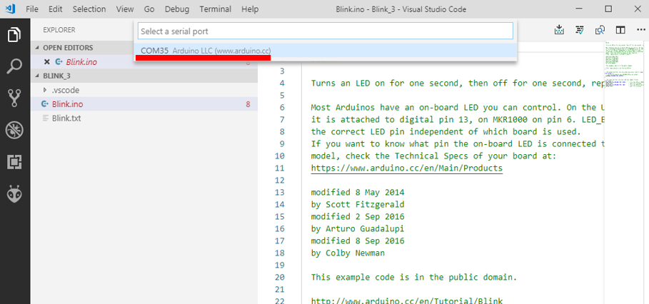
At this point, connect your Arduino board and select the “Arduino:select serial port” option after pressing F1. It will bring up a list of all devices connected to the serial port. Select the one to which your Arduino is connected.
Select COM Port
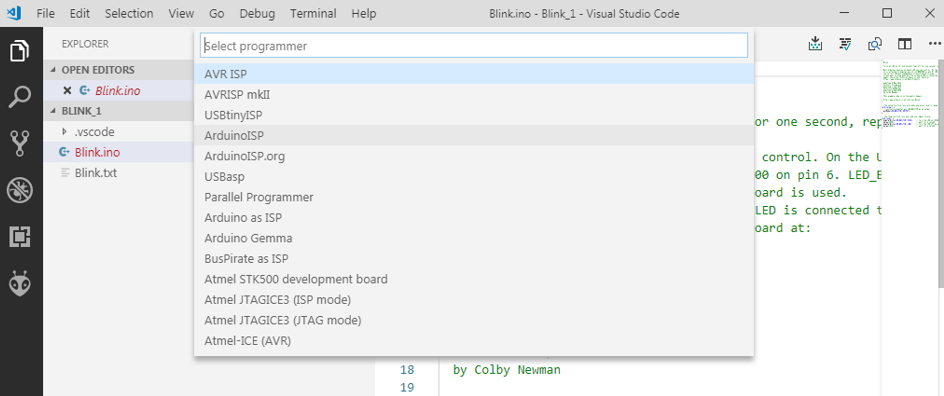
Next, select the programmer by clicking on the “Arduino: Select programmer” option from the function menu. Choose any that you want.
Select Programmer
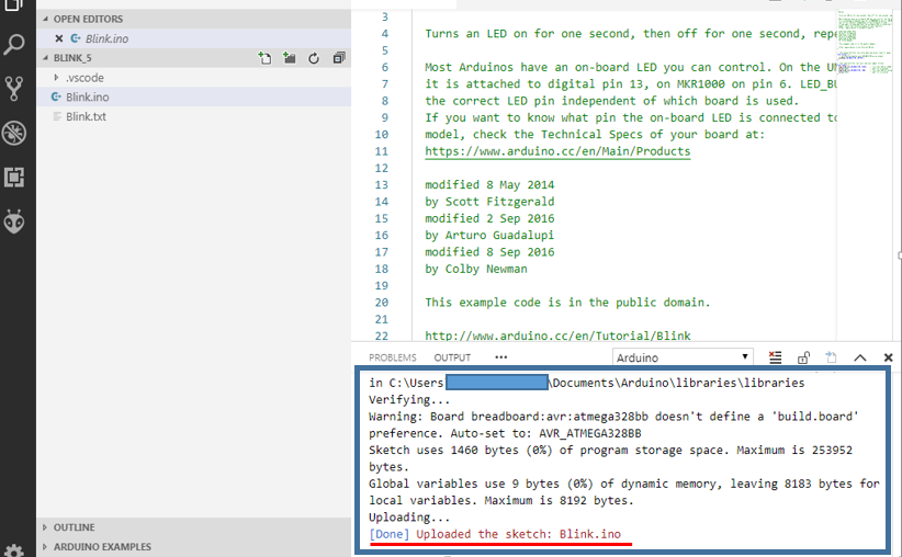
With this done, we are now ready to upload the code. If you made any change to it and you would like to verify code before uploading you can use the “Arduino: Verify” option after pressing F1. If the code is satisfactory and you are ready to upload, press F1 and click the “Arduino: upload function”.
If you follow all the steps carefully, the process should be easy and the code should upload successful as shown below.
Upload Successful
The Platform.io Extension
Platform.io is an open-source platform developed to facilitate the deployment of IoT solutions. It allows the easy integration of IoT specific features like remote firmware update and testing. The platform supports several boards from Arduino, Espressif and their variations to TI’s MSP430, Tiva and others. It also supports frameworks like the Arduino, Energia for TI boards, and Mbed, effectively making it one of the most comprehensive cross-platform development tool for IoT.
Platform.io Features
Some of the outstanding features of platform.io according to their website include:
Cross-platform build system without external dependencies to the OS software: 550+ embedded boards, 30+ development platforms, 15+ frameworks
Just like we did with the Arduino extension for VScode, we will take a look on how the platformio.org extension for VScode can be used for programming Arduino boards.
Installation
Just like the Arduino extension, the platform.io extension for visual studio code can also be installed via extension market place.
Click on the extensions/package manager icon, when it opens, enter “platformIO IDE” into the search bar and click on the install button as shown below. After installation, reload VScode to allow installation to take effect.
Putting it to Use
Once the reload is complete, a platform.io icon will be visible on the sidebar and the platform.io toolbar will be added to the status bar of VScode. The toolbar contains buttons for popular commands. This makes it easy to quick build, upload, or perform any of the commands without much navigation.
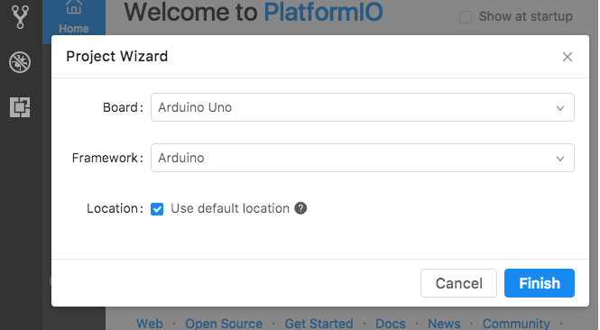
As mentioned earlier, we will use the blink example here too. To create a new project, click on the platform.io home icon and select the “New Project” button. A window similar to the one shown below should open up.
Select Platform and Board type
This window will allow you to select the board, the framework and other things to set up the IDE for use with your target board. Since we will use the Arduino Uno, we select it as the board type and the Arduino IDE as the platform. If this were to be the NodeMCU, you will need to select the nodemcu as the board type and the Arduino or the ESPressif 8266 as the framework.
With the setup done, a new project folder is created. Open the main.cpp file under the src folder to write the code for your project.
Since we are using the blink example, you can copy and paste the code below into the code editor.
/**
 * Blink
 *
 * Turns on an LED on for one second,
 * then off for one second, repeatedly.
 */
#include "Arduino.h"

// Set LED_BUILTIN if it is not defined by Arduino framework
// #define LED_BUILTIN 13

void setup()
{
  // initialize LED digital pin as an output.
  pinMode(LED_BUILTIN, OUTPUT);
}

void loop()
{
  // turn the LED on (HIGH is the voltage level)
  digitalWrite(LED_BUILTIN, HIGH);

  // wait for a second
  delay(1000);

  // turn the LED off by making the voltage LOW
  digitalWrite(LED_BUILTIN, LOW);

   // wait for a second
  delay(1000);
}
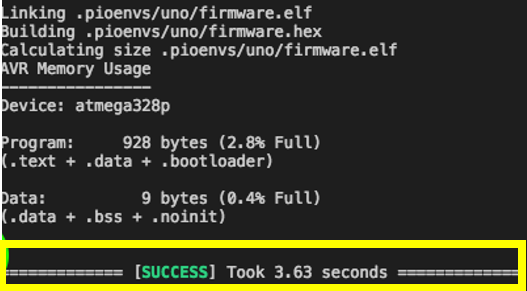
With this done, use the “Build button” on the toolbar to build your code and the “Upload button” to upload it to the target Arduino board. If the installation was properly done, you should get the success remarks on the console window.
Conclusion
The two extensions we examined today are quite powerful. They can be used to develop code for all kind of boards that are compatible with the Arduino IDE and boards that are not Arduino compatible but are supported by the plaform.io IDE (when using their extension). These extensions provide a lot of flexibility and features that make the development of projects with a large code base easy, ensuring you don’t repeat lines via code suggestions and intellisense. They also ensure you keep all the files for a project in a single folder which makes it easy to manipulate and move things around. It might be handy for your next mega project.
Feel free to reach out via the comment section if you have any difficulty setting things up.