DIY Altimeter using a NEO UBLOX GPS module, a Color OLED and Arduino

GPS technology plays an important role in our everyday life. From easy human navigation to navigation of aircraft, it helps solving different location-related problems. However, aside from providing location details, the NMEA data obtained from satellites by GPS modules also carry information for other parameters like altitude, pressure, date and time etc. The implication of this is that GPS modules can be used also in projects where these other parameters are needed.

For today’s tutorial, we will use the UBLOX NEO-6M GPS module to determine the altitude of our place. A good application for this project would be a drone setup where the altitude is required as feedback to the IMU or other similar scenarios. While diverse kind of Arduino compatible GPS modules exists, they are often bulky and come with other constraints like high power requirements which put limitations on the project in which they can be used. This is where the UBLOX NEO 6M GPS Module comes in.

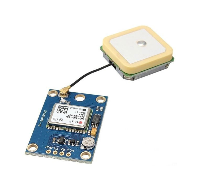
The module is compact and about the same size of small Arduino boards and this enable them to be easily fitted into any small Arduino project. The NEO-6M GPS module is a high-performing GPS receiver with a built-in 25 x 25 x 4mm ceramic antenna, which equips the module with a strong satellite search capability. The module communicates with connected microcontroller via serial protocol and operates on a voltage level between 3-5V.

We will use the GPS module to obtain altitude data and display them on an OLED display. At the end of the tutorial, you would know how to obtain diverse kind of information from a GPS module using NMEA protocol.

Required components

The following components are required to build this project;

  1. GPS Module
  2. Color OLED
  3. Arduino Uno
  4. Small Breadboard
  5. Wires
  6. Xiaomi Power Bank
Required components

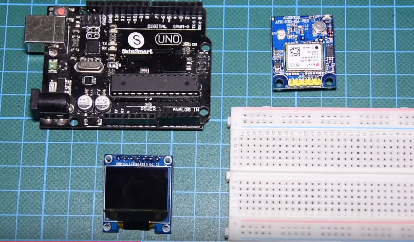
As usual, all the components listed above can be bought via the links attached to them. It is also important to note that, the power bank is only needed for those who may want to test the project, in standalone mode.

Schematics

The schematic for this project is fairly simple. Asides the Arduino, we have two other major components, the GPS Module and the OLED display. The GPS module communicates over serial so it will be connected to serial pins of the Arduino. However, we will use software serial-based communication to avoid interference on the hardware serial line, since it is what the Arduino uses to communicate with the PC.

Connect the components as shown in the schematics below.

Schematics

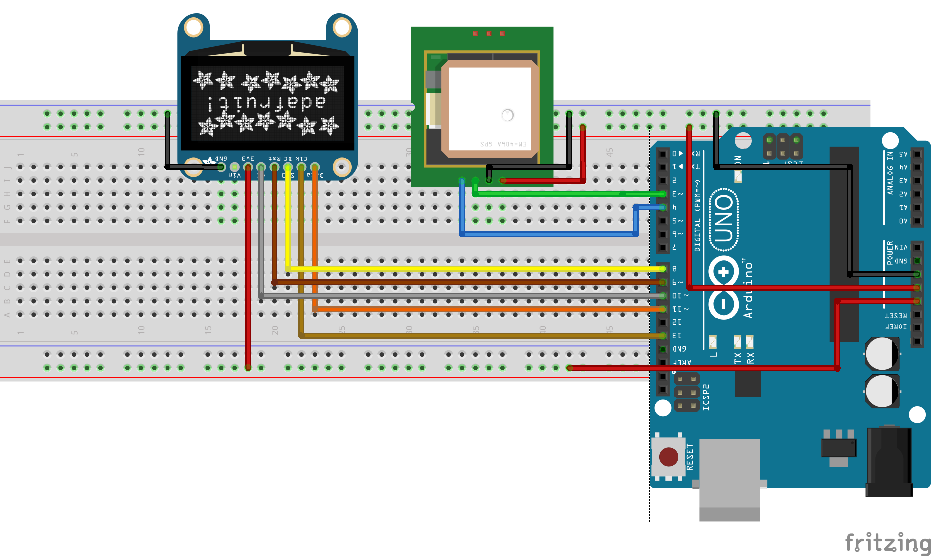
To make the connections easier to follow, a pin map showing how each of the components connects to the Arduino is shown below.

Arduino – OLED Display

GND – GND
3.3V – VCC
D13 – SCL
D11 – SDA
D9 – RES
D8 – DC
D10 – CS

Arduino – GPS

GND – GND
5v – VCC
D3 – RX
D4 – TX

Go over the connections once again to be sure everything is as it should be.

Code

As mentioned earlier, we will use the GPS module not to obtain location information, like longitude and latitude, but to show how other parameters like altitude can be derived from the GPS output.

GPS modules as soon as they connect to satellites they pull a bunch of information which are referred to as NMEA data. This data contains useful information like location, altitude, pressure etc. Typical NMEA data are shown in the image below.

NMEA Data

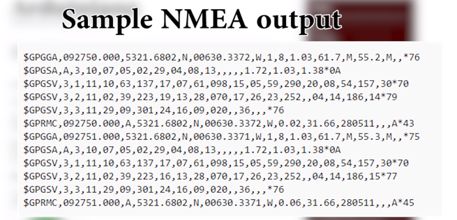
Making sense of this information and extracting the needed data can be quite a task. To make things easy for us, we will use the tinyGPS++ library which already has all the functions required to extract specific information from the NMEA data. The Library can be downloaded via the link attached.  In addition to tinyGPS++ library, we will use the Adafruit GFX library. The GFX library will make it easy to interact with the OLED display.

To do a quick breakdown of the code, as usual, we will start by including the libraries required for the project after which we define the pins of the Arduino to which the OLED is connected.

// writtern by Nick Koumaris
//Info@educ8s.tv

#include <SoftwareSerial.h> 
#include <Adafruit_GFX.h>
#include <Adafruit_SSD1331.h>
#include <SPI.h>
#include "TinyGPS++.h"

#define sclk 13
#define mosi 11
#define cs   10
#define rst  9
#define dc

Next we specify the variables to represent the hex  number of the colors to be used by the project and also create an instance of the tinyGPS++ library. This instance will be used to refer to the module which pass through the code.

#define  BLACK           0x0000
#define BLUE            0x001F
#define RED             0xF800
#define GREEN           0x07E0
#define CYAN            0x07FF
#define MAGENTA         0xF81F
#define YELLOW          0xFFE0  
#define WHITE           0xFFFF

TinyGPSPlus gps;

To make the data display more user friendly, a splach screen and icons were created so the information can be displayed in a neat and cool way. The char code representing the UI and the icons are declared below. To learn how to generate your own code to encode an image, you can check past tutorials.

static const unsigned char PROGMEM title[] = {

0x0,0x0,0x0,0x0,0x0,0x0,0x0,0x0,0x0,0x0,0x0,0x0,
0x0,0x3f,0xc0,0xff,0xc0,0xf,0xe0,0x0,0x0,0x0,0x0,0x0,
0x0,0xff,0xe0,0xff,0xf0,0x3f,0xf0,0x0,0x0,0x0,0x0,0x0,
0x3,0xff,0xe0,0xff,0xf8,0x7f,0xf0,0x0,0x0,0x0,0x0,0x0,
0x7,0xff,0xe0,0xf0,0xfc,0xff,0xf0,0x0,0x0,0x0,0x0,0x0,
0x7,0xe0,0x20,0xf0,0x3c,0xf8,0x10,0x0,0x0,0x0,0x0,0x0,
0xf,0x80,0x0,0xf0,0x3c,0xf0,0x0,0x0,0x0,0x0,0x0,0x0,
0xf,0x0,0x0,0xf0,0x3c,0xf0,0x0,0x0,0x0,0x0,0x0,0x0,
0x1e,0x0,0x0,0xf0,0x3c,0xfc,0x0,0x0,0x0,0x0,0x0,0x0,
0x1e,0xf,0xf0,0xf0,0x3c,0x7f,0x0,0x0,0x0,0x0,0x0,0x0,
0x1e,0xf,0xf0,0xf0,0xf8,0x3f,0xc0,0x0,0x0,0x0,0x0,0x0,
0x1e,0xf,0xf0,0xff,0xf8,0x1f,0xe0,0x0,0x0,0x0,0x0,0x0,
0x1e,0xf,0xf0,0xff,0xe0,0x7,0xf0,0x0,0x0,0x0,0x0,0x0,
0x1e,0x0,0xf0,0xff,0x80,0x1,0xf8,0x0,0x0,0x0,0x0,0x0,
0x1f,0x0,0xf0,0xf0,0x0,0x0,0x78,0x0,0x0,0x0,0x0,0x0,
0xf,0x80,0xf0,0xf0,0x0,0x80,0x78,0x0,0x0,0x0,0x0,0x0,
0xf,0xc0,0xf0,0xf0,0x0,0xe0,0xf8,0x0,0x0,0x0,0x0,0x0,
0x7,0xff,0xf0,0xf0,0x0,0xff,0xf8,0x0,0x0,0x0,0x0,0x0,
0x3,0xff,0xf0,0xf0,0x0,0xff,0xf0,0x0,0x0,0x0,0x0,0x0,
0x1,0xff,0xf0,0xf0,0x0,0xff,0xe0,0x0,0x0,0x0,0x0,0x0,
0x0,0x7f,0x80,0xf0,0x0,0x3f,0x80,0x0,0x0,0x0,0x0,0x0,
0x0,0x0,0x0,0x0,0x0,0x0,0x0,0x0,0x0,0x0,0x0,0x0,
0x0,0xe0,0x71,0xff,0xf9,0xe0,0xf1,0xfd,0xff,0x7f,0x3f,0x80,
0x0,0xf0,0x71,0xff,0xf9,0xf0,0xf1,0xfd,0xff,0x7f,0x3f,0xc0,
0x1,0xb0,0x70,0x38,0x71,0xb0,0xb1,0xc0,0x38,0x70,0x38,0xc0,
0x1,0xb0,0x70,0x38,0x71,0xf1,0xb1,0xc0,0x38,0x70,0x38,0xc0,
0x3,0xb8,0x70,0x38,0x71,0xf9,0xb1,0xf8,0x38,0x7e,0x39,0xc0,
0x3,0x18,0x70,0x38,0x71,0xdb,0xb1,0xf8,0x38,0x7e,0x3f,0x80,
0x3,0x1c,0x70,0x38,0x71,0xdb,0x31,0xc0,0x38,0x70,0x3f,0x80,
0x7,0xfc,0x70,0x38,0x71,0xdf,0x31,0xc0,0x38,0x70,0x39,0x80,
0x7,0xfc,0x70,0x38,0x71,0xce,0x31,0xc0,0x38,0x70,0x39,0xc0,
0x6,0xe,0x7f,0x38,0xf9,0xce,0x31,0xfc,0x38,0x7f,0x38,0xe0,
0xe,0xe,0x7f,0x38,0xf9,0xce,0x31,0xfc,0x38,0x7f,0x38,0xf0,
0x0,0x0,0x0,0x0,0x0,0x0,0x0,0x0,0x0,0x0,0x0,0x0,
0x0,0x0,0x0,0x0,0x0,0x0,0x0,0x0,0x0,0x0,0x0,0x0
};
static const unsigned char PROGMEM ui[] =
{
0xff,0xff,0xff,0xff,0xff,0xff,0xff,0xff,0xff,0xff,0xff,0xff,
0x80,0x0,0x0,0x0,0x0,0x0,0x0,0x0,0x0,0x0,0x0,0x1,
0x80,0xe0,0x38,0x7f,0xf7,0xdf,0xfc,0xe0,0xe1,0xfe,0x7,0xf1,
0x81,0xf0,0x38,0x7f,0xf7,0xdf,0xfc,0xe0,0xe1,0xff,0x7,0xf1,
0x81,0xb0,0x38,0x7,0x3,0x81,0xc0,0xe0,0xe1,0xc7,0x87,0x1,
0x81,0xb8,0x38,0x7,0x3,0x81,0xc0,0xe0,0xe1,0xc3,0xc7,0x1,
0x83,0xb8,0x38,0x7,0x3,0x81,0xc0,0xe0,0xe1,0xc1,0xc7,0x1,
0x83,0xb8,0x38,0x7,0x3,0x81,0xc0,0xe0,0xe1,0xc1,0xc7,0xe1,
0x87,0x1c,0x38,0x7,0x3,0x81,0xc0,0xe0,0xe1,0xc1,0xc7,0xe1,
0x87,0x1c,0x38,0x7,0x3,0x81,0xc0,0xe0,0xe1,0xc1,0xc7,0x1,
0x87,0xfc,0x38,0x7,0x3,0x81,0xc0,0xe0,0xe1,0xc1,0xc7,0x1,
0x8f,0xfe,0x38,0x7,0x3,0x81,0xc0,0xe0,0xe1,0xc3,0x87,0x1,
0x8e,0xe,0x38,0x7,0x3,0x81,0xc0,0x71,0xc1,0xc7,0x87,0x1,
0x8e,0xe,0x3f,0x87,0x7,0xc1,0xc0,0x7f,0xc1,0xff,0x7,0xf1,
0x9c,0x7,0x3f,0x87,0x7,0xc1,0xc0,0x1f,0x1,0xfc,0x7,0xf1,
0x80,0x0,0x0,0x0,0x0,0x0,0x0,0x0,0x0,0x0,0x0,0x1,
0xff,0xff,0xff,0xff,0xff,0xff,0xff,0xff,0xff,0xff,0xff,0xff,
0x80,0x0,0x0,0x0,0x0,0x0,0x0,0x0,0x0,0x0,0x0,0x1,
0xff,0xff,0xff,0xff,0xff,0xff,0xff,0xff,0xff,0xff,0xff,0xff
};

static const unsigned char PROGMEM gpsIcon[] = {

0x0,0xe0,0x0,0x0,
0x1,0xf0,0x0,0x0,
0x3,0xf8,0x0,0x0,
0x3,0x98,0x0,0x0,
0xe,0x7,0x0,0x0,
0xe,0x7,0x80,0x0,
0xe,0x3,0x80,0x0,
0x3,0x81,0xfc,0x0,
0x3,0xc1,0xfc,0x0,
0x1,0xc1,0xfe,0x0,
0x0,0xf7,0xfe,0x0,
0x0,0x3f,0xfc,0x0,
0x0,0x3f,0xfc,0x0,
0x0,0x1f,0xff,0x80,
0x0,0x1f,0xfb,0x80,
0xcc,0x1f,0xe1,0xc0,
0xce,0x1f,0xe0,0x70,
0xce,0xf,0xe0,0x70,
0x6e,0x7,0x60,0x38,
0x67,0x0,0x78,0xc,
0x63,0x0,0x1c,0x1c,
0x73,0x80,0x1c,0x3c,
0x71,0xf0,0x7,0x70,
0x30,0xf8,0x7,0xf0,
0x1c,0x3e,0x3,0xc0,
0xf,0x0,0x0,0x80,
0xf,0x80,0x0,0x0,
0x3,0xf0,0x0,0x0,
0x0,0xfe,0x0,0x0,
0x0,0xe,0x0,0x0
};

Next, we initialize the software serial library stating with the pins of the arduino to be used as the software TX and RX pins. We also create an instance of the OLED Library and move from there to the void setup() function.

SoftwareSerial SoftSerial(4, 3); //RX, TX
Adafruit_SSD1331 display = Adafruit_SSD1331(cs, dc, rst);

Under the void setup() function, we initialize the display and serial communications declaring the baud rate at which we want the devices to communicate. The preset baud rate for the particular GPS module used for this project is 9600bps. Ensure it is the same for your module or modify accordingly. To round things off, we display the UI, getting the OLED ready to display altitude data. Next is the void loop() function.

void setup() 
{ 
  
  display.begin();
  display.fillScreen(BLACK);

  printSplashScreen();
  
  SoftSerial.begin(9600);  // the SoftSerial baud rate 
  delay(1000);
  Serial.begin(9600);      // the Serial port of Arduino baud rate. 
  delay(2000);
  printUI();

}

Under the void loop function, we check if data is being received by the GPS module and we use the gps.altitude.meters() function to extract altitude information from the module. The code also shows examples of how location information, can be obtained from the NMEA data, using the gps.location.lat() and the gps.location.lng() functions to get longitude and latitude information.

void loop() 
{ 
  String altitude ;
  
  while (SoftSerial.available() > 0)
   gps.encode(SoftSerial.read());
  
  if (gps.location.isUpdated())
  {
    Serial.print("LAT="); Serial.print(gps.location.lat(), 6);
    Serial.print("  LNG="); Serial.println(gps.location.lng(), 6);
  }

  if (gps.altitude.isUpdated())
  {
    Serial.print("Altitude:");
    Serial.println(gps.altitude.meters());
    altitude = String((int)gps.altitude.meters())+" m";
    display.setCursor(18,35);
    display.print(altitude);
  }
}

The complete code for this project is attached below and under the download section of this tutorial.

//Written by Nick Koumaris
//info@educ8s.tv

#include <SoftwareSerial.h> 
#include <Adafruit_GFX.h>
#include <Adafruit_SSD1331.h>
#include <SPI.h>
#include "TinyGPS++.h"

#define sclk 13
#define mosi 11
#define cs   10
#define rst  9
#define dc   8

// Color definitions
#define  BLACK           0x0000
#define BLUE            0x001F
#define RED             0xF800
#define GREEN           0x07E0
#define CYAN            0x07FF
#define MAGENTA         0xF81F
#define YELLOW          0xFFE0  
#define WHITE           0xFFFF

TinyGPSPlus gps;
static const unsigned char PROGMEM title[] = {

0x0,0x0,0x0,0x0,0x0,0x0,0x0,0x0,0x0,0x0,0x0,0x0,
0x0,0x3f,0xc0,0xff,0xc0,0xf,0xe0,0x0,0x0,0x0,0x0,0x0,
0x0,0xff,0xe0,0xff,0xf0,0x3f,0xf0,0x0,0x0,0x0,0x0,0x0,
0x3,0xff,0xe0,0xff,0xf8,0x7f,0xf0,0x0,0x0,0x0,0x0,0x0,
0x7,0xff,0xe0,0xf0,0xfc,0xff,0xf0,0x0,0x0,0x0,0x0,0x0,
0x7,0xe0,0x20,0xf0,0x3c,0xf8,0x10,0x0,0x0,0x0,0x0,0x0,
0xf,0x80,0x0,0xf0,0x3c,0xf0,0x0,0x0,0x0,0x0,0x0,0x0,
0xf,0x0,0x0,0xf0,0x3c,0xf0,0x0,0x0,0x0,0x0,0x0,0x0,
0x1e,0x0,0x0,0xf0,0x3c,0xfc,0x0,0x0,0x0,0x0,0x0,0x0,
0x1e,0xf,0xf0,0xf0,0x3c,0x7f,0x0,0x0,0x0,0x0,0x0,0x0,
0x1e,0xf,0xf0,0xf0,0xf8,0x3f,0xc0,0x0,0x0,0x0,0x0,0x0,
0x1e,0xf,0xf0,0xff,0xf8,0x1f,0xe0,0x0,0x0,0x0,0x0,0x0,
0x1e,0xf,0xf0,0xff,0xe0,0x7,0xf0,0x0,0x0,0x0,0x0,0x0,
0x1e,0x0,0xf0,0xff,0x80,0x1,0xf8,0x0,0x0,0x0,0x0,0x0,
0x1f,0x0,0xf0,0xf0,0x0,0x0,0x78,0x0,0x0,0x0,0x0,0x0,
0xf,0x80,0xf0,0xf0,0x0,0x80,0x78,0x0,0x0,0x0,0x0,0x0,
0xf,0xc0,0xf0,0xf0,0x0,0xe0,0xf8,0x0,0x0,0x0,0x0,0x0,
0x7,0xff,0xf0,0xf0,0x0,0xff,0xf8,0x0,0x0,0x0,0x0,0x0,
0x3,0xff,0xf0,0xf0,0x0,0xff,0xf0,0x0,0x0,0x0,0x0,0x0,
0x1,0xff,0xf0,0xf0,0x0,0xff,0xe0,0x0,0x0,0x0,0x0,0x0,
0x0,0x7f,0x80,0xf0,0x0,0x3f,0x80,0x0,0x0,0x0,0x0,0x0,
0x0,0x0,0x0,0x0,0x0,0x0,0x0,0x0,0x0,0x0,0x0,0x0,
0x0,0xe0,0x71,0xff,0xf9,0xe0,0xf1,0xfd,0xff,0x7f,0x3f,0x80,
0x0,0xf0,0x71,0xff,0xf9,0xf0,0xf1,0xfd,0xff,0x7f,0x3f,0xc0,
0x1,0xb0,0x70,0x38,0x71,0xb0,0xb1,0xc0,0x38,0x70,0x38,0xc0,
0x1,0xb0,0x70,0x38,0x71,0xf1,0xb1,0xc0,0x38,0x70,0x38,0xc0,
0x3,0xb8,0x70,0x38,0x71,0xf9,0xb1,0xf8,0x38,0x7e,0x39,0xc0,
0x3,0x18,0x70,0x38,0x71,0xdb,0xb1,0xf8,0x38,0x7e,0x3f,0x80,
0x3,0x1c,0x70,0x38,0x71,0xdb,0x31,0xc0,0x38,0x70,0x3f,0x80,
0x7,0xfc,0x70,0x38,0x71,0xdf,0x31,0xc0,0x38,0x70,0x39,0x80,
0x7,0xfc,0x70,0x38,0x71,0xce,0x31,0xc0,0x38,0x70,0x39,0xc0,
0x6,0xe,0x7f,0x38,0xf9,0xce,0x31,0xfc,0x38,0x7f,0x38,0xe0,
0xe,0xe,0x7f,0x38,0xf9,0xce,0x31,0xfc,0x38,0x7f,0x38,0xf0,
0x0,0x0,0x0,0x0,0x0,0x0,0x0,0x0,0x0,0x0,0x0,0x0,
0x0,0x0,0x0,0x0,0x0,0x0,0x0,0x0,0x0,0x0,0x0,0x0
};
static const unsigned char PROGMEM ui[] =
{
0xff,0xff,0xff,0xff,0xff,0xff,0xff,0xff,0xff,0xff,0xff,0xff,
0x80,0x0,0x0,0x0,0x0,0x0,0x0,0x0,0x0,0x0,0x0,0x1,
0x80,0xe0,0x38,0x7f,0xf7,0xdf,0xfc,0xe0,0xe1,0xfe,0x7,0xf1,
0x81,0xf0,0x38,0x7f,0xf7,0xdf,0xfc,0xe0,0xe1,0xff,0x7,0xf1,
0x81,0xb0,0x38,0x7,0x3,0x81,0xc0,0xe0,0xe1,0xc7,0x87,0x1,
0x81,0xb8,0x38,0x7,0x3,0x81,0xc0,0xe0,0xe1,0xc3,0xc7,0x1,
0x83,0xb8,0x38,0x7,0x3,0x81,0xc0,0xe0,0xe1,0xc1,0xc7,0x1,
0x83,0xb8,0x38,0x7,0x3,0x81,0xc0,0xe0,0xe1,0xc1,0xc7,0xe1,
0x87,0x1c,0x38,0x7,0x3,0x81,0xc0,0xe0,0xe1,0xc1,0xc7,0xe1,
0x87,0x1c,0x38,0x7,0x3,0x81,0xc0,0xe0,0xe1,0xc1,0xc7,0x1,
0x87,0xfc,0x38,0x7,0x3,0x81,0xc0,0xe0,0xe1,0xc1,0xc7,0x1,
0x8f,0xfe,0x38,0x7,0x3,0x81,0xc0,0xe0,0xe1,0xc3,0x87,0x1,
0x8e,0xe,0x38,0x7,0x3,0x81,0xc0,0x71,0xc1,0xc7,0x87,0x1,
0x8e,0xe,0x3f,0x87,0x7,0xc1,0xc0,0x7f,0xc1,0xff,0x7,0xf1,
0x9c,0x7,0x3f,0x87,0x7,0xc1,0xc0,0x1f,0x1,0xfc,0x7,0xf1,
0x80,0x0,0x0,0x0,0x0,0x0,0x0,0x0,0x0,0x0,0x0,0x1,
0xff,0xff,0xff,0xff,0xff,0xff,0xff,0xff,0xff,0xff,0xff,0xff,
0x80,0x0,0x0,0x0,0x0,0x0,0x0,0x0,0x0,0x0,0x0,0x1,
0xff,0xff,0xff,0xff,0xff,0xff,0xff,0xff,0xff,0xff,0xff,0xff
};

static const unsigned char PROGMEM gpsIcon[] = {

0x0,0xe0,0x0,0x0,
0x1,0xf0,0x0,0x0,
0x3,0xf8,0x0,0x0,
0x3,0x98,0x0,0x0,
0xe,0x7,0x0,0x0,
0xe,0x7,0x80,0x0,
0xe,0x3,0x80,0x0,
0x3,0x81,0xfc,0x0,
0x3,0xc1,0xfc,0x0,
0x1,0xc1,0xfe,0x0,
0x0,0xf7,0xfe,0x0,
0x0,0x3f,0xfc,0x0,
0x0,0x3f,0xfc,0x0,
0x0,0x1f,0xff,0x80,
0x0,0x1f,0xfb,0x80,
0xcc,0x1f,0xe1,0xc0,
0xce,0x1f,0xe0,0x70,
0xce,0xf,0xe0,0x70,
0x6e,0x7,0x60,0x38,
0x67,0x0,0x78,0xc,
0x63,0x0,0x1c,0x1c,
0x73,0x80,0x1c,0x3c,
0x71,0xf0,0x7,0x70,
0x30,0xf8,0x7,0xf0,
0x1c,0x3e,0x3,0xc0,
0xf,0x0,0x0,0x80,
0xf,0x80,0x0,0x0,
0x3,0xf0,0x0,0x0,
0x0,0xfe,0x0,0x0,
0x0,0xe,0x0,0x0
};

SoftwareSerial SoftSerial(4, 3); //RX, TX
Adafruit_SSD1331 display = Adafruit_SSD1331(cs, dc, rst);

void setup() 
{ 
  
  display.begin();
  display.fillScreen(BLACK);

  printSplashScreen();
  
  SoftSerial.begin(9600);  // the SoftSerial baud rate 
  delay(1000);
  Serial.begin(9600);      // the Serial port of Arduino baud rate. 
  delay(2000);
  printUI();

} 

void loop() 
{ 
  String altitude ;
  
  while (SoftSerial.available() > 0)
   gps.encode(SoftSerial.read());
  
  if (gps.location.isUpdated())
  {
    Serial.print("LAT="); Serial.print(gps.location.lat(), 6);
    Serial.print("  LNG="); Serial.println(gps.location.lng(), 6);
  }

  if (gps.altitude.isUpdated())
  {
    Serial.print("Altitude:");
    Serial.println(gps.altitude.meters());
    altitude = String((int)gps.altitude.meters())+" m";
    display.setCursor(18,35);
    display.print(altitude);
  }
}

void printSplashScreen()
{
    
  display.drawBitmap(0,0,title,96,64,RED);
  display.drawBitmap(65,0,gpsIcon,30,30,GREEN);
}

void printUI()
{
  display.fillScreen(BLACK);
  display.setTextColor(WHITE);
  display.drawBitmap(0,0,ui,96,64,WHITE);
  display.setTextSize(2);
  display.setTextColor(BLUE,BLACK);
}

Demo

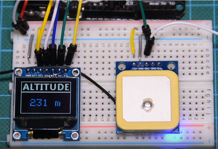
The demo for this project is quite simple. Go over the schematics to confirm you have everything hooked-up correctly then upload the code to your Arduino board.  After a few minutes you should see the altitude of the device’s current location being displayed on the OLED. Be sure to test the module outdoors and with a view to the sky.

Demo

That’s it for this tutorial guys. Thanks for going through it to the end. If you have questions around today’s tutorial, feel free to reach out to me via the comment section.

Till Next time!

The video version of this tutorial is available on youtube.


Osram’s SFH 5701 Ambient Light Sensor (ALS)

Osram Opto Semiconductors presents the SFH 5701 A01, a new ambient light sensor (ALS) with integrated circuitry (IC).

The SFH 5701 A01 ambient light sensor is Osram Opto Semiconductors’ latest addition to its portfolio for the automotive sector and the company’s first IC-based component for which a separate power supply pin is not required. The ambient light sensor (ALS) is an active component in which the IC is powered by the signal current and is therefore not reliant on an external power supply. It therefore has only two pins instead of three or more, making it much easier to connect and operate. The special filter encapsulation of the SFH 5701 A01 lets mainly green light through and filters out infrared wavelengths very efficiently. This ensures that the surface-mountable component is ideally adapted to the spectral sensitivity of the human eye, which also is most sensitive to light in the green range of the color spectrum. Overall, the sensor detects light in the spectrum between 450 nm and 700 nm – the visible range for the human eye.

SFH 5701 A01 is an analog component with a linear integrated amplifier which supplies a typical signal of 135 µA at 100 lux. The high dynamic range and high sensitivity at low illuminance of 0.01 lux combine to produce reliable light measurements for a wide range of ambient light conditions. The ALS delivers precise measurements even behind dark glass or plastic covers – a major benefit for passenger cell designs. Its footprint of 1.25 mm x 2.0 mm x 0.8 mm also means it is extremely compact. Integrated thermal compensation makes the component insensitive to fluctuations in temperature.

The dark green encapsulation of the package of our SFH 5701 A01 offers many benefits, not least in terms of design. The component is unobtrusive in the car, particularly if installed behind a semi-transparent cover. Together with its small size and high sensitivity, this makes the component a particularly versatile and efficient solution for many different in-car applications

,said Walter Rothmund, Marketing Manager Automotive for the Emitter Laser Sensor section at Osram Opto Semiconductors.

Block Diagram

  • The analog ALS IC has an analog current output proportional to the incident light level.
  • Rload converts the current output to a voltage output (VOUT): to interface to an ADC
  • This voltage output is typically applied to either the input of an ADC interface on an MCU or directly as an input to an LED driver IC equipped with auto-luminous control
  • RC low-pass filter to remove low-frequency flickering noise with a cut-off frequency (fc) of 50 Hz where fc = 1/(2*π*R*C)

Features

  • Simple implementation with just two pins
  • Built-in dark current compensation
  • Built-in thermal compensation
  • Close to human eye response
  • Excellent IR
  • Linear output
  • Small size: 2.0 mm x 1.25 mm x 0.8 mm
  • Wide dynamic range: 0.05 lx to 10,000 lx
  • Si photodiodes
  • SFH 5701 temperature range: -40°C to +100°C
  • SFH 5701 A01 (automotive version) temperature range: up to +125°C

more information: www.osram.com

MCP6V51 45 V Zero-Drift Op-Amp

The MCP6V51 operational amplifier provides input offset voltage correction for very low offset and offset drift. This device provides a gain bandwidth product of 2 MHz, is unity gain stable, has no 1/f noise, and provides superior CMRR and PSRR performance. These products operate with a single supply voltage from 4.5V to 45V, with a maximum quiescent current of only 590 uA.

The MCP6V51 op-amp from Microchip provides ultra-high precision measurement while minimizing the increasing influence of high-frequency interference by offering a wide operating range and on-chip EMI filters. The growth of industrial control and factory automation has led to an uptick in the number of sensors that need to be monitored, and the MCP6V51 amplifier is designed to provide accurate, stable data from a variety of sensors. The self-correcting, zero-drift architecture of the MCP6V51 enables ultra-high DC precision that provides a maximum offset of 15 µV and only 36 nV/°C of maximum offset drift. The op-amp supports an ultra-wide operating voltage range of 4.5 V to 45 V, which is ideal for applications including factory automation, process controls, and building automation. High-frequency interference within sensitive analog measurement is becoming a critical consideration with the proliferation of wireless sensors and capabilities. The additional on-chip EMI filtering within the MCP6V51 provides protection from these unwanted and unpredictable interference sources.

The 8-pin SOIC/MSOP/TSSOP/DIP evaluation board (SOIC8EV) is a blank PCB that allows the operation of Microchip’s 8-pin devices to be easily evaluated. Each device pin is connected to a pull-up resistor, a pull-down resistor, an in-line resistor, and a loading capacitor. The PCB pads allow through-hole or surface-mount connectors to be installed to the board with ease. Additional passive component footprints are on the board, to allow simple circuits to be implemented.

Features

  • Zero-drift architecture
  • Max. offset: 15 µV
  • Max. offset drift: 36 nV/°C
  • Wide operating range: 4.5 V to 45 V
  • No 1/f noise
  • Gain bandwidth product (GBWP): 2 MHz
  • Enhanced EMI rejection
  • Small, 5-pin SOT-23 and 8-pin MSOP packaging

more information: www.microchip.com

Cypress Semiconductor PSoC® 6 BLE Prototyping Board

Cypress Semiconductor PSoC® 6 BLE Prototyping Board (CY8CPROTO-063-BLE) is a low-cost hardware platform enabling design and debugging of PSoC 6 MCU based applications. The PSoC 6 BLE Prototyping Board provides easy access to all the device I/Os in a breadboard-compatible format, and includes an LED, a push button, and current measuring jumpers. This Board is designed with a snap-away form-factor, allowing users to separate the KitProg on-board programmer and debugger module from the target board for independent use.

The PSoC 6 BLE Prototyping Kit provides easy access to 36 GPIOs and to the programmable digital and analog peripherals offered with the module. The kit also includes current-measuring jumpers, a push button, and two LEDs. The PSoC 6 BLE Prototyping Kit features a KitProg2 onboard programmer and debugger with a perforated snap-away design, allowing engineers to use the module independently from the target board. The board also includes a MikroElektronika mikroBUS interface for use with MikroElektronika Click boards, which allow expanded functionality without additional hardware configuration.

The PSoC 6 BLE Prototyping Board features the PSoC 63 BLE Module (CYBLE-416045-02) which is a fully certified, integrated, and programmable turnkey solution for developers wanting to easily add Bluetooth connectivity to their IoT design. This module retains all of the programmability and flexibility that comes with PSoC MCUs, combining programmable and reconfigurable analog and digital blocks with flexible automatic routing as well as digital programmable logic, high-performance Analog-to-Digital Conversion (ADC), low-power comparators, and standard communication and timing peripherals.

The PSoC 63 BLE Module (CYBLE-416045-02) provides a royalty-free BLE stack supporting Bluetooth 5.0, and provides 36 GPIOs in a 14mm x 18.5mm x 2.00mm package. The PSoC 6 BLE Prototyping Board along with the on-board BLE Module offer an ideal development platform for IoT designers seeking a high-performance, BLE wireless solution.

Features

  • CYBLE-416045-02 Creator Module
    • Cypress Semiconductor PSoC 63 BLE Microcontroller
    • Up to 36 GPIOs with programmable drive modes, strengths, and slew rates
    • 1MB Application Flash with 32KB EEPROM area and 32KB Secure Flash
    • Integrated trace antenna and passive components
  • PSoC 6 MCU I/O headers
  • PSoC Creator Integrated Design Environment (IDE)
  • Two LEDs to provide feedback
  • A push button for user input
  • Footprint for external ECO (2.0mm x 1.6mm, 24MHz)
  • External WCO (32.768kHz)
  • KitProg2 onboard programmer/debugger with CMSIS-DAP mode and USB to UART/I2C bridge functionality
  • Perforated snap-away board design
  • 1.8V to 3.3V operation

To learn more, visit www.mouser.com/cypress-psoc-6-ble-proto-board

Texas Instruments TPSM846C24 High-Density Step-Down Power Module

Texas Instruments TPSM846C24 35A Power Modules offer a fixed frequency and incorporate the controller, power MOSFETs, inductor, and associated components into a thermally enhanced, surface-mount package. To set the operating parameters of the module, the user supplies the input and output capacitors as well as a few other passive components. A two-phase power solution can be achieved by configuring two modules to work in parallel up to 70A with current sharing. The TPSM846C24 operates at an IC Junction Range of –40°C to +125°C. The device provides a 15mm × 16mm component footprint that is easy to solder onto a printed circuit board and allows a compact, point-of-load design.

TI’s PSM846C24, available from Mouser Electronics, is a fixed-frequency, 35 A, step-down power module that incorporates a controller, power MOSFETs, inductor, and associated components into a thermally enhanced, surface-mount package. Setting the operating parameters of the module requires just input and output capacitors as well as a few other passive components.

The module is supported by the TPSM846C24EVM-006 and TPSM846C24EVM-007 evaluation modules. Both evaluation modules provide test points and jumpers to facilitate easy testing. The TPSM846C24EVM-006 contains a single TPSM846C24 module, while the TPSM846C24EVM-007 contains two TPSM846C24 modules working in parallel to enable up to 70 A output current.

Features

  • Complete Integrated 35A Power Solution
  • Power-Good Output
  • Pin Compatible With TPSM846C23 (PMBus)
  • Stackable up to 70A With Current Sharing
  • Output Voltage Range 0.5V to 2V
  • Output Voltage Accuracy as Tight as 0.5%
  • 15mm × 16mm Footprint (6.4mm Maximum Height)
  • 300kHz to 1MHz Switching Frequency
  • Synchronization to an External Clock
  • Differential Remote Sense
  • Prebias Output Monotonic Start-up
  • Fixed 3ms Soft-Start/Soft-Stop Time
  • Overcurrent Protection
  • Operating IC Junction Range: –40°C to +125°C
  • Operating Ambient Range: –40°C to +105°C
  • Enhanced Thermal Performance: 8.7°C/W
  • Meets EN55022 Class A Emissions

For more information, visit www.mouser.com/ti-tpsm846c24-power-modules.

Rohde & Schwarz HMC8012 Digital Multimeter with 5-3/4 Digit Display (480,000 Counts)

The HMC8012 provides a diverse choice of easily accessible measurement and mathematical functions. Multimeter is able to simultaneously display up to three measurements that are now even easier to read from a crisp color TFT display. Considering the compact size of HMC8012, it will fit perfectly both on a bench and on a shelf. Other specifications: Measurement range: DC to 100 kHz. Resolution: 1 μV, 100 nA, 1 mΩ, 1 pF, 1 Hz, 0.1 °C/F. Measurement rate: up to 200 values/s. Measurement functions: V (DC), I (DC), V (AC), I (AC), frequency, DC power, resistance (two and four-wire), temperature (PT100/PT500/PT1000), capacitance, diode and continuity test.

Key Facts

  • Measurement range: DC to 100 kHz
  • Resolution: 1 μV, 100 nA, 1 mΩ, 1 pF, 1 Hz, 0.1 °C/F
  • Basic accuracy: 0.015 % (DC)
  • 5¾-digit display (480 000 counts)
  • Simultaneous display of three measurement functions, e.g. DC + AC + statistics
  • Measurement rate: up to 200 values/s
  • Measurement functions: V (DC), I (DC), V (AC), I (AC), frequency, DC power, resistance (two and fourwire), temperature (PT100/PT500/PT1000), capacitance, diode and continuity test
  • Mathematic functions: limit testing, min./max., average, offset, DC power, dB, dBm
  • Data logging to internal memory or USB flash drive in CSV format
  • Interfaces: USB-TMC/-VCP, Ethernet, LXI, IEEE-488 (GPIB)
  • SCPI commands largely compatible with Agilent 34410A (HMC8012-G)
  • HMC8012-G: HMC8012 incl. IEEE-488 (GPIB) interface

Review Video

Rohde & Schwarz HMC8012 Digital Multimeter costs ~£650.00 from various distributors online.

Toshiba Memory Europe Unveils 1TB Single Package PCIe Gen3 x4L SSDs

Toshiba Memory Europe announced the introduction of the fourth generation of its single package ball grid array (BGA) solid state drive (SSD) BG4 series at CES 2019. Toshiba Memory’s new line-up of ultra-compact NVMe™ SSDs places both the flash and an all-new controller into one package, bringing design flexibility to ultra-thin PC notebooks, embedded systems and server boot in data centers.

The BGA form factor SSD enables larger amounts of flash to be added to smaller and thinner devices, and extends battery life to improve the mobile experience,” said Jeff Janukowicz, research vice president, Solid State Drives and Enabling Technologies at IDC. “NVMe™ BGA solutions, such as the new TOSHIBA BG4 series, provide OEMs with a better-than-SATA storage option that boosts demand for client SSD units. In fact, we expect this demand to increase at a 2017-2022 CAGR of 14 percent.

Toshiba Memory has long been at the forefront of delivering SSDs that enable smaller, thinner, lighter, and more power efficient mobile designs. The company was the first to develop a single package PCIe® SSD, and the introduction of the fourth generation BG series represents another pioneering achievement as the densest client SSD by volumetric measurements[2]. Utilizing Toshiba Memory’s innovative 96-layer BiCS FLASHTM 3D memory, BG4 increases the maximum capacity from 512GB to 1024GB (approximately 1TB)[3] and provides a slim 1.3mm profile for capacities up to 512GB[4]. Furthermore, the BG4 series doubles the PCIe Gen3 lane count from 2 to 4, delivering more performance in the same power envelope when compared to the prior generation product.

Performance improvements[5] over the BG3 series include:

  • Up to 2,250 MB/s sequential read (50 percent improvement) and up to 1,700 MB/s sequential write performance[6] (70 percent improvement)
  • Up to 380,000 random read IOPS (153 percent improvement) and 190,000 random write IOPS[7] (90 percent improvement)

The BG4 is set to rapidly replace SATA SSDs in notebooks and PCs,” said Paul Rowan, vice president of the SSD business unit of Toshiba Memory Europe. “Not only because of its performance that exceeds client SATA drives up to 4 times[8], but also because of its reduced power consumption and compact footprint.

Compared to BG3 series, BG4 SSDs feature a power-saving solution that improves power efficiency up to 20 percent in read and 7 percent in write[9] and provides a low-power state[10] as low as 5mW. The BG4 also improved its Host Memory Buffer (HMB) technology by increasing the accelerated read access range and optimizing background flash management. Additionally, BG4 includes new enhanced reliability features to protect against host DRAM failures when using the HMB feature.

Paul Rowan continues: “Toshiba Memory understands our customers’ needs to gain competitive advantage. The BG4 series, as a result, offers enhanced user-experience through an increase in storage capacity, significantly improved performance while prioritising power efficiency.

Providing essential options for today’s mobile devices, Toshiba Memory’s new single package SSD is available in capacities of 128GB, 256GB, 512GB, and 1024GB (approximately 1TB), in either surface-mount BGA M.2 1620 (16 x 20mm) or removable M.2 2230 (22 x 30mm) module. Pyrite drive (version 1.00) or self-encrypting drive (TCG Opal version 2.01) models[11] are also available.

Toshiba Memory offers the industry’s broadest SSD portfolio, including a wide array of client SSDs. The BG4 series is currently sampling to select OEM customers, with general sample availability expected later in the second calendar quarter of 2019. During CES, Toshiba Memory America, Inc. will showcase the BG4 series in its private demo suite at the Venetian® Resort from January 8 – 11.

For more information, please visit https://business.toshiba-memory.com/en-emea/

94.5% Efficiency, 24V @ 21A – 500W industrial AC-DC reference design

This reference design is a compact, high efficiency, 24-V DC, 500-W reference design for industrial AC/DC power supplies. This design consists of a front-end, two-phase interleaved transition mode (TM) power factor correction (PFC) based on the UCC28064A. This minimizes the PFC inductor size and reduces EMI filter requirements. The DC-DC is implemented using the HB-LLC stage implemented using TI’s UCC256301 device. For efficiency improvement, synchronous rectification is used at secondary which uses the UCC24612.

This reference design is a 500-W high efficiency industrial AC/DC power supply. The design consists of a two-phase-interleaved, critical conduction mode (CrCM) PFC converter, which operates from an input voltage range of 85- to 265-V AC RMS and generates a 400-V DC bus. The second stage is made up of an isolated half-bridge LLC stage, which generates a 24-V, 20-A nominal output. Industrial power supplies have requirements of high efficiency over their entire operating voltage range and wide load variations from a 50% to 100% load. This design demonstrates high efficiency operation in a small form factor (155 × 125 mm) and delivers continuous 480 W of power over the entire input operating voltage range from 85-to 265-V AC. It gives an efficiency of > 94.5% for 230-V AC nominal operation and 92% for 115-V AC nominal operation.

Features

  • Overall efficiency of 94.5% at full load with peak efficiency > 95%
  • Up to 330-W operation without forced cooling
  • High power factor > 0.99 and meets PFC regulations and current THD as per IEC 61000-3- 2 Class A
  • Meets requirements of conducted emissions standard (EN55011 Class B)
  • ZCS avoidance feature and OVP sensing feature in LLC controller improves robustness and protects systems from overcurrent, short circuit, and overvoltage to ensure safety
  • Small 160 mm × 80 mm × 35 mm PCB form factor

more information on http://www.ti.com/tool/TIDA-010015

SenseTemp – An accurate and flexible four-channel temperature sensor

SenseTemp by Capable Robot Components is an accurate and flexible four-channel temperature sensor for instrumenting electronics that is compatible with Adafruit M0 Adalogger and is of course Open Source.

SenseTemp is an open source, four-channel temperature sensor designed for instrumenting electronics. It uses extremely accurate platinum resistive temperature detector (RTD) elements which are small enough to place directly on ICs, heatsinks, and other points of interest on an electronic circuit board.

Features & Specifications

  • Small: The resistive temperature detector (RTD) elements are 2 mm x 4 mm x 1 mm, making them thermally responsive and great for measuring small or dynamic point heat sources. The interface PCB is also small and easy to mount to a mobile system or within existing equipment.
  • Battery Powered: including Li-Poly & USB power banks
  • Wireless Option: to make test setup faster and more flexible
  • Accurate: to ensure that temperature data is useful, actionable, and repeatable
  • Sensing
    • Sensor: platinum resistive temperature detector (RTD) driven by MAX31865
    • Channels: 4
    • Accuracy: ±0.32°C @ 0°C and ±0.39°C @ 100°C (see below)
    • Range: -50°C to 260°C (when using silicone harness)
  • Actuation (SenseTemp TEC only)
    • Thermo-electric cooler (TEC) driver: VNH5019A + necessary passives for 12 V Peltier junction (@ 5 A or less)
    • Auxiliary switchable power output (12 V @ 1 A) for driving fan or other device
  • Sensor Cable Harness
    • Connector: single 16-pin IDC header breaks out to 4 x four-wire RTD leads
    • Ribbon cable: 30 AWG, 0.025” pitch, silicone insulation
    • Available cable lengths: 0.4 m, 0.7 m, 1.5 m
  • Adafruit Feather Compatibility
  • Software
    • CircuitPython (for feathers with Atmel SAMD21 M0/M4 processor)
    • MicroPython (for feathers with ESP32 processor)
  • Power
    • USB-powered via Adafruit Feather
    • Independent 5 V to 3.3 V regulators for the host Feather and MAX31865
    • SenseTemp only:
      • Supports optional Li-Poly battery
      • Sensing ICs can be powered down to extend battery life
    • SenseTemp TEC only:
      • 12 V power input on two-pin Molex Micro-Fit 3.0 connector
      • 12 V @ 1 A switchable aux power output (for driving a fan or other device)
      • On-board 12 V to 5 V DC-DC converter for USB-free operation ICs
  • Storage
    • 1 Kb on-board EEPROM for product serial number and metadata
    • Stream or log with Adafruit Feather
  • Board Dimensions
    • SenseTemp: 0.9” x 2.4”
    • SenseTemp TEC: 1.8” x 2.5”
  • License & Documentation

SenseTemp features Platinum Sensors & Custom Silicone Ribbon Cables

The platinum RTD elements are very small (2 mm x 4 mm x 1 mm), so they are unobtrusive and thermally responsive. This makes them great for measuring small or dynamic point heat sources. Each RTD is pre-soldered to a custom silicone ribbon cable harness.

The silicone ribbon cable used in the RTD sensor cable harness is remarkable. Early prototypes of SenseTemp used traditional PVC ribbon cable between the PCB and the RTD elements. I was unhappy with PVC’s poor abrasion resistance and temperature rating (typically capped at 105°C and some temperature tests have an ambient of 70°C to 85°C.) I then built some harnesses with Fluorinated-Ethylene-Propylene (FEP) jacketing rated to 200°C, but found FEP cables to be far too rigid for easy instrumentation of PCBs.

The project is live on www.crowdsupply.com and has 29 days to go. Pledges start from $75 for a SenseTemp board.

LoStik – Open source USB LoRa® device


With LoStik you can easily connect to LoRa networks in Open source way! Get connected and take advantage of the growing IoT network.

LoStik by Third Venture is an affordable, easy to use, LoRaWAN™ compatible device. It lets IoT (Internet of Things) integrators, network testers, and hobbyists get connected to LoRa® networks faster, diagnose network issues more easily, and build new and exciting connected devices.

Overview

LoRa® technology is one of the leading wireless technologies powering the emerging Internet of Things. It is used in tons of cool technologies such as automatic meter reading, smart parking, and even livestock tracking. It has the unique ability to send packets over fairly long distances using minimal power (We’re talking kilometers!). LoRa® technology is perfect for devices that are located far away and need to send small amounts of data.

Unfortunately, configuring and deploying these devices can be more challenging than it needs to be. Setting up and testing new networks can also be tiresome and complex. That’s where our device comes in.

Key Features

  • Works with any PC, Raspberry Pi, or BeagleBone
  • Simple ASCII interface
  • Backpack friendly (compare to a dev boards and jumper wires)
  • Supports Packet mode LoRa® (packet mode) or LoRaWAN™
  • Compatible with The Things Network
  • Based on the RN2903/R2483 by Microchip
  • Two user-programmable LEDs
  • Open source

Specifications

  • Connectivity: USB 2.0
  • Power Consumption: 140 ma typical TX, 20 ma idle (with power LED)
  • Dimensions: 80 mm x 25 mm x 12 mm (without antenna)
  • Receiver Sensitivity: down to -146 dBm
  • TX Power: adjustable up to +18.5 dBm
  • Range: up to 15 km coverage in suburban and up to 5 km coverage in urban areas

Technical Details

Third Venture USB Dongle for LoRa® wireless networks uses a RN2903 (US) or RN2483 (EU) depending on what ITU region you are in; if you are unsure which version you need check out the frequency plan.

LoStik uses a simple ASCII interface. You can configure it and send commands over serial / COM port. Microchip provides a detailed command refference RN2903, RN2483

The radio can be used in packet mode sending packets between nodes. This provides simplex, single-channel communications. If you want to speak LoRaWAN you need a gateway or access to one. Some countries in Europe provide nation-wide coverage.

If you want to tinker with the MCU directly it is possible (but not necessary) to write your own firmware. There is an unpopulated ICSP header and the onboard MCU is a PIC18LF46K22 and Microchip supplies LoRaWAN libraries for use with MPLab.

The project is already funded on www.crowdsupply.com and you can order or build yours today.

TOP PCB Companies