Just after the launch of their C3Pi Thin Client with Raspberry Pi 3 Model B in Aug. 2017, ClearCube has launched a “C3xPi Thin Client” follow-up to its original Raspberry Pi based thin client, which features a faster RPi 3 B+ with GbE , offers dual-band WiFi-ac and a second HDMI port for dual displays and Citrix HDX support.
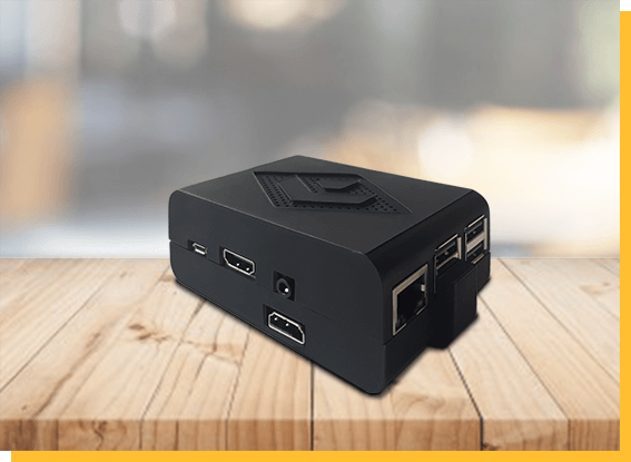
According to ClearCube, the compact C3xPi Thin Client is the only low-cost, virus-proof, single-case dual monitor thin client in the market. The 0 to 35°C device is equipped with 2x HDMI 3.1 ports for dual simultaneous displays with a 1920 × 1080 video resolution. The second HDMI port is hinted to make use of the Pi’s MIPI-DSI interface since ClearCube has not released a statement on how its “patent pending” technology drives the second HDMI port.
ClearCube supports the Citrix HDX virtual desktop environment, through its Cloud Desktop OS. The Citrix HDX is enabled through the incorporation of the Citrix Workspace Hub and supports hardware-accelerated H.264 decoding for dual monitors. ClearCube says it also lowers CPU consumption by offloading video decompression from its CPU to its native hardware. At 3.75 x 2.31 x 1.25-inch, the device reveals all the ports of the RPi 3B+. One of the 4x USB ports has been replaced to accommodate the second HDMI port. RPi 3B+ enhancements available through here include the faster, 1.4GHz Broadcom BCM2837B SoC. Also available is the new Gigabit Ethernet port, which has faster performance than how it used to perform, but is limited due to its USB interface to 300Mbps.
Additional features include a 1GB LPDDR2 RAM, an 8GB microSDHC card, a 3.5mm audio jack, and a Kensington security slot. The device ships with a 12V power supply and a VESA kit for attachment to the back of a monitor. There is also a 3B+’s faster, a pre-certified wireless module with 2.4GHz/5GHz 802.11.b/g/n/ac and Bluetooth 4.2 BLE available. The C3xPi Thin Client is available for $179.95.
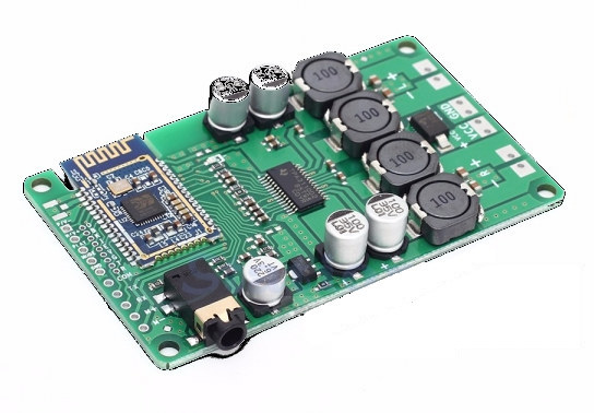
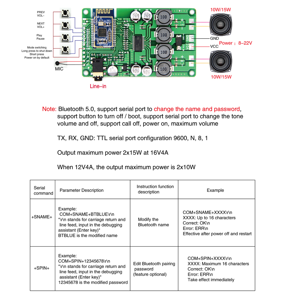
IC station has posted a $10.59 audio amplifier board that supports Bluetooth 5.0 via Beken BK3266 Bluetooth audio chip. For the board to work, you will have to connect buttons, a microphone and 10W or 15W speakers. The hardware setup has to be completed with a power source and an optional input audio signal. After setting it up, the board is ready to be paired with a Bluetooth device. A USB can be connected to the TTL debug board to configure the board over UART.
The board is suitable for a wide range of uses, like a DIY speaker, voice intelligent control, Bluetooth signal conversion, stereo Bluetooth speaker or headset, Bluetooth hands-free calling, Bluetooth control, to mention a few. The “Bluetooth 5 enables serial port interface to change name and password, a button to turn off or boot, serial port interface to change the tone volume, support call off, power on, maximum volume”, which don’t seem specifically related to BT 5.0. Version 5.0 supports a longer range of about 10m and this does not utilize its long-range feature. According to Bluetooth 5 specifications, Bluetooth 5 has the capability to carry out periodic data to be broadcasted, enabling chain packets and deterministic advertising.
This enables the scanners to function together and for each packet to contain different synchronization to scan for packets with the subset of the whole data set and schedule of the advertising device. This feature gives room for a more power-efficient way to perform scanning and might create room for new applications of Bluetooth LE in connection-less scenarios, such as audio applications. The advertising extensions feature is laying the groundwork for next-generation beacons, advanced audio applications, to mention just a few.
Bluetooth 5 also introduced a new channel selection algorithm called channel selection algorithm #2. Frequency hopping is pseudo-random and the distinct sequences which are possible are very large. If Bluetooth 5 LE is to be used for audio applications, one can expect a longer battery life due to the lower power consumption. This means that audio cuts are less likely to occur, and the improvement carried out on the Bluetooth 5 advertising extensions should reduce re-connection time.
It is unknown if BK3266 supports any of those “features” listed on the Bluetooth 5 specifications and that’s because Beken hasn’t updated their website with any info about the new chip, and data sheet is not available online.
Specifications and features listed for the board include:
Bluetooth 5.0 Connectivity
Up to 6 paired devices
Bluetooth protocols – HFPV1.7, A2DPV1.2, AVRCPV1.5, AVCTPV1.2, AVDTPV1.2 Range up to 10 meters
Transmission Power – Class2, 4dbm
Sensitivity – -81dBm < 0.1% BER
FrequencyRange – 2.402GHz – 2.480GHz
Audio- MP3/WMA/WAV music format
SpeakerImpedance – 4 to 8 Ohm
OutputPower – 2x15W at 16V/4A, 2x10W at 12V/4A
Audio signal to noise ratio >75dB
Configuration via UART interface
Misc – On/off button
Supply Voltage – 8.0 to 22.0 V DC
Power Consumption – Working current <=20mA; standby current <500uA
Dimensions – 71 x 53 x 9.4 mm
Temperature Range -20℃ to 85℃
Relative Humidity– 0% to 95%
The board can be purchased on ICStation and is currently on sale for $7.39.
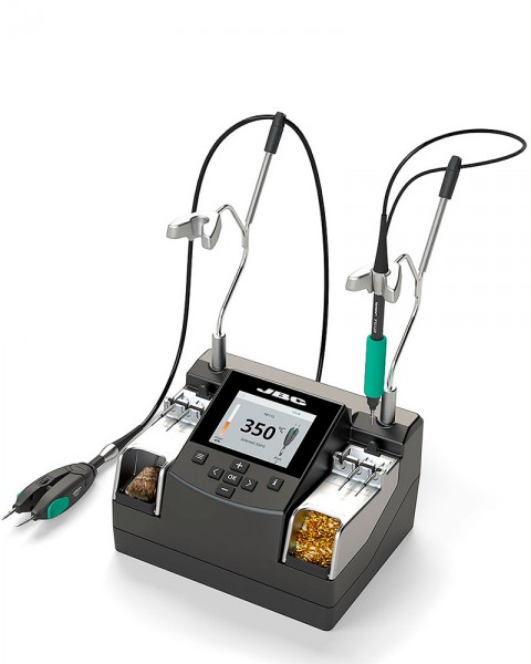
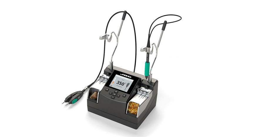
NASE 2 Tools Nano Rework station is one of the best solutions for soldering and rework of SMD components requiring the highest precision. It works simultaneously with the NT115-A Nano Handpiece and the AN115 Steady Nano Tweezers. The short distance from the tip to the handle offers maximum control even when using a microscope.
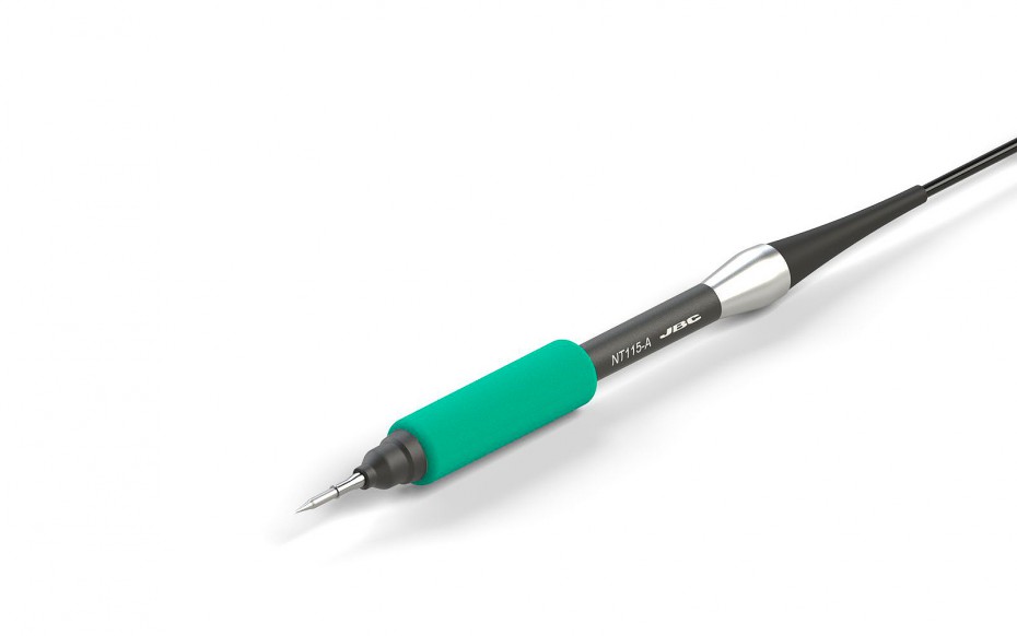
NT115-A Nano Handpiece
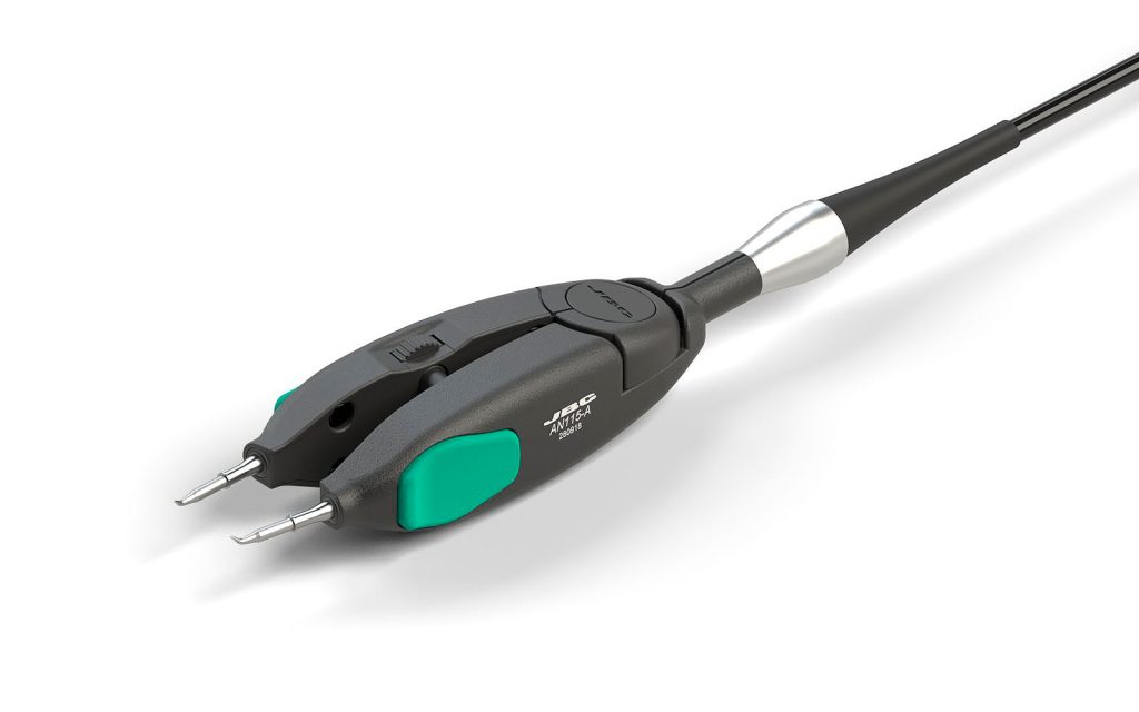
AN115 Steady Nano Tweezers
Temperature Dynamic Profiles
The NASE-C comes with the new Temperature Dynamic Profiles functionality. The use of these profiles allows you to control the temperature of the component during all the phases of the soldering process, emulating the heating process in a reflow oven.
Its easy to use menu is configurable in 10 different languages: English, German, Spanish, French, Italian, Portuguese, Russian, Japanese, Korean and Chinese.
The NASE-C Rework Station works with the C115 Cartridge Range.
Specifications
Temperature: 90 to 450 ºC / 190 to 840 ºF
Dynamic Soldering Profiles: Designed to avoid thermal shock when soldering Ceramic Chip components like MLCC, this new and unique feature allows controlling the heating ramp up rate of the tool to gradually increase the temperature of the component through all the phases of the soldering process.
Up to 25 fully configurable soldering profiles can be stored.
Special features
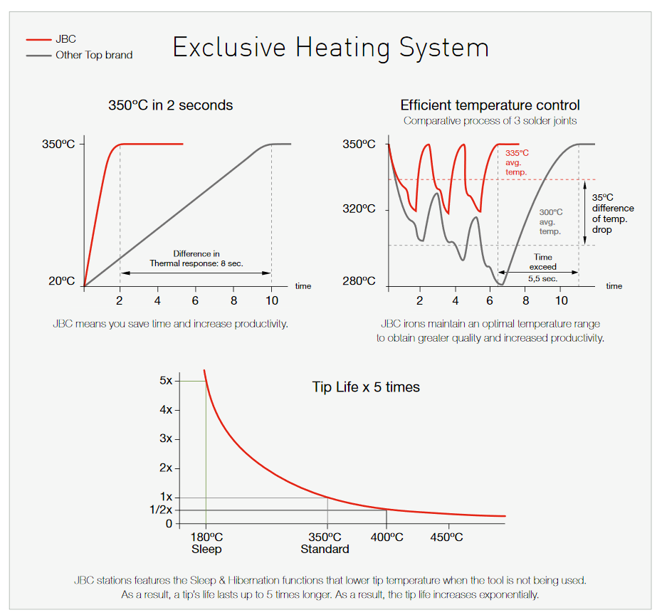
Sleep and Hibernation mode: These modes lower soldering tip temperature when the tool rests in the stand in order to avoid oxidation and extending tip life.
Max. and min. temperature: Limit the temperature range in which the operator is allowed to work.
Temperatue levels: Instant selection of up to 3 editable temperature settings for solder joints with different heat requirement.
Soldering graphics: Real time visualization of tip temperature and power delivered to the solder joint during soldering process.
PIN protection: Keep station parameters protected against unauthorized access.
We’ve done quite a number of tutorials on the use of several displays with Arduino boards and today we will add another tutorial to that list. We will look at the ILI9325 based 2.8″ touchscreen display shown below and how it can be used with the Arduino to deliver a better user experience for your projects.
Geekcreit 2.8 Inch Touchscreen Display
For today’s tutorial, we will use the ILI9325 driver based, 2.8″ display from Geekcreit. The display comes as a shield so it’s ready to be used for Arduino based projects. It is an 18-bit color display with a total of 262,000 different color shades. The display has a resolution of 240 x 320 pixels with individual pixel control.
Today’s project involves some very simple tasks which we will use to demonstrate the capabilities of the display. We will create a button which when touched, will trigger the Arduino to display a message on the screen. At the end of today’s tutorial, we would have gone through how to create a user interface on the touchscreen, how to detect when the screen is touched and how to display data on the screen.
Required Components
The following components/parts are required to build this project:
The Arduino Mega or any of the other Arduino board can be used for this project and the power bank comes in handy when the project is to be used in a standalone mode. As usual, the exact components used for this tutorial can be purchased via the links attached to each of them.
Schematics
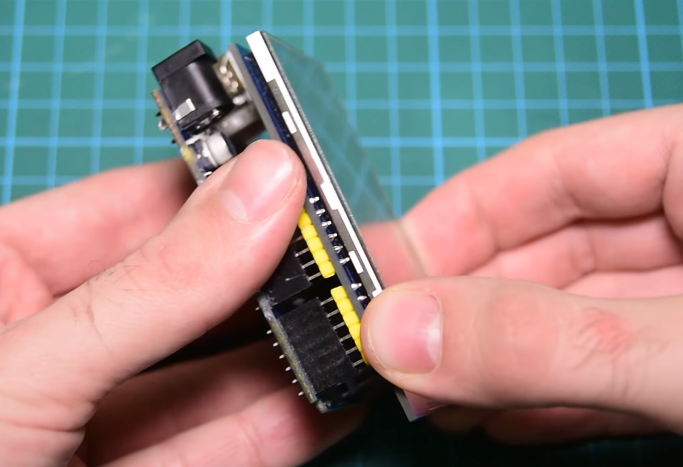
The 2.8″ TFT display used for this project comes as a shield with the form factor of the Arduino Uno. This makes it easy to connect the shield to boards like the Uno, Mega and Due, as all we need to do, is plug it directly into the board, eliminating all the mess made by wires. Plug the display to the Arduino as shown in the image below.
Connect display to Arduino
The fact that the display comes as a shield becomes a disadvantage when its used with the Arduino Uno as it occupies almost all the pins leaving just 2 digital pins and one analog pin for other uses. This can however, be overcome by using either the Arduino Mega or Due as they both work perfectly well with the display.
Code
The code for this tutorial is heavily reliant on a modified version of Adafruit’s TFT LCD, GFX and touchscreen libraries. These libraries can be downloaded from the links attached to them.
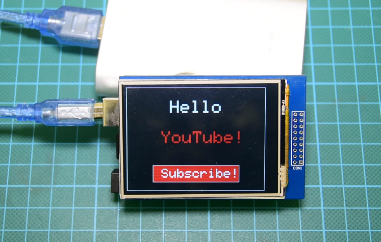
As mentioned earlier, our focus for this tutorial will be to demonstrate, how UI can be created on the display and interpret touches to trigger actions. To achieve this, we will develop a simple sketch which displays a Youtube subscribe button. When the subscribe button is pressed, a text is displayed on the screen.
To do a quick run through the code, we will start by including the libraries that will be used for the project.
//Written by Nick Koumaris
// info@educ8s.tv

#include <Adafruit_TFTLCD.h>
#include <Adafruit_GFX.h>
#include <TouchScreen.h>
Next, we declare the pins of the Arduino to which the display is connected.
Calibration needs to be done before the touchscreen functionality of this display can be used. To calibrate the screen, we upload the code and Open the Serial Monitor to obtain the values of the display’s edges. Click (touch) on the top left corner of the display and write down the X and Y values displayed on the serial monitor. Then we edit the code to reflect those values. The X value goes to the TS_MAXX variable and the Y value goes to the TS_MAXY variable. Next, click on the bottom right corner of the display and enter the values displayed on the serial monitor for the TS_MINX and TS_MINY variables. With this done our display is now calibrated and ready for use.
Next, we declare the colors to be used with their hexadecimal values and we create an object of the Adafruit TFTLCD library, indicating the variables used to represent the pins of the Arduino to which the display is connected.
#define BLACK 0x0000
#define BLUE 0x001F
#define RED 0xF800
#define GREEN 0x07E0
#define CYAN 0x07FF
#define MAGENTA 0xF81F
#define YELLOW 0xFFE0
#define WHITE 0xFFFF
Adafruit_TFTLCD tft(LCD_CS, LCD_CD, LCD_WR, LCD_RD, LCD_RESET);
We also create an object of the touchscreen library indicating, the pins of the Arduino to which, the touch part of the screen is connected.
We start by initializing the serial monitor and the display. After this, we set the orientation of the LCD and fill the screen with a black color to serve as the background.
next, we draw a white frame on the display, set the text cursor to the desired location, change its color to white, and print the “Hello” text on the screen. By following the same procedure, we display the red YouTube text as well.
//Draw white frame
tft.drawRect(0,0,319,240,WHITE);
//Print "Hello" Text
tft.setCursor(100,30);
tft.setTextColor(WHITE);
tft.setTextSize(4);
tft.print("Hello");
//Print "YouTube!" text
tft.setCursor(80,100);
tft.setTextColor(RED);
tft.setTextSize(4);
tft.print("YouTube!");
Next, we create the red Youtube subscribe button. To achieve this, we create a red rectangle and for our size requirements, we set the x and y pixel coordinates of the top left corner point of this rectangle to (60,180), define its width as 200 pixels, its height as 40 pixels and set pixel coordinates for the bottom right of the rectangle to (260, 220). To make the rectangle look more like a button, we draw a similar white rectangle outside of the red rectangle and write the “Subscribe” text on it.
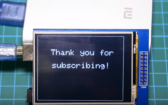
With the setup function all done, we move to the loop function, the algorithm in operation for the loop section is simple, each time the user clicks on the screen, we convert the point coordinates of the touch point into pixels using the Map function. After conversion, if that point is inside the red rectangle area, it means that the user has pressed the button, so we disable the button by setting this variable to false and we clear the screen so to display the “Thank you for Subscribing” message on the screen.
void loop()
{
TSPoint p = ts.getPoint(); //Get touch point
if (p.z > ts.pressureThreshhold) {
Serial.print("X = "); Serial.print(p.x);
Serial.print("\tY = "); Serial.print(p.y);
Serial.print("\n");
p.x = map(p.x, TS_MAXX, TS_MINX, 0, 320);
p.y = map(p.y, TS_MAXY, TS_MINY, 0, 240);
if(p.x>60 && p.x<260 && p.y>180 && p.y<220 && buttonEnabled)
// The user has pressed inside the red rectangle
{
buttonEnabled = false; //Disable button
//This is important, because the libraries are sharing pins
pinMode(XM, OUTPUT);
pinMode(YP, OUTPUT);
//Erase the screen
tft.fillScreen(BLACK);
//Draw frame
tft.drawRect(0,0,319,240,WHITE);
tft.setCursor(50,50);
tft.setTextColor(WHITE);
tft.setTextSize(3);
tft.print("Thank you for\n\n subscribing!");
}
delay(10);
}
}
The complete code for this project is below and also attached under the download section.
//////////////////////////////////////////////
// 2.8" TOUCH SCREEN DEMO //
// //
// http://www.educ8s.tv //
/////////////////////////////////////////////
#include <Adafruit_TFTLCD.h>
#include <Adafruit_GFX.h>
#include <TouchScreen.h>
#define LCD_CS A3
#define LCD_CD A2
#define LCD_WR A1
#define LCD_RD A0
#define LCD_RESET A4
#define TS_MINX 204
#define TS_MINY 195
#define TS_MAXX 948
#define TS_MAXY 910
#define YP A2 // must be an analog pin, use "An" notation!
#define XM A3 // must be an analog pin, use "An" notation!
#define YM 8 // can be a digital pin
#define XP 9 // can be a digital pin
#define BLACK   0x0000
#define BLUE    0x001F
#define RED     0xF800
#define GREEN   0x07E0
#define CYAN    0x07FF
#define MAGENTA 0xF81F
#define YELLOW  0xFFE0
#define WHITE   0xFFFF
Adafruit_TFTLCD tft(LCD_CS, LCD_CD, LCD_WR, LCD_RD, LCD_RESET);
TouchScreen ts = TouchScreen(XP, YP, XM, YM, 300);
boolean buttonEnabled = true;
void setup() {
  Serial.begin(9600);
  Serial.print("Starting...");

  tft.reset();
  tft.begin(0x9325);
  tft.setRotation(1);

  tft.fillScreen(BLACK);
//Draw white frame
  tft.drawRect(0,0,319,240,WHITE);

  //Print "Hello" Text
  tft.setCursor(100,30);
  tft.setTextColor(WHITE);
  tft.setTextSize(4);
  tft.print("Hello");

  //Print "YouTube!" text
  tft.setCursor(80,100);
  tft.setTextColor(RED);
  tft.setTextSize(4);
  tft.print("YouTube!");
//Create Red Button
  tft.fillRect(60,180, 200, 40, RED);
  tft.drawRect(60,180,200,40,WHITE);
  tft.setCursor(80,188);
  tft.setTextColor(WHITE);
  tft.setTextSize(3);
  tft.print("Subscribe!");
}
void loop()
{
TSPoint p = ts.getPoint(); //Get touch point
if (p.z > ts.pressureThreshhold) {
Serial.print("X = "); Serial.print(p.x);
Serial.print("\tY = "); Serial.print(p.y);
Serial.print("\n");
p.x = map(p.x, TS_MAXX, TS_MINX, 0, 320);
p.y = map(p.y, TS_MAXY, TS_MINY, 0, 240);
if(p.x>60 && p.x<260 && p.y>180 && p.y<220 && buttonEnabled)// The user has pressed inside the red rectangle
{
buttonEnabled = false; //Disable button
//This is important, because the libraries are sharing pins
pinMode(XM, OUTPUT);
pinMode(YP, OUTPUT);
//Erase the screen
tft.fillScreen(BLACK);
//Draw frame
tft.drawRect(0,0,319,240,WHITE);
tft.setCursor(50,50);
tft.setTextColor(WHITE);
tft.setTextSize(3);
tft.print("Thank you for\n\n subscribing!");
}
delay(10);
}
}
Demo
Copy the code above and create a new Arduino sketct. Ensure the libraries are installed and upload the code to the setup described under the schematics section. Once the upload is complete, you should see the display come up as shown below.
Demo
As soon as the subscribe button is pressed, the screen below is displayed.
Demo
That’s it for this tutorial guys. Feel free to expand this code for use in your projects and do not hesitate to let me know via the comment section if you have any questions.
The Internet of Things (IoT) is creating many new exciting application opportunities to create smart environments where sensors monitor for changes so that the appropriate actions can be taken. The fastest growing examples of this are HVAC (Heating Ventilation and Air Conditioning), IAQ (Indoor Air Quality), smart homes and smart offices where a network of sensors monitors temperature and carbon dioxide (CO2) levels to ensure the optimal conditionals are maintained with the minimum of energy expenditure. A challenge for such systems in that the CO2 sensors need mains power to operate incurring costs for cabling and, in the case of installing in existing buildings, redecoration.
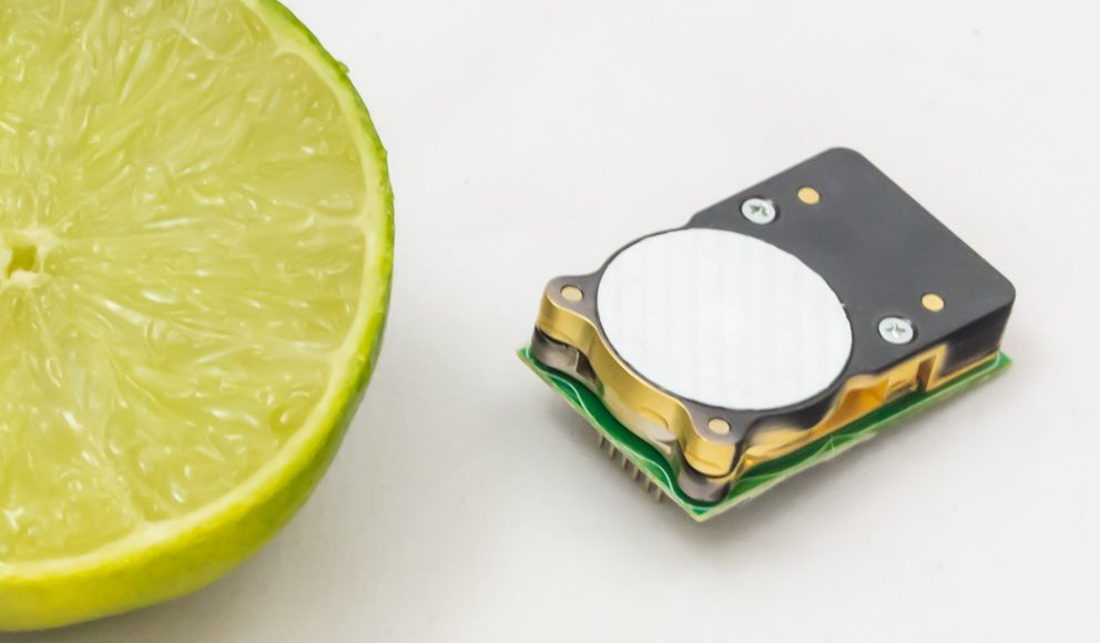
Gas Sensing Solutions (GSS) has solved this problem with its low power, LED-based sensor technology. The sensor’s power requirements are so low that wireless monitors can be built that measure CO2 levels as well as temperature and humidity with a battery life of over ten years. Being wireless means that they can be placed wherever they are required with no need for cabling or disruption and simply relocated as building usages changes
To make the design of these monitors even easier, GSS has added an I2C interface to its very low power CO2 sensor, the CozIR®-LP. Having the widely used I2C interface now makes the integration of the sensor into a design very easy. The CozIR®-LP is the lowest power CO2 sensor available requiring only 3mW that is up to 50 times lower than typical NDIR CO2 sensors. The GSS patented LED technology also means that the solid state sensor is very robust. This keeps maintenance costs to a minimum as the expected lifetime is greater than 15 years making them the perfect choice for fit and forget applications that measure low (ambient) levels of CO2 from 0-1%.
Calum MacGregor, CEO at GSS, explains:
Although HVAC and IAQ are major application areas, the lightweight, miniature size of the CozIR-LP also opens up other new possibilities for CO2 monitoring such as portable and wearable devices. The power requirements are so low that energy harvesting designs, such as solar, are now easily achievable. Here again, the new feature of an I2C interface will simplify the design process of integrating the sensor with other sensors and devices all on the I2C bus.
GSS will be launching the new I2C-enabled CozIR®-LP on booth C5366 at the AHR Expo in Atlanta, GA, USA on the 14-16 of January 2019. https://ahrexpo.com/
GSS technology
Most CO2 sensors work by measuring how much light is absorbed by CO2 molecules in the 4.2 to 4.4 microns range as it passes through the sample gas, which is called Non-Dispersive Infra Red (NDIR) absorption. The amount of absorption indicates how much CO2 is present. GSS developed proprietary LEDs that are specifically tuned to emit at these wavelengths. The LEDs use very little power and turn on almost instantly, enabling sensor readings to be made in a few seconds. As a result, GSS has pioneered the development of CO2 sensors that can be powered by batteries for long periods of up to ten years. Competitor sensors use IR sources that require significantly more power per measurement and also take much longer to reach a stable condition for a measurement, resulting in the need for mains power.
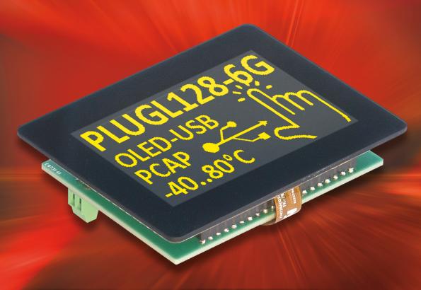
For the first time, ELECTRONIC ASSEMBLY presents the EA PLUGL128, a touch-sensitive OLED display that can be addressed directly via USB. It offers a resolution of 128 × 64 pixels with a 2.9″ screen diagonal. Since OLED technology enables each pixel to act as an independent light source, there is no angle-dependent contrast attenuation as is the case with LCD displays. The contrast of at least 2,000:1 remains constant over the entire viewing angle range of 170°. The display is extremely fast and still reacts smoothly and without delay even at temperatures as low as -40°C. The display is also extremely easy to read. It is protected by a robust, touch-sensitive glass pane. A gentle touch is all it takes to change displays or trigger actions.
Various graphic functions and character sets with German diacritics are already implemented. Thanks to various digital inputs and outputs, the display can take over small control tasks independently. Communication with microcontroller applications can take place via SPI, I2C or RS-232 interfaces. These are bidirectional and designed for 3.3V levels.
Version with screw terminals
In the Z version (EA PLUGL128-6GTCZ), the OLED display also features twelve screw terminals. External sensors or detectors can thus be connected easily and reliably. Two analog inputs enable voltage measurement up to 3.3V with direct display indication. In addition, this version is equipped with a 26-pin IDC tray connector, which provides additional I/Os and serial interfaces.
Possible applications include home automation and the upgrade of applications with text displays, as well as the control of smaller equipment.
EA PLUGL128 is the first member of the new display family EA PLUGxxx. Displays with 1.6″ and 2.2″ screen diagonals will soon also be available.
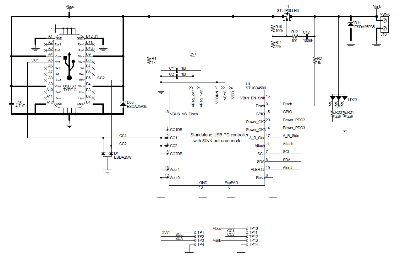
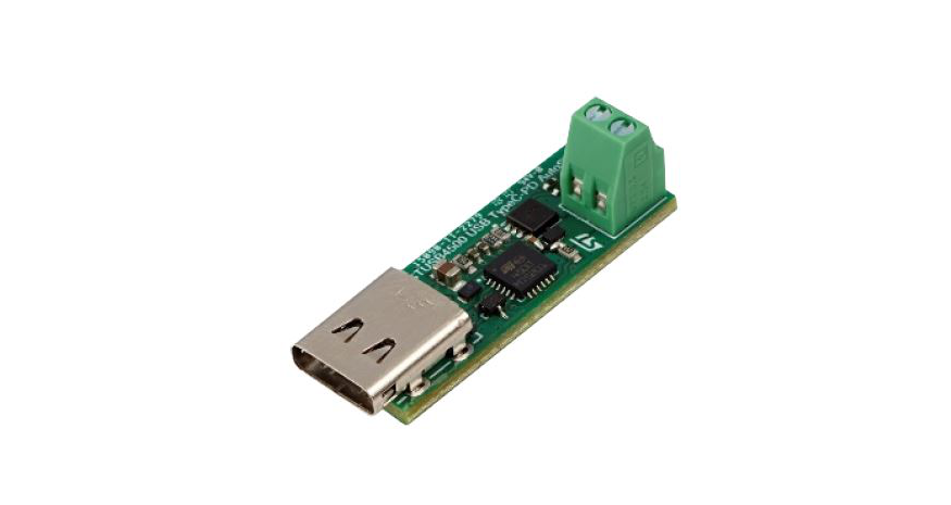
The STREF-SCS001V1 reference design lets you create a USB Type-C connector quickly and easily in order to power any application up to 100W (20 V, 5 A).
Key Features
USB Power Delivery SINK port
short-to VBUS protection up to 28 V
low BOM cost, small footprint
Status LED
Schematic
STREF-SCS001V1 Schematic
Video
The evaluation board isn’t for sale at this moment. Will be available soon.
[Update 07-02-2019] more information on this ST blog post.
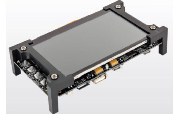
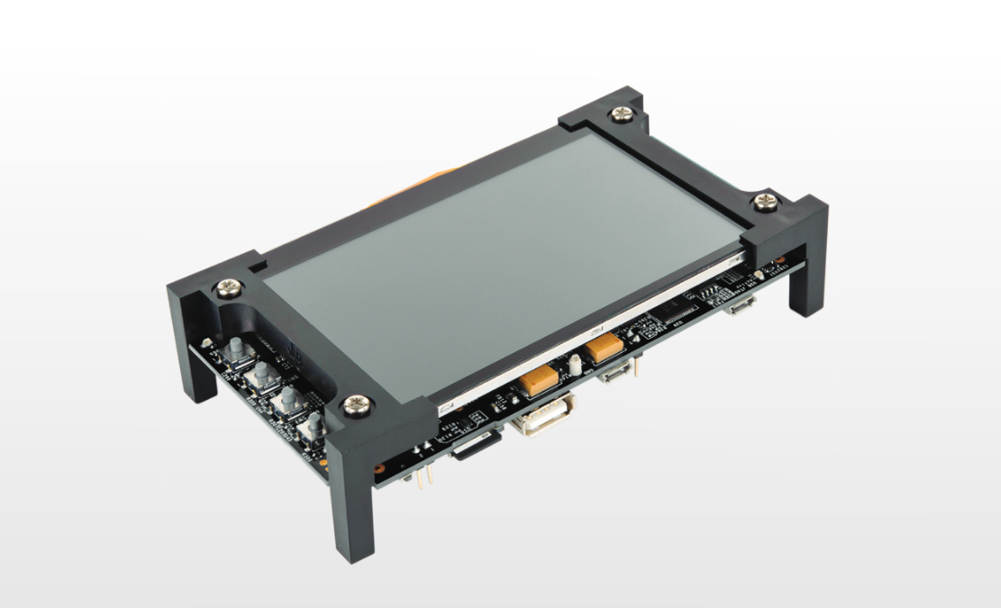
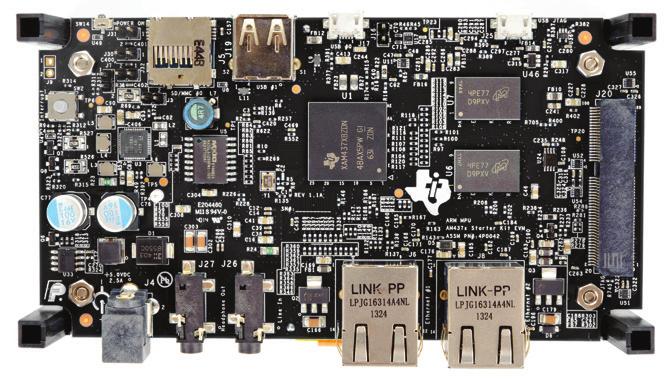
The AM437x Starter Kit provides a stable and affordable platform to quickly start evaluation of Sitara™ ARM® Cortex®-A9 AM437x Processors (AM4376, AM4378) and accelerate development for HMI, industrial and networking applications. It is a low-cost development platform based on the ARM Cortex-A9 processor that is integrated with options such as Dual Gigabit Ethernet, DDR3L, Camera and Capacitive Touch Screen LCD.
At speeds up to 1 GHz, the AM437x Starter Kit accelerates designs with a ready-for-production hardware and software platform. This “best value” board offers the ability to quickly evaluate the features of the processor and accompanying TI components, taking the guess work out of the hardware design and allowing both experienced and novice designers to focus on product differentiation such as advanced graphics and connectivity.
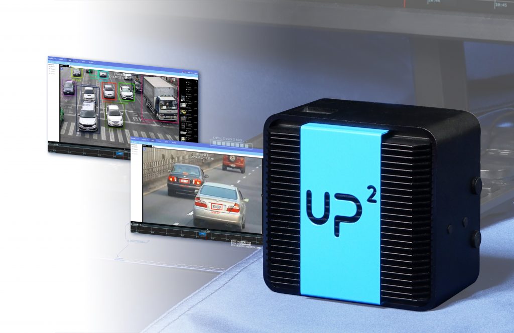
AAEON, the leading designers and manufacturers of IoT and A.I. edge computing platforms, and Gorilla Technology Group, the global leader specializing in video intelligence and IoT technology, jointly demonstrated their A.I. (artificial intelligence) computing capability in featured smart transportation solutions at Intel® booth during CES 2019.
CES (Consumer Electronics Show) is the world stage of leading technological innovations, annually held in U.S.A. This time, AAEON and Gorilla Technology were invited by Intel to jointly showcase their edge A.I. computing capability.
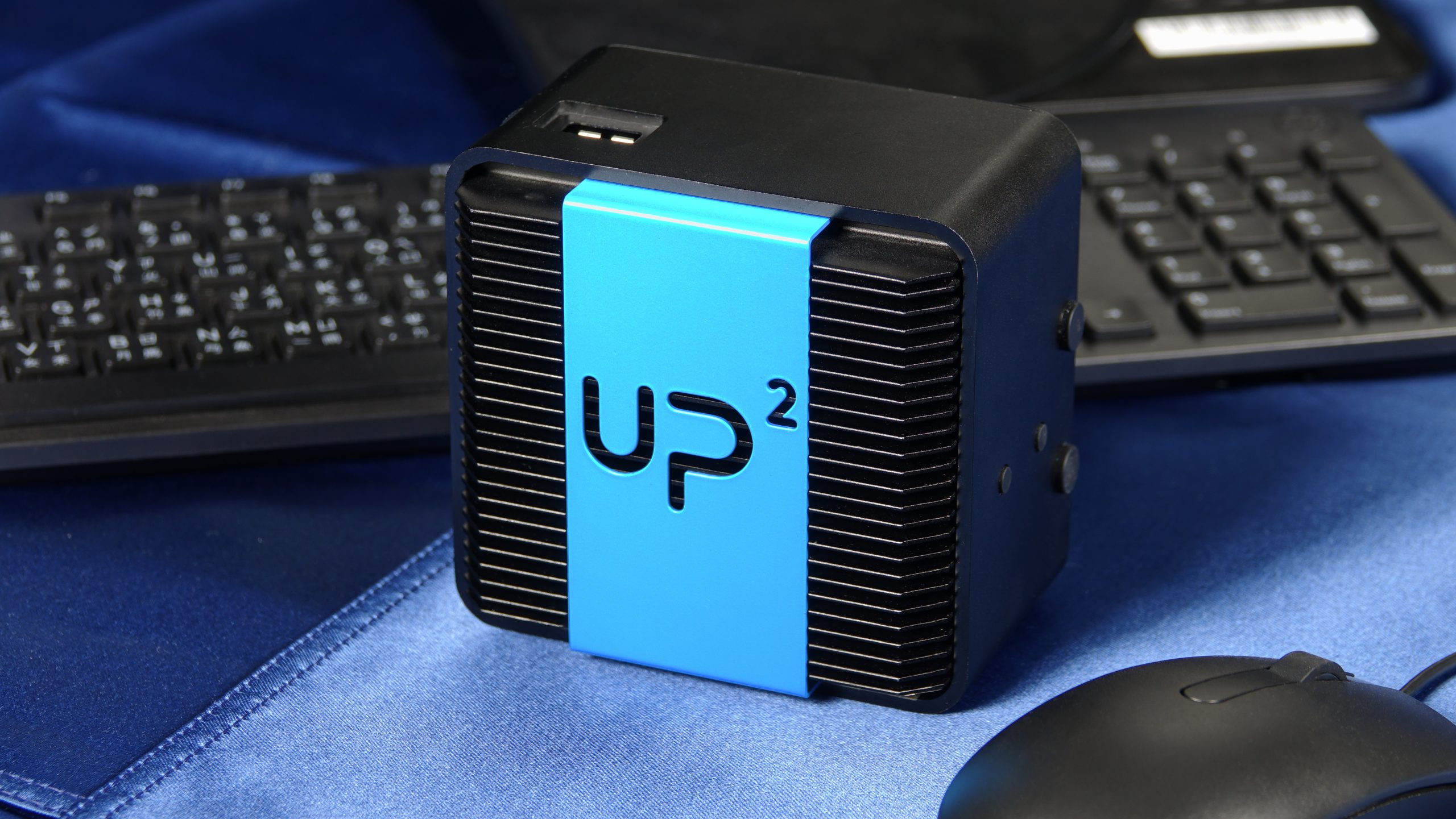
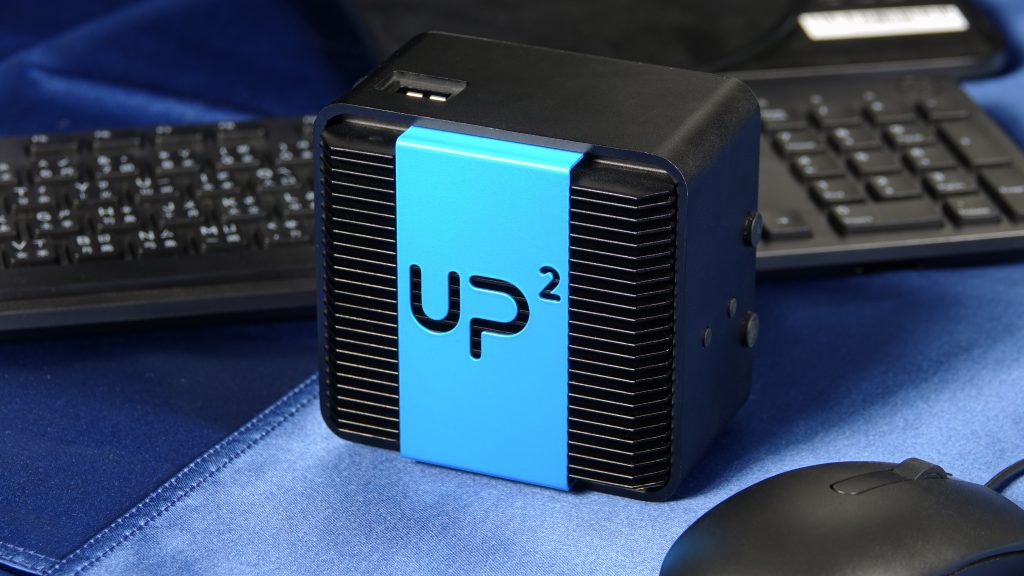
The theme of Gorilla – AAEON demonstration was dedicated in smart transportation. AAEON’s UP2 board was integrated with Gorilla’s IVARTM (Intelligent Video Analytics Recorder) software and Intel® OpenVINO technology to realize license plate recognition, vehicle model recognition, vehicle tracking and traffic analysis from the video streams of two cameras.
It is our pleasure to work with Gorilla Technology to demonstrate our edge A.I. computing capability in smart transportation at the Intel® booth during CES 2019. Our UP2 with AI Core X, the mini-PCI Express card based on Intel® Myriad X, proved to be widely applicable. Currently, our UP2 has been deployed in smart retail, smart factory and construction site safety. With the support of Gorilla’s IVARTM software, we successfully applied it in smart transportation. We will continue our partnership with Gorilla to develop more A.I. and IoT solutions for our customers
said Victor Lai, Director of Design Manufacturing Service Division of AAEON.
Consumer Electronics Show (CES) Information:
Date: Jan. 8-11, 2019
Venue: Las Legas, NV. (Tech East, Tech West, and Tech South)
Intel booth: LVCC, Central Hall – 10048
About Gorilla Technology
Gorilla Technology, a privately held company established in 2001, is a global leader in video intelligence, network intelligence and IoT technology. They develop a wide range of video-centric and content management applications including Smart Retail, Smart School, Smart Enterprise, Smart Surveillance and broadcast media. In addition, Gorilla provides a complete security convergence solution to government institutes, telecom companies and private enterprises with network surveillance and cyber security.
About AAEON
Established in 1992, AAEON is one of the leading designers and manufacturers of professional intelligent IoT solutions. Committed to innovative engineering, AAEON provides reliable and high quality computing platforms, including industrial motherboards and systems, industrial displays, rugged tablets, embedded controllers, network appliances and related accessories, as well as integrated solutions. AAEON also has the hardware and services for premier OEM/ODMs and system integrators worldwide. As an Associate Member of the Intel® Internet of Things Solutions Alliance, AAEON offers customized end-to-end services from initial product conceptualization and board product development to mass manufacturing and after-sales service programs. For an introduction to AAEON’s expansive line of products and services, visit www.aaeon.com.
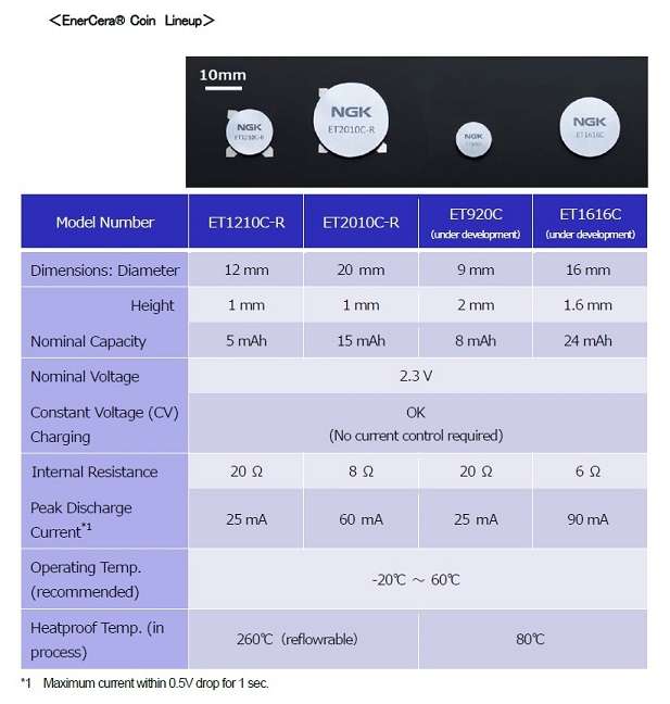
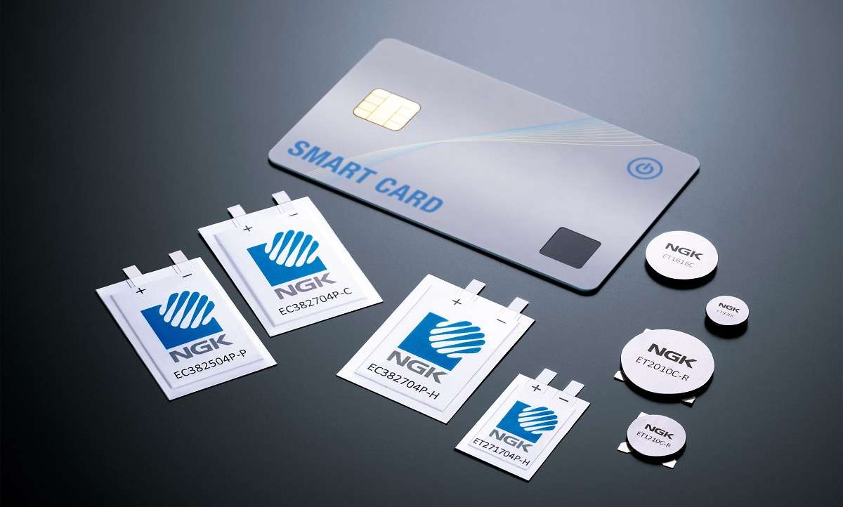
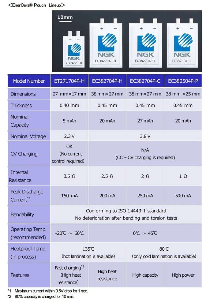
Ultra-small, ultra-thin, high-capacity and capable to be installed at high temperatures, the EnerCera line of rechargeable Li-ion batteries is looking to change up the market for IoT devices by being adaptable to current manufacturing processes while allowing wireless communication. (via)
The key lies in the usage of ceramic, in the form of Japanese manufacturer NGK Insulators (hereafter NGK) original Crystal Oriented Ceramic Plate as electrodes, allowing for the battery to be composed of just an active material, containing no organic binder or conductive material and making the high energy density and low internal resistance possible.
Technology solutions that respond to current demands
Discussing the potential of this new line of batteries, General Manager and Project Leader for R&D, Iwao Ohwada pointed to the fact that
in the current state of the IoT market, there is strong demand for small batteries with high functionality. The reason for that is simple: battery technology is lagging behind. Batteries take up space, their life-span is short, maintenance is difficult. This makes up a big obstacle to the explosion of IoT. I think that our devices can overcome these difficulties. They are ultra-thin, easy to implement, and maintenance free. In that sense, we have overcome the walls limiting batteries and created a new paradigm for the concept of what a battery can be. I believe this has the potential to have a ripple effect for the market as a whole.
Consider one of the central issues of IoT devices: the need for large currents (several 10 mA to several 100 mA) to support wireless communications. By allowing for this while simultaneously realizing CV (Constant Voltage)-charging capability, this line of batteries allows for smaller, more efficient devices with a larger lifespan.