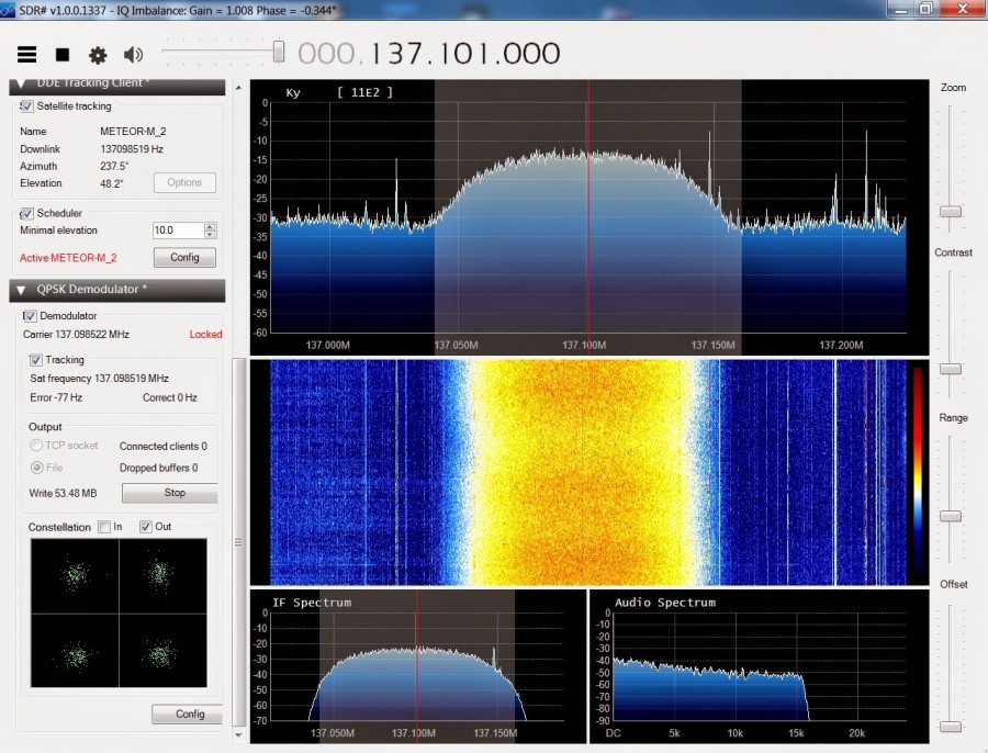
The Meteor-M N2 is a polar orbiting Russian weather satellite that was launched on July 8, 2014. Its main missions are weather forecasting, climate change monitoring, sea water monitoring/forecasting and space weather analysis/prediction. Meteor-M N2 transmits images using the digital LRPT protocol at around 137.1 MHz with can be received with an RTL-SDR. The chipset of RTL dongles was created with the intention of doing DVB-T (digital TV) and DAB (digital radio) demodulation , however a curious linux developer named Antti Palosaari, discovered that these cheap TV adapters are actually Sofware Defined Radios (SDR)!
Decoding Russian Meteor-M2 satellite images in real time – [Link]
While building microcontroller based projects, there are occasions where communication will be required between two devices, either in a duplex/transceiver based operation (where both devices can transmit and receive at the same time) or in a simplex-based operation where communication is one way (Receiving device cannot transmit and the transmitting device cannot receive).
Several options exist for implementing any of the two communication modes mentioned above and the selection of a particular option, usually depends on the specification of the project, especially the distance between the devices and cost. For short range, low-budget communication between two microcontrollers, one of the most preferred medium used is Radio Frequency (RF) communication using the 433MHz RF transmitter and receiver modules. For today’s tutorial, we will look at how to use these modules to establish communication between two Arduino boards.
Using the 433MHz RF Transmitter and Receiver with Arduino – [Link]
While building microcontroller based projects, there are occasions where communication will be required between two devices, either in a duplex/transceiver based operation (where both devices can transmit and receive at the same time) or in a simplex-based operation where communication is one way (Receiving device cannot transmit and the transmitting device cannot receive).
Several options exist for implementing any of the two communication modes mentioned above and the selection of a particular option, usually depends on the specification of the project, especially the distance between the devices and cost. For short range, low-budget communication between two microcontrollers, one of the most preferred medium used is Radio Frequency (RF) communication using the 433MHz RF transmitter and receiver modules. For today’s tutorial, we will look at how to use these modules to establish communication between two Arduino boards.
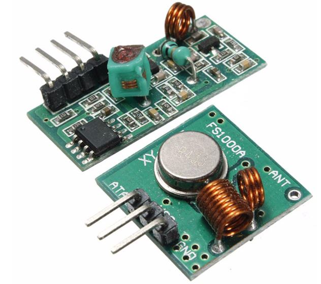
The 433 MHz Transmitter and Receiver Modules
433 MHz RF Transmitter and Receiver Module
These modules are very popular among makers and DIY enthusiasts due to their low cost and ease of use. They are used in all forms of short-range, simplex-based communication between two microcontrollers with one of the microcontroller serving as the transmitter while the other serves as the receiver. These modules are ASK (Amplitude Shift Keying) or OOK (Of Hook Keying) type RF modules, that means they usually draw no power when transmitting a Logic “zero” and as such consumes a significantly low amount of power. This low power consumption makes them very useful in battery-based implementations.
Some of the specifications of the transmitter and receiver modules are listed below.
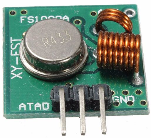
Transmitter Specifications
433 MHz RF transmitter
Working voltage: 3V – 12V
Working current: max Less than 40mA max, and min 9mA
Resonance mode: (SAW)
Modulation mode: ASK
Working frequency: 433.92MHz
Transmission power: 25mW
Frequency error: +150kHz (max)
Velocity: less than 10Kbps
Transmission range: 90m (in open space)
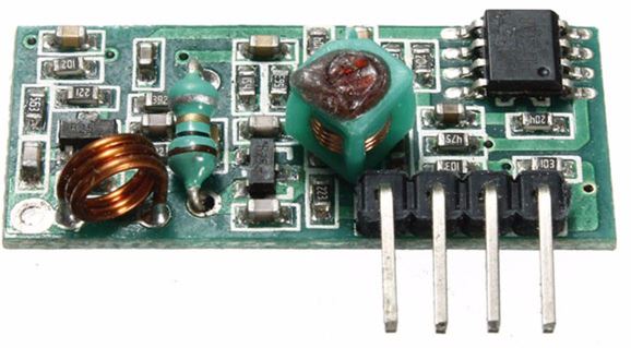
Receiver Specifications
433MHz Receiver Module
Working voltage: 5.0VDC +0.5V
Working current:≤5.5mA max
Modulation mode: OOK/ASK
Working frequency: 433.92MHz
Bandwidth: 2MHz
Sensitivity: exceeds –100dBm (50Ω)
To demonstrate the ease with which wireless capabilities can be added to projects using these modules, we will build a weather station with remote data display. The weather station will comprise primarily of a temperature and humidity sensor and the 433 RF transmitter module. It will measure the temperature and humidity of the environment and send it via the RF transmitter to the display unit (received via the RF receiver module) on a ST7735 1.8″ Color TFT LCD display.
Required Components
The following components are required to build this project:
As usual, all of these components can be bought via the links attached above.
Schematics
There are two schematics for this project. The first one is for the transmitter which obtains temperature and humidity from the environment and sends it to the second half of the project, the receiver, which displays the data on the display.
Schematic for the Transmitter
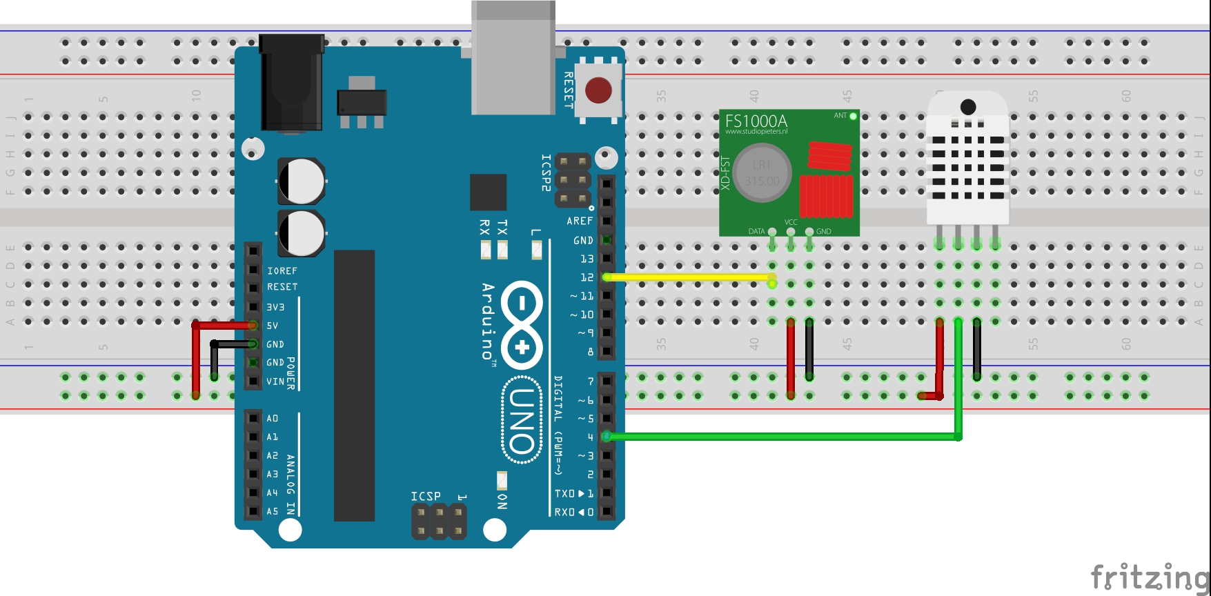
The transmitter circuit comprises of an Arduino, the DHT22 temperature and humidity sensor, and the 433 MHz RFtransmitter module. A battery pack can be added to provide power to the Arduino when its disconnected from the computer. Connect the components as shown below.
Transmitter Schematics
For clarity, the pin connections between the Arduino and the other components are displayed below.
Arduino – 433 MHz Tx Module
5V - VCC
12 - Data
GND - GND
Arduino – DHT22
5V - VCC
D4 - Signal
GND - GND
Schematics for the Receiver Circuit
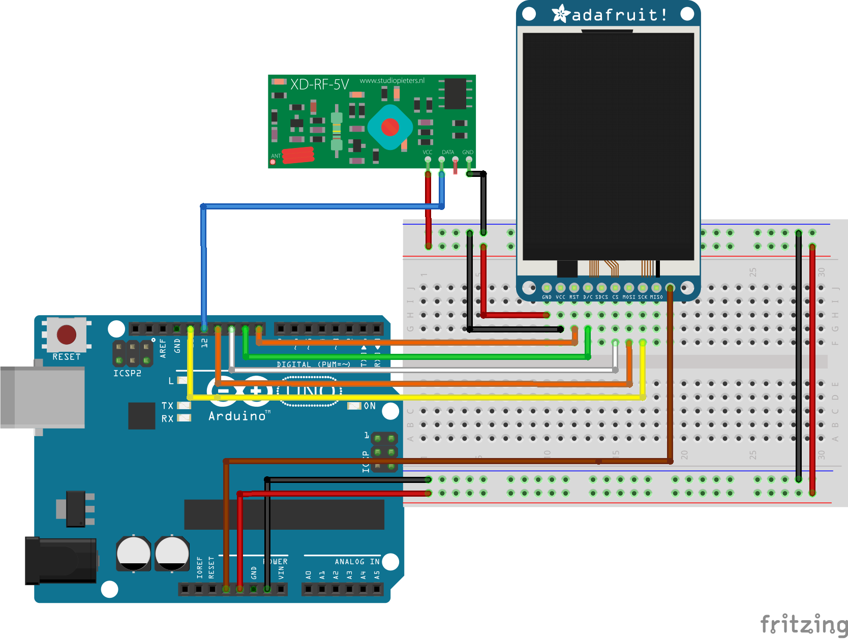
The receiver is made up of the 433 MHz RF receiver module, the ST7735 1.8″ Color TFT Display, and an Arduino Uno. Connect the components as shown below.
Schematics for Receiver
Due to a variation in pinout of the display from one manufacturer to another and for clarity, the pin connection between the Arduino and the other components that make up the receiver are mapped out below:
To better understand the use of the ST7735 1.8″ Color display with the Arduino, check out one of our previous tutorial on connecting the display to the Arduino.
With the connections all done, we can now proceed to write the code for this project.
Code
Just like we had to build two devices, we will write two different codes for this project. One of the codes is to control the transmitter and the other to control the receiver.
To easily write the code for this tutorial, we will use the libraries that make it easy to drive each part of the project. For the RF modules, we will use the virtual wire library, to send and receive data, while for the display of the received data, we will use the Adafruit GFX and the Adafruit ST7735 libraries to easily update the ST7735 LCD display. To cap it, we will use the Adafruit DHT sensor library to easily obtain temperature and humidity data from the DHT22 sensor.
The algorithm behind the code is simple. For the transmitter, obtain the temperature and humidity values from the DHT22 and send via the RF transmitter to the receiver. For the receiver, obtain the temperature and humidity value sent by the transmitter using the RF Receiver module and display on the LCD.
As usual, I will do a brief explanation of the code for the two halves of the project starting with that of the transmitter.
Transmitter code
We start by including the libraries that will be used within the code.
//Written by Nick Koumaris
//info@educ8s.tv

#include <VirtualWire.h>
#include "DHT.h"
After this, we declare the pin of the Arduino to which our DHT is connected and also specify the type of DHT being used.
#define DHTPIN 4

#define DHTTYPE DHT22
Next, we indicate the pin of the Arduino which will be used as our data transmission pin (which is connected to the data pin of the RF transmitter module) and create a struct package which will be used for sending the data.
const int led_pin = 13;
const int transmit_pin = 12;

struct package
{
  float temperature ;
  float humidity ;
};
Next, we define the type for the package and create an instance of the DHT class to address the DHT sensor.
With this done, we move to the void setup() function where we set the TX pin and other parameters to initialize the RF module.
void setup()
{
// Initialise the IO and ISR
vw_set_tx_pin(transmit_pin);
vw_set_ptt_inverted(true); // Required for DR3100
vw_setup(500); // Bits per sec
pinMode(led_pin, OUTPUT);
}
Up next is the void loop() function where we obtain the temperature and humidity using the read sensor function. After obtaining the data, it is sent using the vw_send() function. A 2000ms delay time is implemented to create an interval between the data and ensure one is sent before the other.
void loop()
{
digitalWrite(led_pin, HIGH); // Flash a light to show transmitting
readSensor();
vw_send((uint8_t *)&data, sizeof(data));
vw_wait_tx(); // Wait until the whole message is gone
digitalWrite(led_pin, LOW);
delay(2000);
}
The complete code is written below and attached to the zip file under the download section.
#include <VirtualWire.h>
#include "DHT.h"
#define DHTPIN 4
#define DHTTYPE DHT22
const int led_pin = 13;
const int transmit_pin = 12;
struct package
{
float temperature ;
float humidity ;
};
typedef struct package Package;
Package data;

DHT dht(DHTPIN, DHTTYPE);
void setup()
{
    // Initialise the IO and ISR
    vw_set_tx_pin(transmit_pin);
    vw_set_ptt_inverted(true); // Required for DR3100
    vw_setup(500);       // Bits per sec
    pinMode(led_pin, OUTPUT);
}
void loop()
{
  digitalWrite(led_pin, HIGH); // Flash a light to show transmitting
  readSensor();
  vw_send((uint8_t *)&data, sizeof(data));
  vw_wait_tx(); // Wait until the whole message is gone
  digitalWrite(led_pin, LOW);
  delay(2000);
}
void readSensor()
{
dht.begin();
delay(1000);
data.humidity = dht.readHumidity();
data.temperature = dht.readTemperature();
}
Receiver Code
As usual, we start by including the libraries that will be used.
//Written by Nick Koumaris
//info@educ8s.tv

#include <VirtualWire.h>
#include <Adafruit_ST7735.h>
#include <Adafruit_GFX.h>
Next, we declare the pins of the Arduino to which the pins of the LCD are connected.
#define TFT_CS     10
#define TFT_RST    8
#define TFT_DC     9
Adafruit_ST7735 tft = Adafruit_ST7735(TFT_CS,  TFT_DC, TFT_RST);

// Option 2: use any pins but a little slower
#define TFT_SCLK 13   // set these to be whatever pins you like!
#define TFT_MOSI 11   // set these to be whatever pins you like!
Next, we declare the pin(receive_pin) of the Arduino to which the data pin of the RF receiver module is connected and create char variables to hold the temperature and humidity values.
const int receive_pin = 12;
char temperatureChar[10];
char humidityChar[10];
Next, we create a struct package similar to the one within the transmitter code.
With this done, we move to the void setup() function where we initialize the display and the RF receiver module setting the bit rate and starting the receiver PLL.
void setup()
{
tft.initR(INITR_BLACKTAB);
tft.fillScreen(ST7735_BLACK);
printUI();
delay(1000);
// Initialise the IO and ISR
vw_set_rx_pin(receive_pin);
vw_setup(500); // Bits per sec
vw_rx_start(); // Start the receiver PLL running
}
Next, the void loop() function. We start the function by checking if a message has been received using the vw_have_message() function. If a message was received, we extract the temperature and humidity data from it and display it on the LCD.
void loop()
{
uint8_t buf[sizeof(data)];
uint8_t buflen = sizeof(data);
if (vw_have_message()) // Is there a packet for us?
{
vw_get_message(buf, &buflen);
memcpy(&data,&buf,buflen);
Serial.print("\nPackage:");
Serial.print(data.temperature);
String temperatureString = String(data.temperature,1);
temperatureString.toCharArray(temperatureChar,10);
tft.fillRect(10,20,80,30,ST7735_BLACK);
printText(temperatureChar, ST7735_WHITE,10,20,3);
String humidityString = String(data.humidity,1);
humidityString.toCharArray(humidityChar,10);
tft.fillRect(10,95,80,100,ST7735_BLACK);
printText(humidityChar, ST7735_WHITE,10,95,3);
Serial.print("\n");
Serial.println(data.humidity);
}
}
The code also includes functions which were used to display the results in a more user-friendly way.
void printText(char *text, uint16_t color, int x, int y,int textSize)
{
tft.setCursor(x, y);
tft.setTextColor(color);
tft.setTextSize(textSize);
tft.setTextWrap(true);
tft.print(text);
}
void printUI()
{
printText("TEMPERATURE", ST7735_GREEN,30,5,1); // Temperature Static Text
printText("o", ST7735_WHITE,90,13,2);
printText("C", ST7735_WHITE,105,20,3);
printText("HUMIDITY", ST7735_BLUE,30,80,1); // Temperature Static Text
printText("%", ST7735_WHITE,90,95,3);
}
The complete code for the receiver is available below. It is also attached in the zip file under the download section of this tutorial.
#include <VirtualWire.h>
#include <Adafruit_ST7735.h>
#include <Adafruit_GFX.h>
#define TFT_CS 10
#define TFT_RST 8
#define TFT_DC 9
Adafruit_ST7735 tft = Adafruit_ST7735(TFT_CS, TFT_DC, TFT_RST);
// Option 2: use any pins but a little slower!
#define TFT_SCLK 13 // set these to be whatever pins you like!
#define TFT_MOSI 11 // set these to be whatever pins you like!
const int receive_pin = 12;
char temperatureChar[10];
char humidityChar[10];
struct package
{
  float temperature = 0.0;
  float humidity = 0.0;
};
typedef struct package Package;
Package data;
void setup()
{
    tft.initR(INITR_BLACKTAB);
    tft.fillScreen(ST7735_BLACK);
    printUI();
    delay(1000);

    // Initialise the IO and ISR
    vw_set_rx_pin(receive_pin);
    vw_setup(500);	 // Bits per sec
    vw_rx_start();       // Start the receiver PLL running
}
void loop()
{
    uint8_t buf[sizeof(data)];
    uint8_t buflen = sizeof(data);

if (vw_have_message())  // Is there a packet for us?
  {
    vw_get_message(buf, &buflen);
    memcpy(&data,&buf,buflen);

    Serial.print("\nPackage:");
    Serial.print(data.temperature);
    String temperatureString = String(data.temperature,1);
    temperatureString.toCharArray(temperatureChar,10);
    tft.fillRect(10,20,80,30,ST7735_BLACK);
    printText(temperatureChar, ST7735_WHITE,10,20,3);

    String humidityString = String(data.humidity,1);
    humidityString.toCharArray(humidityChar,10);
    tft.fillRect(10,95,80,100,ST7735_BLACK);
    printText(humidityChar, ST7735_WHITE,10,95,3);

    Serial.print("\n");
    Serial.println(data.humidity);
  }
}
void printText(char *text, uint16_t color, int x, int y,int textSize)
{
  tft.setCursor(x, y);
  tft.setTextColor(color);
  tft.setTextSize(textSize);
  tft.setTextWrap(true);
  tft.print(text);
}

void printUI()
{
    printText("TEMPERATURE", ST7735_GREEN,30,5,1);  // Temperature Static Text
    printText("o", ST7735_WHITE,90,13,2);
    printText("C", ST7735_WHITE,105,20,3);

    printText("HUMIDITY", ST7735_BLUE,30,80,1);  // Temperature Static Text
    printText("%", ST7735_WHITE,90,95,3);
}
Demo
Upload the corresponding code to each of the Arduinos. Both Arduino boards can be powered using a battery pack. Few minutes after switching the devices on, you should see the temperature and humidity data, displayed on the LCD.
The range of the 433 MHz Transmitter and receiver module pair is generally small but by soldering external antennas, their range could be increased.
That’s it for this tutorial guys, did you make anything based on this project, or you made modifications to get better range for your modules, feel free to drop a comment.
RS Components is now stocking Microchip’s MPLAB Snap in-circuit debugger/programmer, for simple and quick debugging and programming of most Microchip PIC, AVR and SAM flash MCUs. [via]
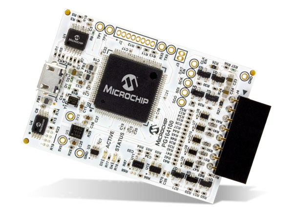
The MPLAB® Snap In-Circuit Debugger/Programmer allows affordable, fast and easy debugging and programming of most PIC®, dsPIC® and AVR flash MCUs, using the powerful graphical user interface of MPLAB X Integrated Development Environment (IDE) version 5.05 or later.
Connects to computer via high speed USB 2.0(480) cable An 8- pin SIL programming connector and the option to use various interfaces program devices using MPLAB X IDE or MPLAB IPE
The MCUs programmable by the MPLAB Snap include 32-bit devices and dsPIC digital signal controllers (DSCs). MPLAB Snap is ideal for projects that do not require high-voltage programming or advanced debugging. The debugger/programmer offers all the entry-level features that are required to debug prototypes quickly.
MPLAB Snap uses the GUI of the MPLAB X IDE, version 5.05 or later. It uses a 480 Mbps USB 2.0 interface to connect to the computer and an 8-pin single in-line (SIL) connector to connect to the target. Two device I/O pins and the reset line are used to implement in-circuit debugging and Microchip ICSP (in-circuit serial programming). MPLAB Snap’s onboard 32-bit 300 MHz SAM E70 MCU, based on an Arm Cortex-M7 core, matches the clocking speed of the target device.
The ESP8266 had been in the tech scene for over four years now and has seen various competitors like the RTL8710 or, more recently, the RDA5981. But none of them has really been able to knock off the ESP8266 from its throne. The ESP8266 is seen by most as being “good enough.” So the need to switch to a new chip is not necessary. Regardless this, SeeedStudio has developed a new chip, the Air602 module.
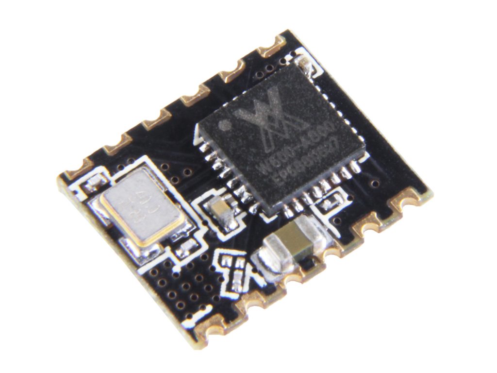
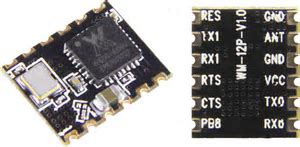
Air602 WiFi Module
Its the latest of hardware WiFi chip to hit the market. Modeled on the WinnerMicro W600, an Arm Cortex-M3 with 1MB of Flash on-chip with 2.4GHz WiFi support, the Air602 module has a tiny 10×12 mm footprint less than half the size of the ESP-01 which measures 24.8 × 14.3 mm and this is partially because the module has no onboard antenna or antenna socket.
The W600 has dual UARTs, I2C, SPI and I2S interfaces, and supports RTC and hardware cryptography. The Air602 module has limited pinouts, offering 12 pins. Two of these pins are dedicated to ground pins, one to +3.3V power, one to the antenna, and one reset pin, that leaves only seven available for I/O, which are shared between the two UARTs with SPI available as a secondary option and a single GPIO pin.
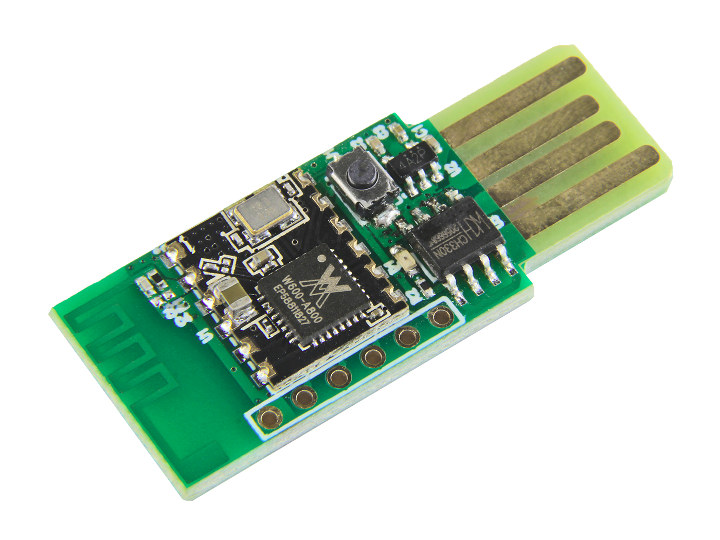
SeeedStudio is also offering an Air602-based development board if an antenna-less module is not persuasive enough for the user. The board is equipped with the missing antenna in the form of an onboard PCB antenna and USB connectivity. However, pin availability is even more limited, with one of the two UART connections taken for the USB. Only 5 pins are broken out by the board. This is still better than the ESP-01 breakout, and a lot easier to manage when it comes to the wiring. The real obstacle of the board is the development toolchain, just like in the early days of the ESP8266.
The module ships out with a LUAT firmware, which combines LUA and AT commands. Documentation is in short supply, just as the early period of the ESP8266, and mostly written in Chinese. The major advantage of the Air602 is that, unlike the ESP8266 which is based on an Xtensa core, the W600 chip at the heart of the Air602 is an ARM processor.
Air602 Development Board
You can get the Air602 module or even a development board for just $1 on the Chinese facing site. This makes the Air602 not just price competitive with the ESP8266, but also the first competitor to be cheaper than the Espressif modules. The Air602 module is also available for $1.90 per piece from SeeedStudio, and the Air602 development board, which has both integrated USB and an onboard antenna for $2.90 per piece.
Coupons are a great way to save money when purchasing something, but finding one could be somehow tricky most of the times and not all business owners offer coupons. PCB making and manufacturing can be sometimes expensive depending on your point of view and using coupons is a win-win situation. In this post, I will highlight some easy ways to secure coupons for free for reducing the cost of your printed circuit board project, and sometimes you might not even need to pay for them. Coupons will be helpful especially when you are embarking on large-scale PCB manufacturing and assembly, as those little bucks matter.
PCBWay, the Shenzhen-based manufacturing company specializes in PCB prototyping, PCB Assembly, SMD Stencil, and several others have been pushing the boundaries of the PCB Technology ever since why still impacting to the maker’s community as much as possible. PCBWay has provided an avenue for innovators, students, makers, engineers, teachers to make their printed circuit boards and still get value for their money.
Below are some ways to quickly get free coupons for your next PCB project on PCBWay:
Through the PCBWay Sponsorship Program – The PCBWay sponsorship program is available for teachers, students and anyone that is ready to opensource their next PCB project. Users can get about 10 – 15 % discount and some even going ahead getting up to $100 cash coupons which only reward 5 times in a month. For more about the PCBWay Sponsorship program, visit the sponsorship page here.
Through the Powerful Referral Program – Referral programs have been used in several online platforms to allow users to earn free money or coupons by inviting others. PCBWay referral program gifts cash and coupons to new and existing members of their platform. Users need to invite new members to use the platform through the referral link; For every new user that gets added through the referral link, you will get a $20 discount coupon after any successful payment from that member. Also, you will earn 10% of the amount they spend on their first order. More information about the referral program can be found here.
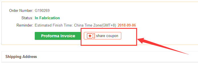
Through Shared Coupons – After a user completed an order on PCBWay, the user will see a description of sharing coupons popping on top of the page, and this popup can be shared with friends, and by successfully sharing these coupons, you stand a chance of winning some yourself.
Get Commision for Sharing Your Project to the World – If you are ready to share your PCB project to the community, you can get a potential 10% commission or discount for the total PCB cost. Learn more here.
Share your experience – After using PCBWay, you can get some pretty coupon deals by just telling the world about your experience. Make a review video on Youtube/Instagram/Facebook or any other social media platform of your choice and stand a chance to win about $20 to $100 cash coupon that can be claimed in your next order. If you can make your video reach up to 500 views, you will get a full 100% discount on your order. Learn more here.
Get involved in PCB design contest – PCBWay organizes design contest periodically, and you can participate to win some fantastic prices there. The 2nd edition of the PCBWay design contest is on, and you can find out more on the competition page.
PCBWay is always looking for ways to make its customer happier every day and most importantly grow the maker’s community by offering special deals, coupons, competition, and others. You can find out about several potential coupons, prices and deals from the PCBWay Free PCB page here.
USBNinja is an information security and penetration testing tool that looks and functions just like a regular USB cable (both power and data) until a wireless remote control triggers it to deliver your choice of attack payload to the host machine. In essence, USBNinja is the next step in the evolution of BadUSB, embedding the attack in the USB cable itself.
The Attack
When plugged into a host computer, USBNinja acts just like a regular USB cable. For example, it can be used both to charge your phone and to transfer images from your phone to your computer. However, perfectly concealed within USBNinja is a very small Bluetooth device, patiently waiting. When USBNinja receives the secret command, either from a smartphone running the USBNinja app or from our custom-built Bluetooth remote control, it goes from a passive cable to a stealthy attacker by emulating a USB mouse and/or keyboard to deliver its hidden payload to the host computer.
The Payload
The payload delivered by USBNinja is completely customizable. You can use the standard Arduino IDE to create your own payload and we’ll also provide plenty of examples of payloads that inject keystrokes and move and click the mouse.
Use Cases
USBNinja is truly a versatile tool, with applications such as practical jokes, magic tricks, secret love confessions, game assists, and information security trainings. We leave it as an exercise to the reader to come up with their own uses.
Features & Specifications
Cable Physical Characteristics
Length: 1 m
Color: white
Connector options: Micro-USB, USB Type-C, Lightning
Voltage range: 4-25 V (supports fast charging)
Current consumption: 10 mA (typical)
Full-rate USB data transmission
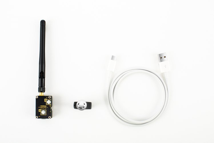
Remote Control
High-powered Bluetooth wireless (customizable name and password)
Battery: 3.6 V, 40 mAh, rechargeable
Standby current: 80 μA
Transmission current: 30 mA
Range (under ideal conditions with antenna):
30 m with 2 dBi, 3 cm antenna
50 m with 3 dBi, 11 cm antenna
100 m with 18 dBi directional panel antenna
Mobile App
Alternative to remote control for triggering payload
Open source and freely available
Programming
Payload programmable with standard Arduino IDE (Windows/Mac/Linux/Android)
Access bootloader with non-contact magnetic ring
Source code provided for example payload
The project is live on CrowdSupply and has 24 days to go. Pledges start from 79 USD.
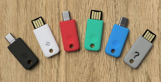
Two security keys for logging in safely online. Protect yourself from phishing and other attacks across Google, Facebook, and more.
We’re incredibly excited to announce Solo, the world’s first open source security key that supports the newest FIDO2 standard for secure login!
Secure login is for people who want to be protected against phishing, account takeover, and other online attacks – basically for anyone who uses Google, Facebook, Dropbox, Twitter, Github… Let us guess: you’re one of these people? Great, then Solo is for you, and will help you stay protected!
In making Solo, our biggest dilemma has been “how can we make secure login more personable and accessible to everyone?” The answer was astonishingly easy: colors! (Though we’re still wondering why you can’t choose your color when you buy other security keys.) We’re going to add colored silicone cases to Solo, starting with black & white cases, and with your support we want to unlock more and more colors. Check back often for updates, and help us reach our stretch goals.
Solo is on Kickstarter until October 28th, and has already exceeded its goal many times over. One USB-only Solo costs $14, and the NFC-enabled Solo Tap costs $29. Solo rewards are expected to ship in December, and Solo Tap rewards ship in February.
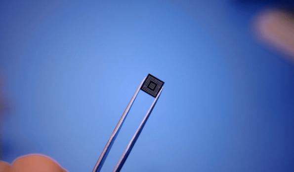
Startup Gyrfalcon introduced the Laceli AI Compute Stick, based on the same ASIC, early in 2018 to compete with the Neural Compute Stick introduced by Intel in 2017 . [via]
The Lightspeeur 2801S is the first instantiation of Gyrfalcon’s APiM processing-in-memory architecture. The use of memory as a processing element can be used to minimize the data movement that is a large part of the power consumption of conventional processors. The chip has roughly 28,000 parallel computing cores and does not require external memory for AI inference.
The Lightspeeur 2801S achieves 2.8 tera operations per second (TOPS) while consuming 300mW yielding 9.3TOPS/W in a package measuring 7mm by 7mm by 2.8mm. For heavier loads the ASIC be set in arrays from 2 to 32 chips per board.
Balancing the cost-performance-energy equation has been a challenge for developers looking to bring AI-enabled equipment to market at scale,” said Lin Yang, chief scientist at Gyrfalcon, in a statement. “By deploying APiM and MPE on a standard, commoditized ASIC, GTI is enabling our customers to bring innovative, AI-enabled devices to the masses.
Gyrfalcon was founded in 2017 by a group of entrepreneurs and engineers that came from such companies as AMD, Spansion, TDK, Legend Silicon, Omnivision, Cadence, C-Cube and C2 Microsystems.
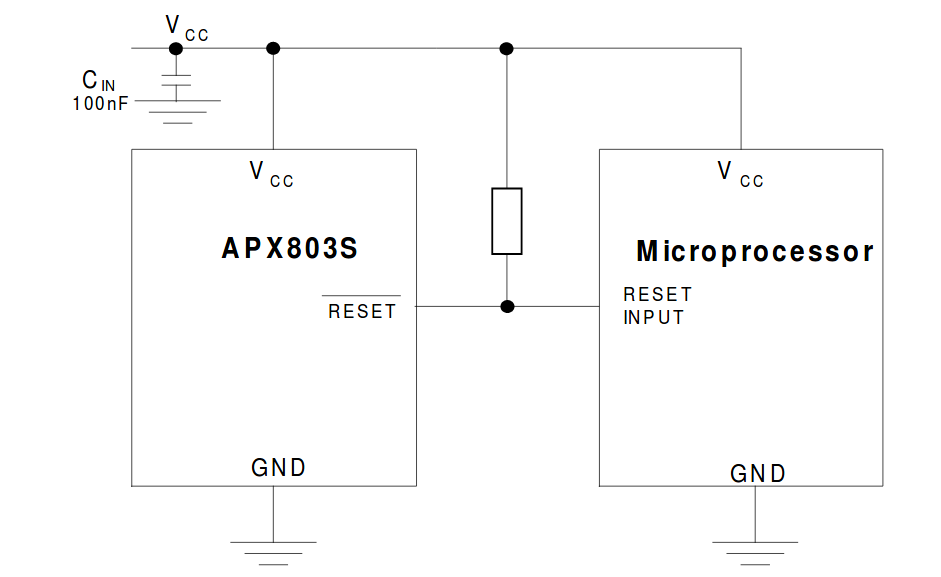
Vdd brownouts are among the most common antipodes of microcontroller design – they are especially annoying, as their presence is not easy to detect. Diodes Incorporated provides a new family of easy-to-use supply voltage monitor ICs.
From a principal point of view, the parts are not difficult to understand. Simply connect them to VCC and ground, thereby allowing the chip to keep an eye on the supply. After that, a pull-up resistor is needed to provide current to the open drain active-low reset output which resets the microprocessor.
The addition of the resistor shown in figure one is intentional – some (odd or high-end) microcontrollers can also assert the reset line on their own.
…handling brownouts requires but one chip and a resistor