Nuand’s Launches the BladeRF 2.0 Micro With FPGA Support

Everyone believes the future is going to be bright and a lot are betting that smart devices of the future will have the ability to self-adapt to its environment and that’s why some are backing on Cognitive Radios which are Software Defined Radios with AI. Our world is becoming crowded with several smart devices, and the explosion of IoT has made the demand and durability of robust radio networks high while still being security conscious, SDRs (Software-Defined Radios) is believed will make this a possibility.

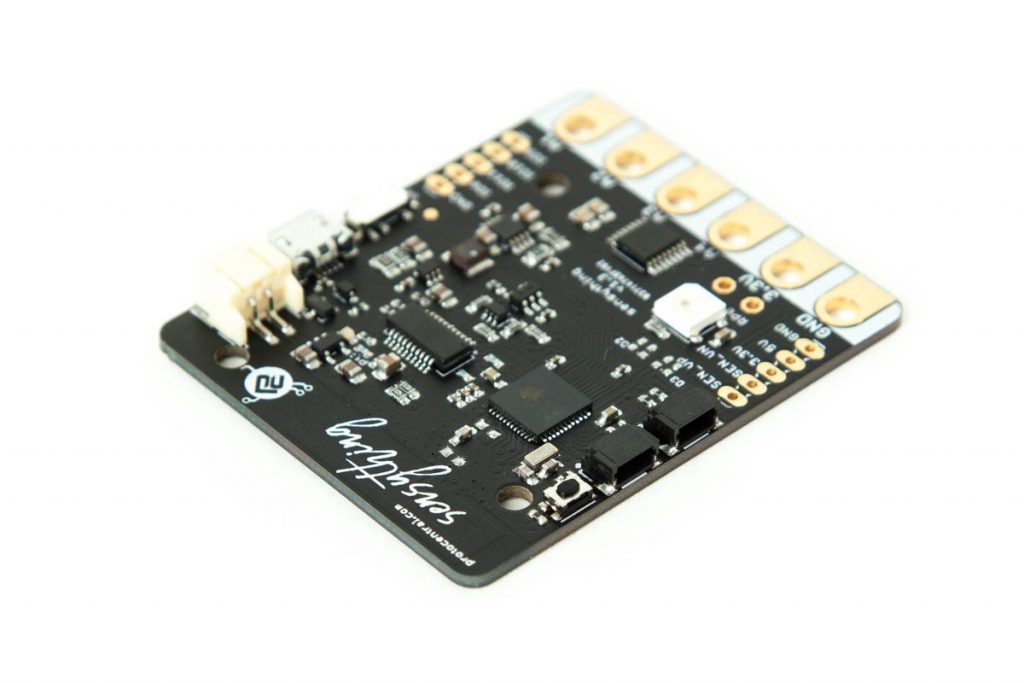
Software Defined Radios are radios that enable one to change the transmitting or receiving radio frequency in software alone. Five years ago, the first bladeRF software-defined radio module was released in San Francisco. BladeRF was created by Nuand to help teachers, students, researchers, and even hobbyists learn while experimenting with Radio Frequency communication. The Nuand team has recently launched a new bladeRF SDR module which is called bladeRF 2.0, and it comes in two versions.

The first module is called BladeRF 2.0 micro xA4, while the other module is called the BladeRF 2.0 micro xA9. The bladeRF 2.0 micro is compatible with several third-party software like the GNU Radio, GQRX, SDR-Radio, gr-fosphor, SoapySDR, and others. They are expected to easy work comfortably with Windows, Linux and Mac Operating Systems.

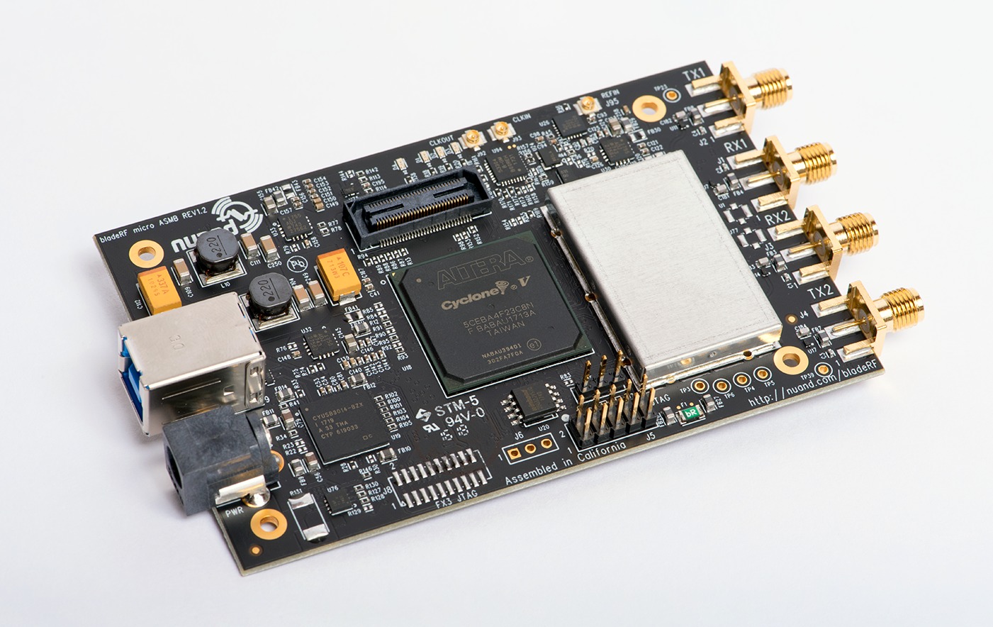
The modules are very similar; however, the only major difference is that the latter comes with the Intel’s 301 KLE Cyclone V FPGA (Field Programmable Gate Array). The former, however, comes with the 49KLE Cyclone V FPGA. The FPGA which provides the interface between the FX3 and Analog Devices AD9361 RF transceiver has single-cycle access embedded memory, which is fully programmable. Other similar features between both modules are listed below:

SIMILAR FEATURES OF BLADERF 2.0 MICRO XA4 AND BLADERF 2.0 MICRO XA9

  • 47 MHz to 6 GHz frequency range
  • 44 MHz sampling rate
  • 56 MHz filtered bandwidth (IBW)
  • Dimensions: 6.3cm by 10.2cm by 1.8cm
  • Weight: 90 grams
  • Operating temperature: 0°C to 70°C
  • 128-tap digital FIR filtering
  • Has USB 3.0 support
  • 32-pin I/O header
  • 2×2 MIMO channels


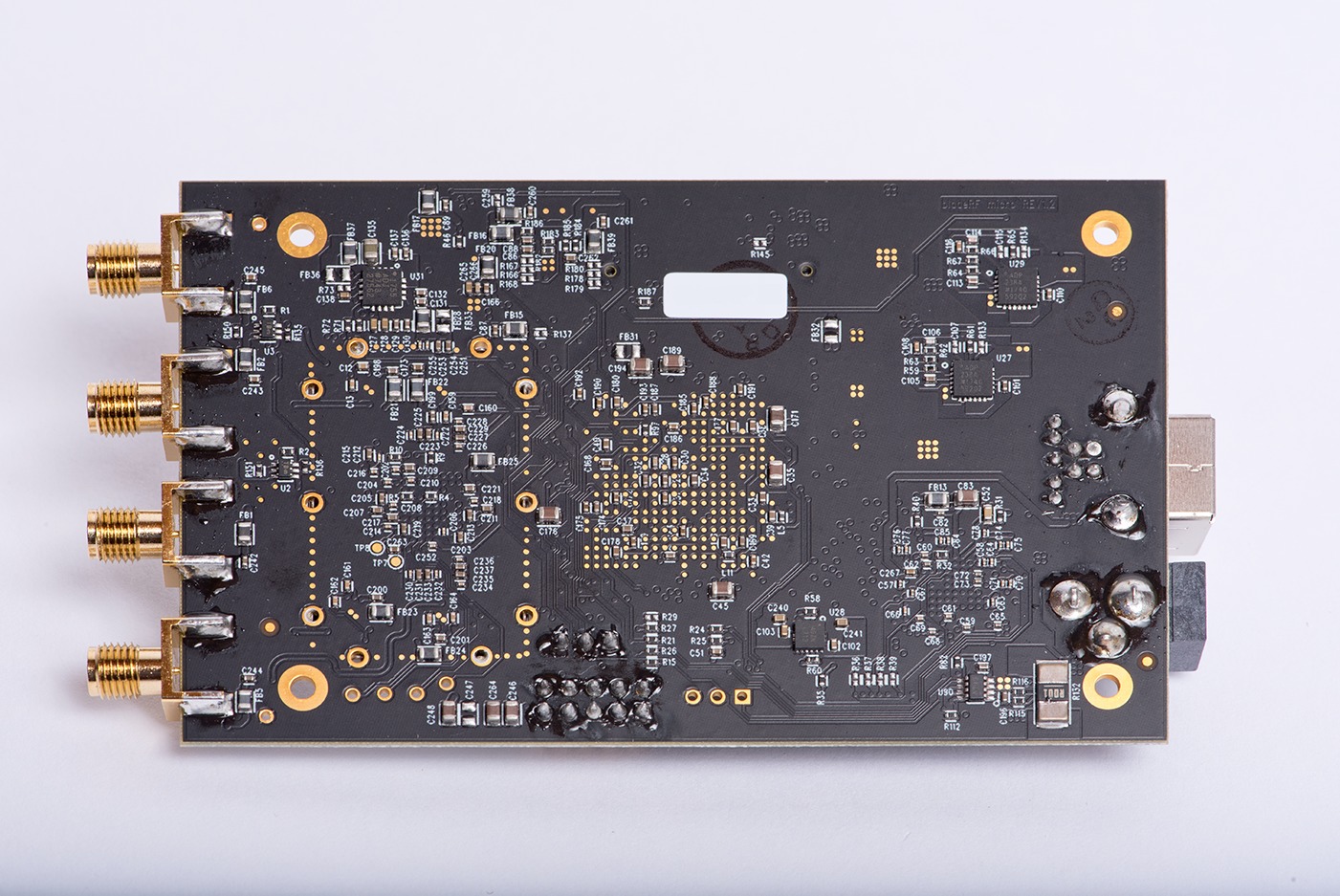
The bladeRF comes at a punching price though; the micro xA4 costs $480 and it is available online for purchase here while the micro xA9 is being sold for a steeper $720 and also available for purchase as well. Due to the larger amount of logic gates found on the FPGA, the micro xA9 can do more signal processing without intervention or any sort of help. The RF shield cap protects the sensitive RF components from Electromagnetic Interference (EMI) which means the bladeRF 2.0 micro can operate effectively in challenging environments.

The bladeRF 2.0 micro modules were not the only things released, and they came with additional equipment as listed below.

  • A clear Polycarbonate case for the bladeRF 2.0 micro – $20
  • Bias-tee powered Power Amplifier (TX) for the bladeRF 2.0 micro – $30
  • Wideband and general purpose Tri-band Antenna – $25
  • Bias-tee powered Low Noise Amplifier (RX) for the bladeRF 2.0 micro – $30

Software radio is gradually becoming an emerging technology for flexible radio systems and combined with the likes of Artificial Intelligence, and we might just be able to create a future-proof communication system that will easily see applications in several industries ranging from agriculture to security industry.

Clientron Releases its First ARM Based Thin Client

Clientron Corporation, a dedicated provider of intelligent solutions that offers high quality and high performance computing platforms including Thin Client, POS and intelligent systems has officially released its  first ARM- based Clientron thin client specifically designed for high performance and economic desktop virtualization solution for the education, SMB, finance, healthcare and enterprise market. The thin client dubbed the S-Cube Pi 3 B+ -the smallest and most power efficient model yet, running on less than 5 watts- is the first thin client that runs on the latest Raspberry Pi 3 B+ SBC and supports various Virtualization software providers like Microsoft RDP, Citrix XenDesktop and VMware Horizon view with secure Linux operating system.

Compared with other Raspberry Pi 3 Model thin clients from ViewSonic, ClearCube, NComputing, the Clientron thin client is powered by a faster ARM Cortex-A53 quad-core 1.4GHz Broadcom 64-bit processor, it smoothly runs highly demanding functions including Bluetooth 4.2 and Wi-Fi wireless connection, optional PoE (Power over Ethernet), 1Gb LAN, one HDMI display output, an internal micro SD card expansion and comes in an ultra-compact credit card size form factor of 91.7 x 67 x 29.2mm- which is actually not a cube as the name suggests- with other enhancements.

The S-Cube Pi 3 B+ also comes in a fanless and noise free design with 10/100/1000 Ethernet port with Wifi speeds up 300Mbps and 1GB LPDDR2 RAM, 4 USB 2.0 host ports, an audio jack, and a micro-USB port for power. Its HDMI port support up to 1920 x 1200 pixels resolution. In addition to these basic Raspberry Pi features, it supports a Kensington security lock connector and an optional VESA (Video Electronics Standards Association- A technical standard for Computer display) metal mounting kit and supports temperature ranges from 0 to 35oC degress.

The Clientron S-Cube Raspberry Pi 3 B+ comes with power efficient and cost-effective benefits, it offers the lowest endpoints acquisition cost of desktop virtualization solution for customers. Because of its PC- like working experience and capability to run virtual sessions from various workspace environments, it is suitable to enhance working environments in different markets.

Apart from running thin client solutions, the S-Cube Pi 3 B+ can be used for various applications such as digital signage and smart retail applications.

Clientron has also recently released other models based on the intel Braswell Q800 and R800 processor which runs Windows Embedded Standard 7, Win10 IoT Enterprise with Linux available per request.

The Clientron S-Cube Raspberry Pi 3 B+ is now available. More information can be found in Clientron S-Cube Raspberry Pi 3 B+ product and announcement page.

RUEF300 – A fuse which never blows

Surface-mount fuses do a good job at protecting components from burning up – sadly, exchanging them is not a simple task manageable by end users. LittelFuse‘s RUEF series provide an attractive alternative, which is not widely known.

Parts like the RUEF300 are based on the concept of the PTC. Designers switch them in series with the load, meaning that the parts normally have a pretty low resistance (less than 1 Ohm). Current flows through them, their substrate temperature increases by the well-known thermal effect.

While the normal PTC changes its value linearly or exponentially, the resettable fuse jumps when reaching a specific temperature. At this point, the resistance increases dramatically, thereby dissipating most – but not all (!!!) – current through the load. When the overload situation ceases, the substrate cools off and restores normal current flow.

This makes PTC resettable fuses ideally suited for all cases where stupidity can cause transient shorts. A classic example would be a USB port – users tend to plug in things which they should not. Protecting the hub with a PTC is the best course of action: once the offending peripheral is removed, normal operation resumes without customer service action.

Beware of the consequences

The large thermal capacitance of the part leads to a relatively slow switching process – while a normal fuse can switch out in less than a second, the part on hand can take up to 10 seconds in a worst-case scenario. Our figure shows the problem: as the ambient temperature changes, the jump point changes too – in some cases, the tripping current can half itself.

A practical example

Now that we got the classic principle of function sorted, let us look at a practical example. The RUEF300 mentioned in the introduction can handle 30V DC or AC and is guaranteed to survive to either 100A DC or 70A RMS.

Switching takes place at a trip current of 6A, with the hold current level being set at 3A. In clear words, 3A can flow through the part forever. A current of 6A causes the part to trip eventually. The emphasis is on eventually: When loaded with 15 Amps, LittelFuse promises that the switching will take less than 10.8 seconds – not a fast part by any means.

source: www.oemsecrets.com

Intel releases seven NUCs with Coffee Lake and 10nm Canyon Lake CPUs

Despite struggles and delays with its 10nm processor, Intel has finally released five NUCs (Next Unit of Computing) mini-PC kits that comes with 14nm, 8th Generation Coffee Lake CPU. It also released two NUCs that comes with its 10nm Cannon Lake chips and comes configured with Windows 10 with shipments to begin in October or November. The coffee lake NUC supports any Intel-ready OS including Linux and Windows and they come in barebones kits with RAM and Storage. The windows 10 Home powered crimson Canyon lake NUCs are among the first products that comes with a dual-core, 15W TDP core i3-8121U coffee lake CPU aside from a new version of a Lenovo IdeaPad 330 laptop.

Intel’s Bean Canyon NUC

The five new Coffee lake powered Bean Canyon NUCs comes with H-, M- and T- series Intel core chips and share many of the features as the Baby Canyon NUCs released earlier in April. They also have CPUs with 28W TDPs and supports up to 32GB dual channel DDR4-2400 RAM. They feature Intel’s fastest graphic chip- compared to the desktop models- known as the Iris Plus 655 graphics with 128MB eDRAM. The increased eDRAM stands out from previous parts that just supports 64MB eDRAM cache which delivers better graphic performance and can be used as general cache. The various options available for the five NUCs are:

  • NUC8i7BEH (Core i7-8559U)
  • NUC8i5BEH (Core i5-8259U)
  • NUC8i5BEK (Core i5-8259U)
  • NUC8i3BEH (Core i3-8109U)
  • NUC8i3BEK (Core i3-8109U)

The Bean canyon NUCs comes with an HDMI 2.0a host port with resolution up to 4096 x 2304 and 7.1 surround sound audio. There’s also a Thunderbolt 3 port which supports USB 3.1 Gen 2 (with speed up to 10Gbps) and can be used as a DisplayPort 1.2 connection. It also includes four USB 3.1 host ports (one of the ports supports charging) and two USB 2.0 headers.

The Bean Canyon NUCs are also equipped with Bluetooth 5.0, Intel Wireless AC 9560, dual GbE ports, a 12-19VDC input, power button, a MicroSD slot, 3.6mm audio jack and a support for Kensington lock.

The Crimson Canyon NUCs with Cannon lake chips no doubt gives us a glimpse of future Intel 10nm generation of chips. These game oriented NUCs comes in two models- Crimson Canyon NUC8i3CYSM (has 8GB of LPDDR4-2400) and NUC8i3CYSN (has 4GB of LPDDR4-2400) and it is built with windows 10 Home and like another windows PC, it can be swapped with Linux.

Intel’s NUC crimson canyon

The Crimson Canyon NUCs powered by Intel Cannon lake chips is accompanied by AMD’s discrete Radeon 540 GPUs with Integrated 2GB of GDDR5 Memory which makes it different from the Bear Canyon NUCs’ integrated Iris graphics.

Both Crimson Canyon Models are very similar to the Bean Canyon NUCs with the only evident difference is the addition of a second HDMI 2.0 port instead of a USB Type-C DisplayPort.

These intel NUCs are good options for casual users and the high graphics performance can allow to stream and play eSports games and users should be ready to spend extra cash on storage and memory as these NUCs are just Barebone kits.

Meanwhile they are reports have leaked about a new 14nm 9th Gen core chip family which Intelis expected to release in October.

Check Intel’s NUCs kit page for full spec

Keysight Keysight UXR 110GHz BW, 256GS/s, 10-bit, 4-Channel Real-Time Oscilloscope Teardown & Experiments

In this episode Shahriar takes a look at one of the most advanced electrical test and measurement instruments ever created. The Keysight UXR-Series Real-Time Oscilloscope brings 110GHz of analog bandwidth and 256GS/s real-time sampling at 4-channels simultaneously. To make it even more impressive, the entire data-conversion architecture is in 10-bits. This implies that the instruments captures, processes, stores and displays over 10Tb/s of information.

Various architectures of state-of-the art oscilloscopes from Keysight, LeCroy and Tektronix are examined and compared against the new real-time architecture of the UXR-Series oscilloscope. The teardown of the front-end 110GHz module along with the data acquisition board is presented and analyzed in detail. The instrument showcases a wide range of Keysight technologies implemented in various technologies such as InP, SiGe BiCMOS, 65nm CMOS and 28nm CMOS nodes. In combination with Hyper-Cube memory module, data can be captured at 256GS/S from all 4-channels at the same time. Several variants of the UXR-Series oscilloscope will be available from 13GHz to 110GHz bandwidths.

Keysight Keysight UXR 110GHz BW, 256GS/s, 10-bit, 4-Channel Real-Time Oscilloscope Teardown & Experiments – [Link]

ArdOsc – Arduino Oscilloscope in a Matchbox

Peter Balch @ instructables.com build an Arduino based tiny oscilloscope and a detailed explanation is given on the tutorial. He writes:

Why would I want a tiny oscillscope? I’ve got a room full of electronic Stuff including four oscillscopes. But it’s a fuss using them. It would be nice to have something that fits in my pocket, that sits next to the circuit I’m working on and that’s as easy to use as a multimeter.

This oscilloscope costs the price of an Arduino Nano (£2 and a display (£3) plus a few pence for resistors, etc. It’s specification is:

ArdOsc – Arduino Oscilloscope in a Matchbox – [Link]

Sensything Provides Sensors, Processing, and Wireless on a Single Board

Multi-sensor data acquisition, processing, and Wi-Fi/Bluetooth communication in a single, open source board. Sense anything.

Sensything is an open source, high-resolution (24-bit), Wi-Fi and Bluetooth-enabled sensor interface platform that supports multiple sensor readings. In most cases, it offers a single-board, single-platform solution for acquiring and logging multiple sensor readings that can be seen/sent through an Android app, an IoT or analytics platform, or over an ordinary USB connection.

Sensything is based on the popular ESP32 SoC for IoT applications and includes the ADS1220 24-bit ADC that provides low-noise data acquisition. It provides all the accompanying components, including a Li-ion battery and an on-board,low-noise, five volt power source for reliable low-noise performance. Additionally, extra GPIO pins and support for Sparkfun’s Qwiic connector standard makes multi-modal sensor data fusion and recording easy.

The project is live on Crowdsupply and has 36 days to go.

DIY NAS / Router in 3-bay hot swap enclosure

A 2-bay, low power, ARM-based NAS and router. The project repository is here.

The enclosure is an Athena Power BP-SAC2131B 3.5” HDD Hot-Swap Backplane Module. This is a a 3-bay hot swap backplane intended to go into two 5.25” bays of a server. This is not a trayless backplane, the hard disks must be mounted using four included screws.

This is a 3-bay case, but I only need the top two bays for hard drives. In the bottom bay I will put the computer that runs the NAS. Something like a Pico-ITX or 3.5” SBC computer will fit within the footprint of a hard dive.

The main problem with using an internal enclosure as a case is that all the SATA connections ago out the back of the case, not internal for connections to a computer.

Luckily there is a slot on the back of the case. Using something like these very thin blue SATA cables, I can connect an internal computer to the back of the case

  • Cost less than a cheap commercial 2-bay NAS (~$200)
  • Low power
  • NAS for local file sharing
  • A limited router to segregate scary “smart” devices on the LAN
  • Maybe run some IoT things

DIY NAS / Router in 3-bay hot swap enclosure – [Link]

Easy Motion and Gesture Detection by PIR Sensor & Arduino

Here we use PIR sensor and Arduino to detect the motion of a hand. This detection can be used to operate electronic equipment. By ElectroPeak @ hackster.io:

In this article, we’ll show you how to make a gesture detector by simple components like PIR sensor and Arduino Nano. At the end of this article you can:

  • Explain PIR sensor applications and how it works
  • Run an 8-Pixel PIR sensor named TPA81
  • Use PIR sensor to detect motion and gesture by Arduino
  • Make a cool detector to increase or decrease your speaker volume

Easy Motion and Gesture Detection by PIR Sensor & Arduino – [Link]

Programming Atmega328p Microcontroller with Arduino IDE

Introduction

Over the past few tutorials, we have mentioned several scenarios where using any of the Arduino board in a project may be an overkill due to the cost, size, and more technical reasons such as high power consumption. In the last tutorial, we discussed an alternative way of using Arduino, i.e. using the Atmega328p microcontroller alone which removes all the downsides of using the Arduino board, while retaining one of the biggest benefits of the Arduino platform; the ease of programming.

Atmega328p Microcontroller

We covered details on preparing the Atmega328p microcontroller for programming by flashing the Arduino bootloader on Atmega328p and today’s tutorial will be a follow up to that tutorial, as we will look at how to program the boot-loaded Atmega328p microcontroller using the Arduino IDE.

The Atmega328p microcontroller, like any other microcontroller, can be quite tasking to use for a beginner. They usually require a certain set of tools, including a programmer (hardware), and a development platform (e.g Atmel Studio) for writing code. These development platforms, unlike the Arduino IDE usually require high knowledge of C or other programming languages, without the shortcuts and simplified functions which the Arduino provides.

To remove this difficulty, the microcontroller is flashed with the Arduino bootloader, which makes it ready for programming using the simpler and easy to use Arduino IDE.

To program the microcontroller using the Arduino IDE, the microcontroller must be connected via some sort of hardware to the computer. This is usually done via two major ways:

  1. Using a USB to Serial/TTL Adapter
  2. Using an Arduino board

Each of these approaches provides the microcontroller with an interface that enables interaction between the computer and the microcontroller.

We will take each of these approaches one after the other and look at the components and setup required to upload code to the microcontroller.

Using a USB to Serial/TTL Adapter

USB to Serial/TTL Adapter

The first approach involves the connection of a USB to serial adapter to the microcontroller. The USB to Serial/TTL adapter converts data signals from the USB on the computer to serial/TTL for the microcontroller and vice versa. This enables communication from the microcontroller (serial) with the Arduino IDE running on the PC (USB). This setup, compared to the second one, is by far the cheapest, as these adapters are usually very cheap.

Required Components

The following components are required for this approach;

  1. Atmega328P microcontroller with the Arduino Bootloader installed
  2. Breadboard
  3. USB to serial/TTL Adapter
  4. 16MHz crystal oscillator
  5. 22pf capacitors  x2
  6. 100nf capacitor
  7. Jumper Wires
  8. 100 ohms resistor
  9. LED

Schematic

Connect USB to Serial/TTL adapter to the microcontroller as shown in the schematics below. Don’t forget that this procedure will only work if the microcontroller has been flashed with a bootloader according to the procedure described in the last tutorial.

Schematics 1: USB to Serial Adapter and the Atmega328P

Most adapters can be configured to work at either 5v or 3.3v logic level. Ensure yours is configured to work on the 5v voltage level since supply to the microcontroller is 5v.

Uploading Code

Uploading code to the microcontroller after you are done with the connections, require no additional work asides, what you would have done if you where using an Arduino board. After typing in your code, select the port to which your adapter is connected, followed by the board type and hit the upload button. Upload takes only a few seconds, same as the Arduino board.

Note: when programming the Atmega328p MCU using the Arduino IDE, the matching board type you have to select is the “Arduino Duemilanove or Nano w/ ATmega328” board.

To test the setup, we will use the Arduino blink example. Select the example and click upload. You should see the connected LED start blinking after a while.


Using an Arduino Board

The second approach involves the use of an Arduino board in either of two similar ways;

  1. By replacing the microcontroller on the Arduino Uno with the one to be programmed
  2. By using any of the Arduino boards as an In-system programmer.

The first mode is the easiest way to upload code to the microcontroller, as it involves just replacing the microcontroller on the Uno, with the one to be programmed. However, this may not be the best when prototyping as the move of the chip from the Arduino to the project, back and forth, could lead to the pins of the microcontroller being damaged. Another downside to this is that it only works with the Arduino Uno as all other Arduino boards, use SMD type of microcontrollers which makes replacement impractical and development, expensive.

So no schematic for this, just swap the microcontroller and hit upload.

The second method involves the use of the Arduino Uno as an In-system programmer.

Required components

To use this approach, you will need the following components;

  1. Arduino Uno
  2. Breadboard
  3. USB to serial/TTL Adapter
  4. 16MHz crystal oscillator
  5. 22pf capacitors  x2
  6. Jumper Wires
  7. 10k resistor
  8. 100 ohms resistor
  9. LED

Schematics

Connect the components as shown in the schematics below.

Programming Atmeg328p with the Arduino Uno

While using this approach, it is important to remove the microcontroller of the Arduino board to prevent interference.

Upload Code

Code upload process is the same as already described. Type the code to be uploaded or select an example -> select the board type (Duemilanove or Nano W/atmeg328), select the correct port and click upload. The code will be uploaded to the microcontroller.

After successful code upload using any of the approaches described above, the Arduino or USB – Serial/TTL converter can be disconnected and the project connected to a battery to run on standalone as shown in the image below.

Programmed Atmega328p Microcontroller

That’s it for this tutorial guys, thanks for following.

Feel free to drop questions and comments under the comment section, I will do my best to respond to them asap.

Till next time!

TOP PCB Companies