Smartphone’s camera detects your face and the fan moves automatically according to your face. This is an easy project using obniz, servo motor, smartphone, and a fan.
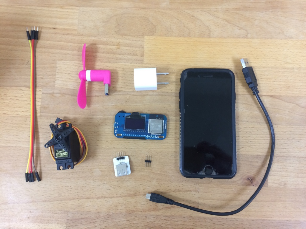
Required Components
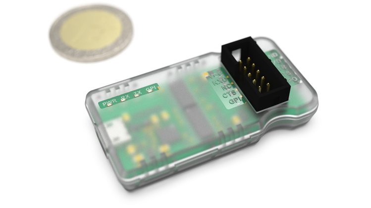
- Obniz
- Servo motor
- Small USB fan
- USB <-> Pin header
- Pin header
- Cable
- USB-Cable
- USB-Adaptor
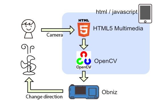
How it works
We use HTML5 Multimedia to use smartphone’s camera.
Step 1 – setting up obniz
To get started, all you need to do is to follow three steps.
1. Connect obniz to wifi
2. Connect devices like LED or motors to obniz
3. Scan QR code of obniz and start programming. You do not need to install any software.
https://youtu.be/3GYG8BjfcXg
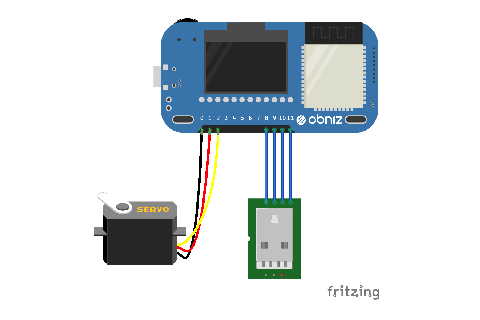
Step 2 – Hardware
We need to follow three steps for the hardware.
- Connect obniz and a servo motor
- Connect Small USB Fan to USB <-> Pin header, and connect it to obniz.
- Connect obniz to Power supply.
Step 3 – software
1. With HTML5 Multimedia, we can get camera data
We use navigator.getUserMedia(). The browser asks user to permit.
Then, callback parameter stream are set to video tag, and display camera pic on html
It is only HTTPS protocol.
<video id="videoInput" autoplay playsinline width=320 height=240>
<button id="startAndStop">Start</button>

<script>
  let videoInput = document.getElementById('videoInput');
  let startAndStop = document.getElementById('startAndStop');

  startAndStop.addEventListener('click', () => {
    if (!streaming) {

      navigator.mediaDevices = navigator.mediaDevices || ((navigator.mozGetUserMedia || navigator.webkitGetUserMedia) ? {
        getUserMedia: function (c) {
          return new Promise(function (y, n) {
            (navigator.mozGetUserMedia ||
                navigator.webkitGetUserMedia).call(navigator, c, y, n);
          });
        }
      } : null);

      if (!navigator.mediaDevices) {
        console.log("getUserMedia() not supported.");
        return;
      }

      const medias = {
        audio: false,
        video: {
          facingMode: "user"
        }
      };

      navigator.mediaDevices.getUserMedia(medias)
          .then(function (stream) {
            streaming = true;
            var video = document.getElementById("videoInput");
            video.src = window.URL.createObjectURL(stream);
            video.onloadedmetadata = function (e) {
              video.play();
              onVideoStarted();
            };
          })
          .catch(function (err) {
            console.error('mediaDevice.getUserMedia() error:' + (error.message || error));
          });

    } else {
      utils.stopCamera();
      onVideoStopped();
    }
  });

  function onVideoStarted() {
    startAndStop.innerText = 'Stop';

   // ...
  }

  function onVideoStopped() {
    startAndStop.innerText = 'Start';

   // ...
  }

</script>
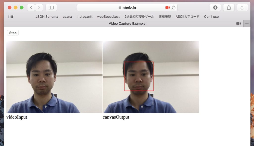
2. Face detect with camera data and OpenCV
We use OpenCV Sample.
haarcascade_frontalface_default.xml is face data, and we use it for detect face.
<canvas id="canvasOutput" width=320 height=240 style="-webkit-font-smoothing:none">

<script src="https://docs.opencv.org/3.4/opencv.js"></script>
<script src="https://webrtc.github.io/adapter/adapter-5.0.4.js" type="text/javascript"></script>
<script src="https://docs.opencv.org/3.4/utils.js" type="text/javascript"></script>

<script>

let streaming = false;

function onVideoStopped() {
streaming = false;
canvasContext.clearRect(0, 0, canvasOutput.width, canvasOutput.height);
startAndStop.innerText = 'Start';
}

let utils = new Utils('errorMessage');

let faceCascadeFile = 'haarcascade_frontalface_default.xml';
utils.createFileFromUrl(faceCascadeFile, 'https://raw.githubusercontent.com/opencv/opencv/master/data/haarcascades/haarcascade_frontalface_default.xml', () => {
startAndStop.removeAttribute('disabled');
});

async function start() {
let video = document.getElementById('videoInput');
let src = new cv.Mat(video.height, video.width, cv.CV_8UC4);
let dst = new cv.Mat(video.height, video.width, cv.CV_8UC4);
let gray = new cv.Mat();
let cap = new cv.VideoCapture(video);
let faces = new cv.RectVector();
let classifier = new cv.CascadeClassifier();


let result = classifier.load("haarcascade_frontalface_default.xml");

const FPS = 30;

function processVideo() {
try {
if (!streaming) {
// clean and stop.
src.delete();
dst.delete();
gray.delete();
faces.delete();
classifier.delete();
return;
}
let begin = Date.now();
// start processing.
cap.read(src);
src.copyTo(dst);
cv.cvtColor(dst, gray, cv.COLOR_RGBA2GRAY, 0);
// detect faces.
classifier.detectMultiScale(gray, faces, 1.1, 3, 0);
// draw faces.
for (let i = 0; i < faces.size(); ++i) {
let face = faces.get(i);
let point1 = new cv.Point(face.x, face.y);
let point2 = new cv.Point(face.x + face.width, face.y + face.height);
cv.rectangle(dst, point1, point2, [255, 0, 0, 255]);
}
cv.imshow('canvasOutput', dst);

// schedule the next one.
let delay = 1000 / FPS - (Date.now() - begin);
setTimeout(processVideo, delay);
} catch (err) {
console.error(err);
}
};

// schedule the first one.
setTimeout(processVideo, 0);

}

</script>
3. Detect x position of your face and rotate the servo motor
The code is not complicated.
Only we need is where we wired obniz to servo motor and USB, and how to rotate the servo motor.
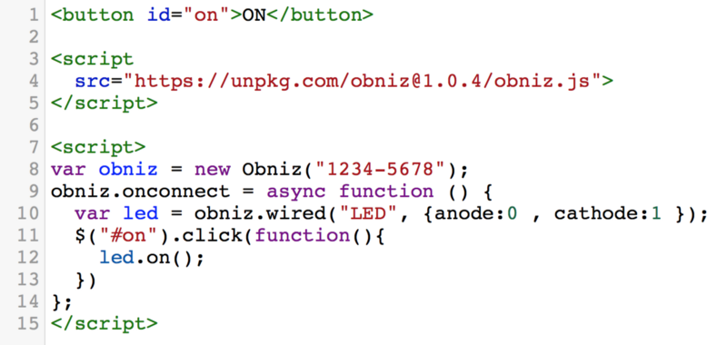
new Obniz(“OBNIZ_ID_HERE”); is the code of connection to obniz
<script src="https://unpkg.com/[email protected]/obniz.js"></script>

<script>
let obniz = new Obniz("OBNIZ_ID_HERE");
let servo;
obniz.onconnect = async () => {
obniz.display.print("ready")
var usb = obniz.wired("USB" , {gnd:11, vcc:8} );
usb.on();

servo = obniz.wired("ServoMotor", {signal:0,vcc:1, gnd:2});

}

if(/* when detect face */){
servo.angle(xPos * 180 / 320);
}

</script>
What is Obniz?
obniz is a cloud-connected IoT development board. You can program on the web browser of any smartphone or computer and the command is sent to obniz through the internet via obniz cloud. By connecting the obniz to the cloud through wifi, users can remotely control devices that are physically connected to obniz.
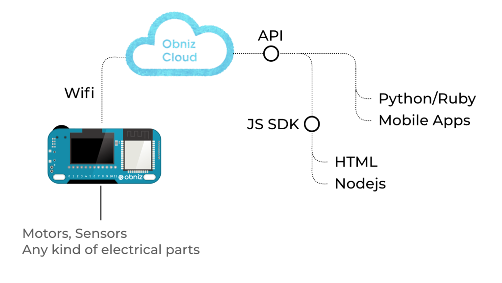
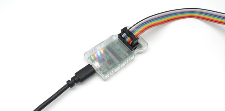
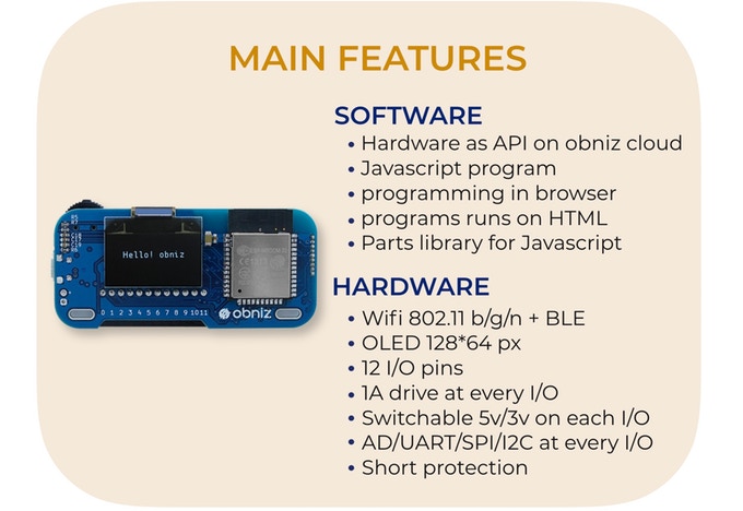
obniz has 12 IO and WiFi-BLE module. It can be controlled through the APIs – REST or WebSocket API – on obniz cloud. Not only simple IO on/off but also UART, I2C, BLE etc can be used by remotely controlling obniz via internet. All you need to do to connect obniz is to input unique ID by scanning QR code. Complicated processes are done by obniz and its cloud. You can just start programming in HTML, browser and circuit have already been integrated. If you write a program to collect sensor values, you can make a chart of the values easily.
In terms of hardware, every IO can drive up to 1A with overcurrect protection, therefore high current demanding devices such as motors can be directly connected to obniz IO. GPIO and AD can be used on every IO. UART, SPI etc peripherals can be assigned to every IO. Even output voltage 3v/5v can be changed by software. Most electrical parts can be connected directly. Embedded parts such as switch, OLED display, and BLE are ready for use on program.
More information on obniz is available on its website
Program
<!-- HTML Example -->

<!DOCTYPE html>
<html>
<head>
<meta charset="utf-8">
<title>Video Capture Example</title>
<meta name="viewport" content="width=device-width,initial-scale=1">
<script src="https://docs.opencv.org/3.4/opencv.js"></script>
<script src="https://obniz.io/js/jquery-3.2.1.min.js"></script>
<script src="https://unpkg.com/[email protected]/obniz.js"></script>
<style>
.refrect-lr {
-webkit-transform: scaleX(-1);
-o-transform: scaleX(-1);
-moz-transform: scaleX(-1);
transform: scaleX(-1);
filter: FlipH;
-ms-filter: "FlipH";
}
</style>
</head>
<body>

<div id="obniz-debug"></div>

<div>
<div class="control">
<button id="startAndStop">Start</button>
</div>
</div>
<p class="err" id="errorMessage"></p>
<div>
<table cellpadding="0" cellspacing="0" width="0" border="0">
<tr>
<td>
<video id="videoInput" autoplay playsinline width=320 height=240 class="refrect-lr"></video>
</td>
<td>
<canvas id="canvasOutput" width=320 height=240 style="-webkit-font-smoothing:none"

class="refrect-lr"></canvas>
</td>
<td></td>
<td></td>
</tr>
<tr>
<td>
<div class="caption">videoInput</div>
</td>
<td>
<div class="caption">canvasOutput</div>
</td>
<td></td>
<td></td>
</tr>
</table>
</div>

<script src="https://webrtc.github.io/adapter/adapter-5.0.4.js" type="text/javascript"></script>
<script src="https://docs.opencv.org/3.4/utils.js" type="text/javascript"></script>
<script type="text/javascript">

let servo;


obniz = new Obniz("OBNIZ_ID_HERE");

obniz.onconnect = async () => {
obniz.display.print("ready")

let usb = obniz.wired("USB", {gnd: 11, vcc: 8});
usb.on();

servo = obniz.wired("ServoMotor", {signal: 0, vcc: 1, gnd: 2});

}

let utils = new Utils('errorMessage');

let faceCascadeFile = 'haarcascade_frontalface_default.xml';
utils.createFileFromUrl(faceCascadeFile, 'https://raw.githubusercontent.com/opencv/opencv/master/data/haarcascades/haarcascade_frontalface_default.xml', () => {
startAndStop.removeAttribute('disabled');
});


let streaming = false;
let videoInput = document.getElementById('videoInput');
let startAndStop = document.getElementById('startAndStop');
let canvasOutput = document.getElementById('canvasOutput');
let canvasContext = canvasOutput.getContext('2d');


startAndStop.addEventListener('click', () => {

if (!streaming) {
utils.clearError();


navigator.mediaDevices = navigator.mediaDevices || ((navigator.mozGetUserMedia || navigator.webkitGetUserMedia) ? {
getUserMedia: function (c) {
return new Promise(function (y, n) {
(navigator.mozGetUserMedia ||
navigator.webkitGetUserMedia).call(navigator, c, y, n);
});
}
} : null);

if (!navigator.mediaDevices) {
console.log("getUserMedia() not supported.");
return;
}

const medias = {
audio: false,
video: {
facingMode: "user"
}
};

navigator.mediaDevices.getUserMedia(medias)
.then(function (stream) {
streaming = true;
var video = document.getElementById("videoInput");
video.src = window.URL.createObjectURL(stream);
video.onloadedmetadata = function (e) {
video.play();
onVideoStarted();
};
})
.catch(function (err) {
console.error('mediaDevice.getUserMedia() error:' + (error.message || error));
});


} else {
utils.stopCamera();
onVideoStopped();
}

});

function onVideoStarted() {
startAndStop.innerText = 'Stop';
start();
}
function onVideoStopped() {
streaming = false;
canvasContext.clearRect(0, 0, canvasOutput.width, canvasOutput.height);
startAndStop.innerText = 'Start';
}

async function start() {
let video = document.getElementById('videoInput');
let src = new cv.Mat(video.height, video.width, cv.CV_8UC4);
let dst = new cv.Mat(video.height, video.width, cv.CV_8UC4);
let gray = new cv.Mat();
let cap = new cv.VideoCapture(video);
let faces = new cv.RectVector();
let classifier = new cv.CascadeClassifier();


let result = classifier.load("haarcascade_frontalface_default.xml");

const FPS = 30;

function processVideo() {
try {
if (!streaming) {
// clean and stop.
src.delete();
dst.delete();
gray.delete();
faces.delete();
classifier.delete();
return;
}
let begin = Date.now();
// start processing.
cap.read(src);
src.copyTo(dst);
cv.cvtColor(dst, gray, cv.COLOR_RGBA2GRAY, 0);
// detect faces.
classifier.detectMultiScale(gray, faces, 1.1, 3, 0);
// draw faces.
for (let i = 0; i < faces.size(); ++i) {
let face = faces.get(i);
let point1 = new cv.Point(face.x, face.y);
let point2 = new cv.Point(face.x + face.width, face.y + face.height);
cv.rectangle(dst, point1, point2, [255, 0, 0, 255]);
}
cv.imshow('canvasOutput', dst);
if (servo && faces.size() > 0) {
let face = faces.get(0);
servo.angle((320 - (face.x + face.width / 2)) * 180 / 320);
}

// schedule the next one.
let delay = 1000 / FPS - (Date.now() - begin);
setTimeout(processVideo, delay);
} catch (err) {
console.error(err);
}
};

// schedule the first one.
setTimeout(processVideo, 0);

}
</script>
</body>
</html>