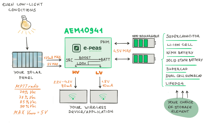
E-peas’ photovoltaic energy harvesting IC solution – AEM10941 – is the next generation integrated energy management subsystem that extracts DC power from up to 7 cells solar panels to simultaneously store energy in a rechargeable element and supply the system with two independent regulated voltages. This allows product designers and engineers to extend battery lifetime and ultimately get rid of the primary energy storage element in a large range of wireless applications like industrial monitoring, home automation, wearables.
The AEM10941 harvests the available input current up to 125 mA. It integrates an ultra-low-power Boost converter to charge a storage element, such as a Li-Ion battery, a thin film battery or a super- or conventional capacitor. The Boost converter operates with input voltages in a range of 50 mV to 5V. With its unique cold-start circuit, it can start operating with empty storage elements at an input voltage as low as 380 mV and an input power of just 3 µW.
The low voltage supply typically drives a microcontroller at 1.8 V. The high voltage supply typically drives a radio transceiver at a configurable voltage. Both are driven by highly efficient LDO (Low Drop-Out) regulators for low noise and high stability.
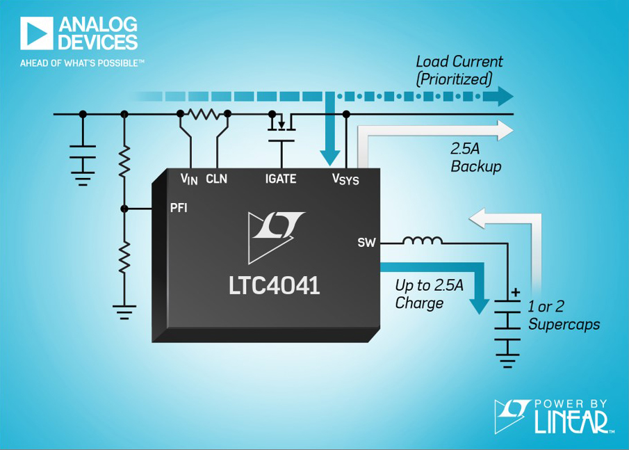
A complete supercapacitor back-up power management system for 2.9 to 5.5V supply rails is available from Analog Devices.
The LTC4041 uses an on-chip bi-directional synchronous converter to provide high efficiency step-down supercapacitor charging. There is also high current, high efficiency boost back-up power. When external power is available, the device operates as a step-down battery charger for one or two supercapacitor cells, giving preference to the system load. When the input supply drops below the adjustable power-fail input (PFI) threshold, the LTC4041 switches to step-up regulator operation, capable of delivering up to 2.5A to the system load from the supercapacitor. During a power fail event, its PowerPath control provides reverse blocking and a seamless switchover from input power to back-up power.
Typical applications for the LTC4041 include ride-through so-called “dying gasp” supplies, high current ride-through 3.0 to 5.0V uninterruptible power supplies (UPS), power meters, industrial alarms, servers and solid state drives (SSDs).
The LTC4041 includes an optional over-voltage protection (OVP) function using an external FET which can protect the IC from input voltages greater than 60V. An internal supercapacitor balancing circuit maintains equal voltages across each supercapacitor and limits the maximum voltage of each supercapacitor to a predetermined value. Its adjustable input current limit function enables operation from a current limited source while prioritising system load current over battery charge current.An external disconnect switch isolates the primary input supply from the system during back-up. The device also includes input current monitoring, an input power fail indicator, and a system power fail indicator.
The LTC4041 is offered in a low profile (0.75mm) 24-lead 4.0 x 5.0mm QFN package with backside metal pad for excellent thermal performance. The device operates from -40 to +125 degrees C, in both E and I grades.
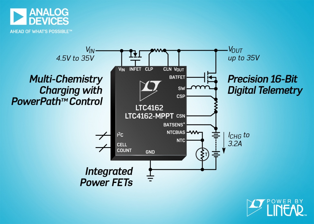
An integrated, high voltage multi-chemistry synchronous monolithic step-down battery charger and PowerPath manager with onboard telemetry functions and optional maximum power point tracking (MPPT) has been announced by Analog Devices. The Power by Linear LTC4162 is 3.2A, 35VIN/35VOUT synchronous monolithic multi-chemistry PowerPath manager/charger with digital I2C telemetry and MPPT operation.
The LTC4162 transfers power from a variety of input sources, such as wall adapters, backplanes and solar panels, to charge a Li-Ion/polymer, LiFePO4 or lead-acid battery stack and provide power to a system load up to 35V. The device provides advanced system monitoring and PowerPath management, plus battery health monitoring. A host microcontroller is required to access the most advanced features of the LTC4162, although the use of the I2C port is optional, says ADI.
The main charging features of the product can be adjusted using pin-strap configurations and programming resistors. The device offers precision ± five per cent charge current regulation up to 3.2A, ±0.75 per cent charge voltage regulation and operates over a 4.5 to 35V input voltage range. Applications include portable medical instruments, USB power delivery (one to five devices), military equipment, industrial handhelds and ruggedised notebook or tablet computers.
The LTC4162 contains a 16-bit analogue-to-digital converter (ADC) that continuously monitors system parameters on command, including input voltage, input current, battery voltage, battery current, output voltage, battery temperature, die temperature and battery series resistance (BSR). All system parameters can be monitored via a two-wire I2C interface, while programmable and maskable alerts ensure that only the information of interest causes an interrupt.
The active maximum power point tracking algorithm globally sweeps an input under-voltage control loop and selects an operating point to maximise power extraction from solar panels and other resistive sources. The LTC4162’s PowerPath topology decouples the output voltage from the battery, thereby allowing a portable product to start-up instantly when a charging source is applied under very low battery voltage conditions.
The LTC4162’s on-board charging profiles are optimised for each of a variety of battery chemistries, including Li-Ion/polymer, LiFePO4 and lead acid. Both charge voltage and charge current can be automatically adjusted based on battery temperature to comply with JEITA guidelines, or custom settings.
The LTC4162 is housed in a 28-lead, 4.0 x 5.0mm QFN package with an exposed metal pad for excellent thermal performance. E- and I-grade devices are guaranteed for operation from –40 to +125 degree C.
Raspberry Pi undeniable has being the template of most (if not all) single board computer esver since its launch in the year 2012. The Raspberry Pi has since seen a breakthrough in several spaces including the hardware industry, STEM Education, computer science, and it is one of the major movers of the maker’s movement making it receive a broad adoption among makers, engineers, students, teachers, programmer, kids, and others.
The Raspberry Pi is referred to as open-source hardware, but the question remains whether the Raspberry Pi is genuinely an open-source hardware. Unlike other open-source hardware like the Arduino, Orange Pi etc, the core of Raspberry Pi which is the Broadcom chip is not in anyway open. Aside from the fact it is not open, getting your hands on that chip is also highly unlikely unless you are ready to splash some thousands to millions of dollars.
The BlueBerry Pi
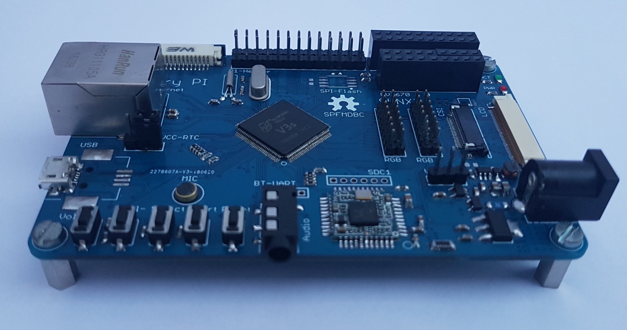
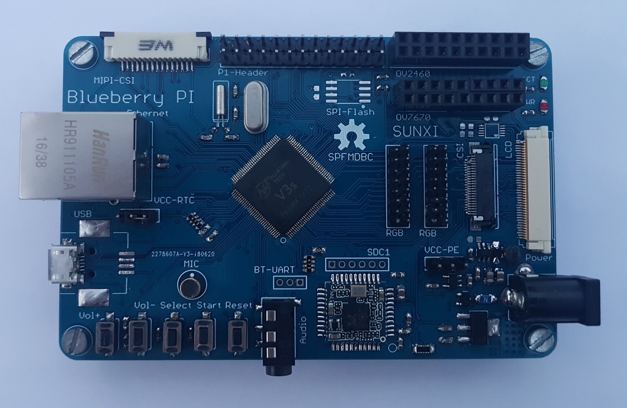
Hackers and makers have been looking into building their own Raspberry Pi just as we have seen makers rebuilding their own Arduino and even going the extent of making it better. Aside from being partially open, the PCB on the Raspberry Pi alone uses a six layer board with tightly spaced components making it a no-go build it yourself arena. But if the relentless urge for DIY still holds on you, then the BlueBerry Pi made by Marcel Thürmer might be your answer.
The Blueberry Pi project will allow hardcore DIYs to build their own Raspberry Pi. At the core of the Blueberry Pi is the more friendly Allwinner V3s, a SoC intended for the action camera market. The V3s is a System on Chip with an Arm Cortex-A7 running at 1.2GHz, accompanied with a much smaller 64 MB of RAM as compared to the 512MB found on the Raspberry Pi Zero.
The board doesn’t come in the standard Raspberry Pi form factor, and instead of the known 40-pin GPIO header available on the newer generation Raspberry Pi, it has an older 26-pin header from the original Pi labeled as the “P1 Header” on the board. The board comes with some similar features found on the Raspberry Pi like a 100MBps Ethernet, SPI Flash, a USB host port, an audio jack, an SD card slot, MIPI CSI interface, and both WiFi and BLE. It comes with an onboard microphone, four buttons, plus two interesting OV2640 and OV7670 pin headers.
Due to the nature of the SoCs being used, the whole board design falls into the more straightforward and cost-effective two-layer PCB making it easier for similar hackers to build their own Pi. According to Marcel Thürmer –
“The Blueberry PI can boot from an SD card or SPI Flash. Since the V3s doesn’t have a standard video output, I’m planning on creating a video add on board which provides VGA or HDMI. In combination with the ADV7611 it is possible to capture HDMI.”—
So if you are thinking of getting started building yours, the whole board information is available on the project’s GitHub repo which includes design files and u-boot instructions. Of course, don’t expect to get a similar performance as the Raspberry Pi or an easy build, but it is still worth it journey.
Over the past few tutorials, we explored several ways to further reduce the power consumption for Arduino based projects so they can last for a long period of time running on the inexpensive AAA batteries. We have tried different approaches like the more recent tutorial on using Atmega328p instead of an Arduino board and as the result of the tutorials showed, we were able to reduce power consumption considerably. With all the techniques used to reduce the power, the Arduino still consumed too much current especially the amount of current drawn when the Arduino is in the Idle state. To resolve this, we will need a solution that shuts the Arduino off when the system is idle to preserve battery charge and this is the focus of today’s tutorial.
This project works like most digital watches when you turn them on, it shows you the needed information and after a while goes off to preserve the battery. A typical Arduino consumes about 40mA of current in an idle state while the Atmega328p consumes around 20mA when in the same state. We can conserve this power by using this way to turn on/off the Arduino.
The project basically uses a transistor as a switch to connect the power lines of Arduino to the battery.
Required Components
The following components are required to build this project;
As usual, the exact components used for this tutorial can be bought via the links attached to each of the components above.
Schematics
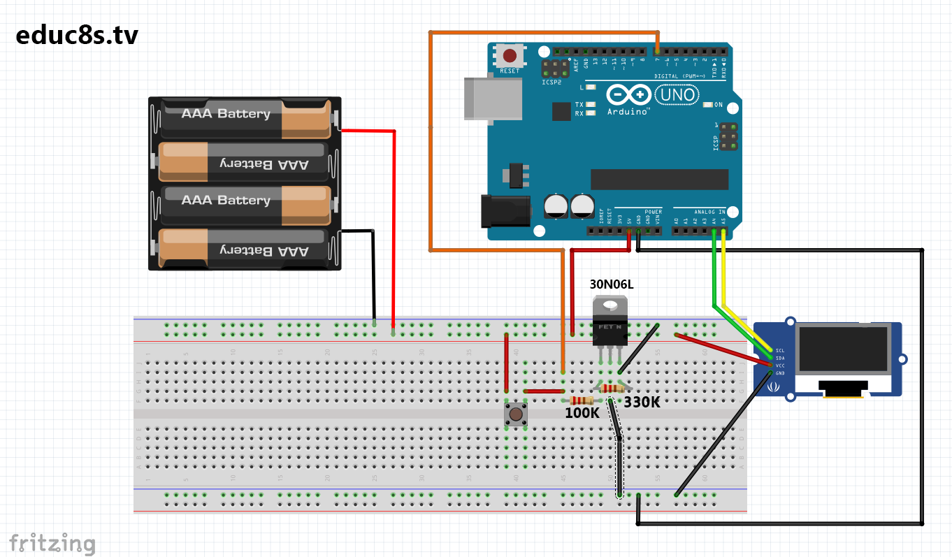
With all the components acquired, connect them as shown in the schematics below:
Schematics
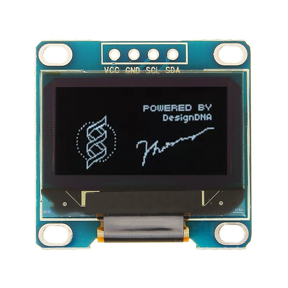
Connecting the components for this project is very easy as there are very few connections to the Arduino. The gate pin of the MOSFET is connected to pin D7 and the OLED display is connected to the I2C pins of the Arduino. A pin map of the connection between the OLED display and the Arduino is shown below;
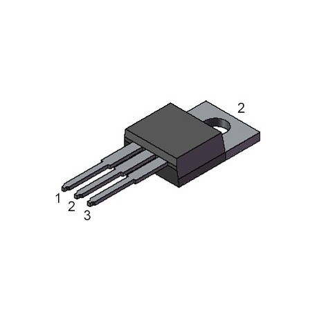
The 30N06L MOSFET pinout is shown below and is the control element of this project. When a signal/voltage is applied to the gate (Pin 1 below) of the MOSFET, it allows current to flow between the source (pin 2 below) and the drain (pin 3 below) and when there is no voltage/signal at the gate pin, the current flow between the source and the drain is blocked.
30N06L Mosfet Pinout
For our application, the MOSFET was connected in such a way that the ground connections from the battery go through to the Arduino. This gives the MOSFET the ability to provide control and turn the Arduino on or off as a complete path of current flow through the Arduino can only be achieved through it. When the button is pressed, the Arduino runs a countdown after which, it drives LOW the Arduino pin D7, which is connected to the gate of the MOSFET. Once this pin goes low, the current flow between the source of the MOSFET and the drain is blocked. With this connection blocked, the ground pin of the Arduino becomes disconnected from the ground pin of the battery and as a result there is no complete path for current to flow and the Arduino goes off. When the button is pressed again, power is supplied once more to the gate of the FET, the Arduino comes on and the process starts all over again.
Code
The code for this project is quite simple as all we do is to display a countdown on the OLED and turn off the Arduino after the countdown. We will use the Adafruit GFX library to easily send data from the Arduino to the OLED Display.
To briefly explain the code, we start by including the libraries needed to use the OLED displays after which we define the pin of the Arduino to which the gate pin of the MOSFET is connected.
//Written By Nick Koumaris
//info@educ8s.tv

#include <Adafruit_SSD1306.h>
#include <Adafruit_GFX.h>

// Pin definitions
#define OLED_RESET 4
const int MOSFETPIN =  7;
Next is the void setup() function. Since the code for this project runs only once everytime the Arduino comes on, I decided to keep all the code within the setup() function and leave the void loop() function empty.
We start by setting the pinMode of the MOSFET pin as output and setting it to HIGH, after which we create an object of the OLED display library.
Next, we issue the commands to display the “power-off” text on the display and start the countdown process from 5 to 1 after which we turn the MOSFET pin low, using the digital write function.
As mentioned earlier, we will leave the void loop() function empty since the code will only be running once everytime the Arduino goes on.
The complete code for the project is attached to the zip file under the download section.
Demo
Copy the code and Upload to your Arduino board, you should see the countdown on the display after which the system goes off. The process can be repeated by pressing the button.
As simple as this project looks, a lot of power is being conserved and this makes the setup ideal for projects that do not require the Arduino staying on while idle. A good example of projects that can be built based on this is a clock system so time is only displayed when the button is pressed.
That’s it for this tutorial guys, feel free to drop any questions you might have as regards this project under the comment section.
The video version of this tutorial is available on youtube.
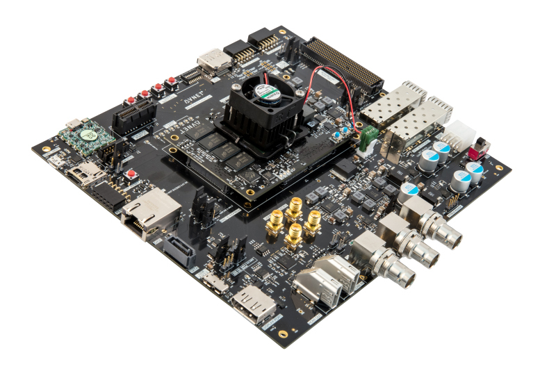
Avnet a leading global technology solutions provider, today released the UltraZed-EV™ Starter Kit, providing designers with the core tools necessary to shape the future of advanced embedded vision design and turn their ideas into reality. By bundling the new UltraZed-EV System on Module (SOM) and Carrier Card, Avnet has created a complete platform for prototyping and evaluating embedded video processing systems.
The UltraZed-EV Starter Kit is based on the Xilinx® Zynq® UltraScale+™ MPSoC EV device family and is the latest addition to Avnet’s Zedboard portfolio of modules and peripherals supporting customer product development leveraging SoC technology from Xilinx. The full Zedboard family includes the MicroZed, PicoZed, UltraZed and MiniZed and for applications including embedded vision, IoT, IIoT, voice processing and software defined radio.
“Providing lower-power, higher-efficiency machines with the ability to see, sense and immediately respond to inputs creates unique opportunities for system differentiation,” said Dan Rozwood, UltraZed project engineer for Avnet. “By leveraging the scalability and flexibility offered by the Zynq UltraScale+ MPSoC portfolio, Avnet’s new UltraZed-EV Starter Kit allows designers to focus on their product’s feature set rather than high-speed, digital design infrastructure.”
“Avnet’s UltraZed-EV Starter Kit and accompanying SOMs give embedded vision and multimedia application developers access to the Zynq UltraScale+ EV device family to offer power-efficient solutions to many of today’s video-centric edge device designs, while future-proofing for the evolving standards,” said Sumit Shah, director of product marketing at Xilinx. “Complemented by full software development support, this platform is provided with Embedded Linux-based reference designs, which in conjunction with Xilinx’s extensive video IP subsystem portfolio, enable customers to develop an end-to-end platform to immediately start application development.”
Technical Highlights:
The UltraZed-EV SOM
High-performance, full-featured SOM with onboard dual system memory, high-speed transceivers, Ethernet, USB, and configuration memory
Easy access to 152 user I/O pins, 26 processing system (PS) MIO pins, four high-speed PS-GTR transceivers along with four GTR reference clock inputs and 16 programmable logic (PL) high-speed GTH transceivers, and 16 programmable logic (PL) high-speed GTH transceivers
Zynq UltraScale+ MPSoC EV with integrated H.264/H.265 video codec unit, capable of simultaneous encode and decode at up to 4k60
The UltraZed-EV Carrier Card
Mates with the UltraZed-EV SOM via two 200-pin Micro Headers, connecting the UltraZed-EV PL I/O and transceivers to FMC HPC slot, LVDS touch panel interface, SFP+ interface, HDMI In/Out, 3G-SDI In/Out, pushbutton switches, DIP switches, LEDs, Xilinx System Monitor (SYSMON), clock generators, and two Digilent Pmod™ compatible interfaces
Third 120-pin Micro Header provides access to the UltraZed-EV SOM PS MIO and GTR transceiver pins, as well as USB and Tri-Ethernet interfaces
The UltraZed-EV SOM PS MIO and GTR pins implement the microSD card, Pmod, USB 2.0/3.0, Gigabit Ethernet, SATA host, DisplayPort, PCIe® root port, dual USB-UART, user LED, and switch and MAC address device interfaces
Now available to customers in the Americas, EMEA, Asia, and Japan, the UltraZed-EV Starter Kit is priced at $1,595. The UltraZed I/O Carrier Card can be purchased for $649, and the UltraZed-EV SOM extended temp and industrial temp versions are available for $999 and $1,199 respectively.
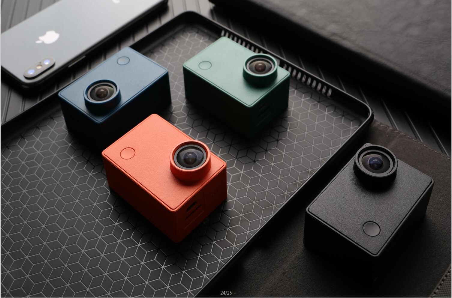
Action cameras are becoming a buzz in the last few years, and the likes of GoPro have become the face of this emerging market, just like the way the iPhone was the default standard for the smartphone industry, GoPro camera has been the go-to camera for the Action camera industry. Despite the awesomeness of Action cameras, they usually come with one major limiting factor which is the cost. The likes of GoPro and another similar Action camera typically cost a fortune and they are not that affordable to the everyday users.
What if we could still get the same similar high performance as the GoPro HERO5 at a fraction of the cost? Yes, it is possible, and the likes of TRAWO by APEMAN made that possible, but the newly launched Seabird 4K Camera goes the extra mile regarding bringing down the cost of an action camera down to less than $100.
The Seabird 4K Camera is a high-performance FHD 4K Action Camera that promises so much. After recently laying my hand on the currently crowdfunding camera, I got marveled at the capabilities of the budget camera. Not only does it do the job well, but it also offers some elegance of class into it with its classy and appealing body.
The Seabird camera is capable of achieving 4K capturing and its video resolution can go as high as 4K (which is 4X more detail than HD) at an outstanding 30fps. Like other similar action cameras, the seabird still images captures at 12Mega Pixels providing crisp, clear images. The camera is capable of slow-motion recording on a 720p resolution at 120fps, of course, that’s not HD, but it is still good enough.
The seabird still images can be taken in single, a burst of 3p, 5p, and 10p, timer mode, and lastly a time-lapse mode giving users fantastic shooting experience and options At the core of the seabird is the HiSilicon Hi3559, 1/3.06“ CMOS technology, supporting a maximum of 60Mbps encoding, 1.12um pixel, and 4K@30fps recording. The below shows some crisp, clear images taken from my Seabird –
pic
pic
pic
pic
pic
pic
Features
4K video capture at 30fps
Powered by HiSilicon Hi3559
7 Layer Glass Lens
12MP HDR still images
155° Wide FOV
Remote Control and Viewing
F2.6 Aperture
6-Axis Gyros stabilization technology
Touch-enabled display
Wi-Fi Control
The camera lens is built around a 7 layer of glass, and capable of 155° Field of View (FOV) giving users the ability to capture a broad view and also fast-moving objects. The camera is built around an F2.6 aperture same as found in most other action cameras which will make it not too ideal for low light conditions but then, what sort of actions or sports will you be doing in a low light environment.
Based on the fast-moving video capturing taken, the Seabird image stabilization and correction is something to be proud of. The camera somehow creates something like an image buffer for smooth and steady photos and videos. This capability is possible due to the inbuilt 6-axis gyros that detect angular velocity, along with dynamic compensation for shooting scenes, keeping shots stable and detailed. Comes with lens distortion correction(LDC) for correcting distortion in real-time.
Also, the Seabird provides support for Wi-Fi and Bluetooth allowing it to connect to the Seabird app for image capturing and recording, but the Bluetooth doesn’t seem to be usable as at this point. The Seabird camera comes with a 1050mAH battery which should last for a couple of hours depending on the mode of operation.
Seabird isn’t waterproof on its own; it requires a waterproof case which is available for purchase as well. After some time using the camera, it might look as if the images are blurry when looking at the 59.2 x 41 x 29.9 mm camera screen but they are not. The camera creates a low-quality version of every picture or video taken so that it can be appropriately displayed on the camera screen. The user can see the real high-quality image if downloaded to a computer or mobile phone. Seabird also supports audio recording during the video capturing, but this option is disabled by default, you will have to enable it manually. Interesting enough, the audio is pretty clear and audible considering the device small factor.
Seabird is one of the accessories you can confidently take with you to capture some of life best moment. Seabird is currently running a crowdfunding campaign on IndieGoGo, and the campaign has already exceeded its minimum goal. The Seabird camera package is starting at $89 for a single Seabird and to about $128 for a Seabird with a waterproof case and a floating rod. More information is available on the product campaign page.
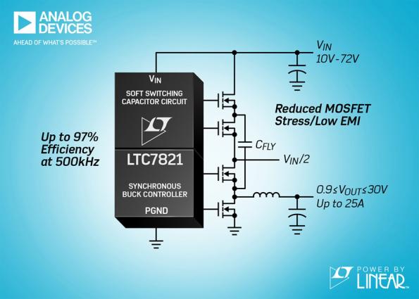
The LTC7821, an industry first hybrid step-down synchronous controller that merges a switched capacitor circuit with a synchronous step-down controller, enables up to a 50% reduction in DC/DC converter size compared to traditional solutions.
The LTC7821 uses a proprietary architecture that merges a soft switching charge pump topology with a synchro- nous step-down converter to provide superior efficiency and EMI performance compared to traditional switching architectures.
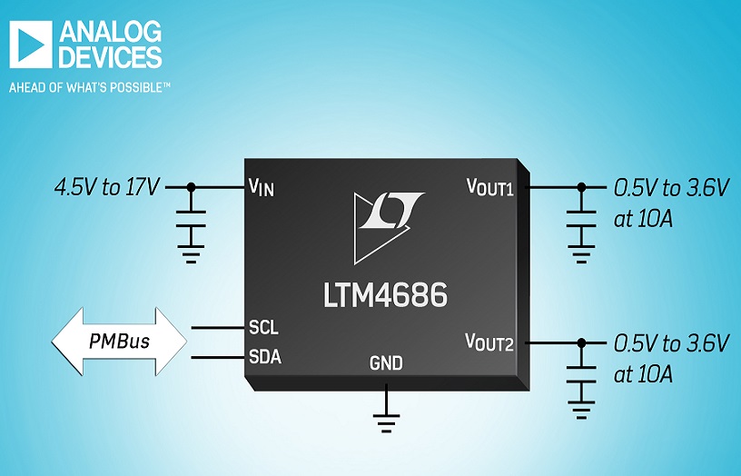
Available as either a dual 10A or single 20A thin uModule regulator, the LTM4686 has a PMBus interface and is housed in a 16 x 11.9 x 1.82mm LGA package.
The Power by Linear regulator’s low height allows the it to be placed on a PC board very close to its load such as an FPGA or ASIC, while sharing one heat sink covering both low profile packages. The package allows the LTM4686 to be mounted on the back of a PCB, freeing top space for components such as memory and transceiver ICs, explains Analog Devices. This makes the LTM4686 suitable for height-restricted applications such as rack-mounted telecomms switches and routers, raid systems, and test and measurement equipment.
The PMBus interface enables users to measure and alter key power parameters such as voltage, load current and temperature. Users can also program sequencing, fault thresholds and responses via PMBus, storing values and fault log data in the onboard EEPROM.
The LTM4686 operates from 4.5 to 17V and the LTM4686-1 operates from 2.375 to 17V input supplies. The modules regulate an output from 0.5 to 3.6V with ±0.5 per cent maximum DC output error over temperature, – 40 to +125 degree C.They deliver 80 per cent efficiency at 12VIN to 1.0VOUT at a full load condition and can deliver 18A from a 5VIN to a 1VOUT at 85 degree C ambient with 400LFM air flow. There is also current mode control in a parallel configuration, to deliver increased output current. Internal switching frequency is settable from 250kHz to 1MHz and can be synchronised to an external clock from 250kHz to 1MHz for noise-sensitive applications.
The LTM4686 configurable offers protection features, including over-voltage and under-voltage, over-current and over-temperature. If a fault occurs, data is saved automatically to the EEPROM, and the fault log can be retrieved over an I2C interface, where it can then be analysed, advises Analog Devices. The LTpowerPlay GUI DC1613 USB-to-PMBus converter VDC2086 programing adapter and demo kits are available to evaluate the performance of the LTM4686.
To get started, all you need to do is to follow three steps.
Connect obniz to wifi
Connect devices like LED or motors to obniz
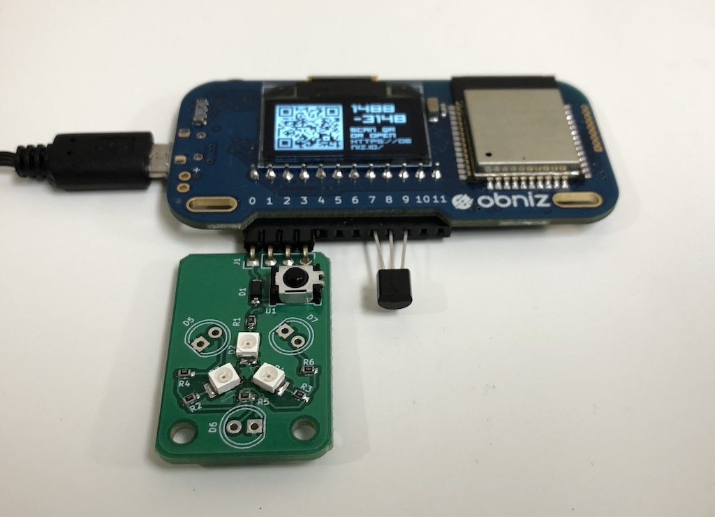
Scan QR code of obniz and start programming. You do not need to install any software.
Step 2
Connect IR module and LM32DZ to obniz as below and place it in your house.
Step 3
Write the program written in the program section. You need to change obniz ID in the program to yours. By clicking “save & open,” you can see the room temperature.
Step 4
Record your air conditioner’s remote signal for ON/OFF.
The example program contains comment outed code for IR receiver. Remove the comment out and record your air conditioner’s ON/OFF signal. Your signal will be shown in the log.
Put the recorded data array into your program.
Use it!
Just open the HTML with your smartphone. You can control your air conditioner from everywhere in the world!
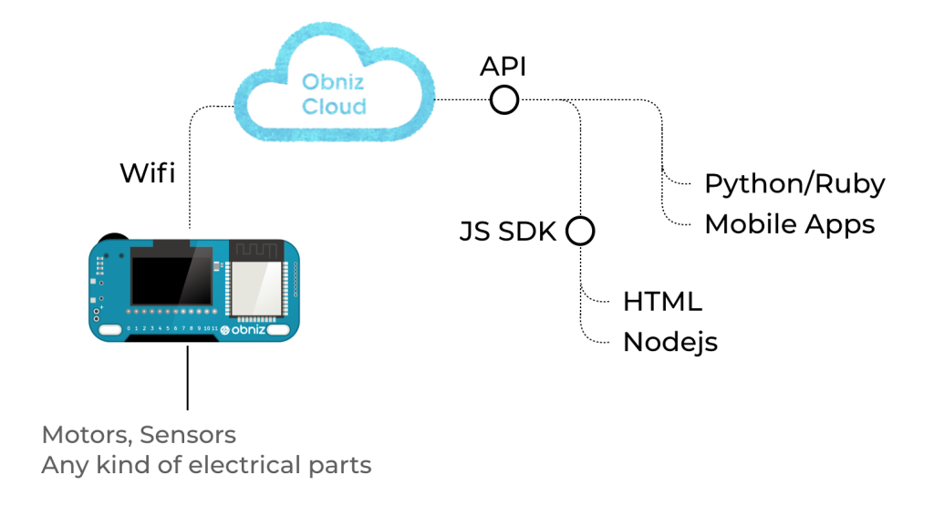
What is Obniz?
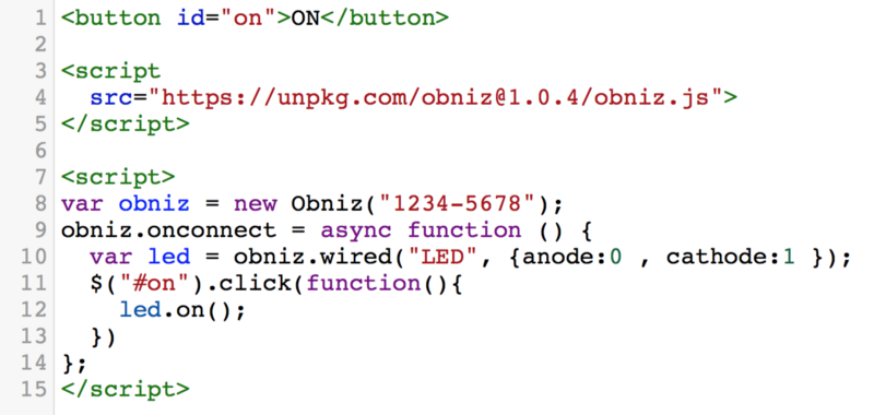
obniz is a cloud-connected IoT development board. You can program on the web browser of any smartphone or computer and the command is sent to obniz through the internet via obniz cloud. By connecting the obniz to the cloud through wifi, users can remotely control devices that are physically connected to obniz.
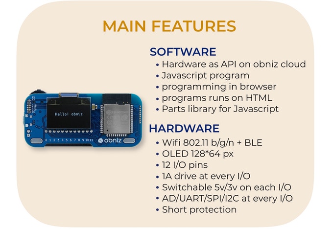
obniz has 12 IO and WiFi-BLE module. It can be controlled through the APIs – REST or WebSocket API – on obniz cloud. Not only simple IO on/off but also UART, I2C, BLE etc can be used by remotely controlling obniz via internet. All you need to do to connect obniz is to input unique ID by scanning QR code. Complicated processes are done by obniz and its cloud. You can just start programming in HTML, browser and circuit have already been integrated. If you write a program to collect sensor values, you can make a chart of the values easily.
In terms of hardware, every IO can drive up to 1A with overcorrect protection, therefore high current demanding devices such as motors can be directly connected to obniz IO. GPIO and AD can be used on every IO. UART, SPI etc peripherals can be assigned to every IO. Even output voltage 3v/5v can be changed by software. Most electrical parts can be connected directly. Embedded parts such as switch, OLED display, and BLE are ready for use on program.
More information on obniz is available on its website
Program
<!-- HTML Example -->


<html>
<head>
  <meta name="viewport" content="width=device-width, initial-scale=1">
  <link rel="stylesheet" href="https://stackpath.bootstrapcdn.com/bootstrap/4.1.1/css/bootstrap.min.css">
  <script src="https://obniz.io/js/jquery-3.2.1.min.js"></script>
  <script src="https://unpkg.com/[email protected]/obniz.js"></script>

</head>
<body>

<div id="obniz-debug"></div>

<h1 id="temp">Measuring...</h1>

<p>
  <button id="on" class="btn btn-primary btn-block">Turn ON</button>
</p>
<p>
  <button id="off" class="btn btn-primary btn-block">Turn OFF</button>
</p>

<script>

var obniz = new Obniz("OBNIZ_ID_HERE");

obniz.onconnect = async function () {

  //var sensor = obniz.wired('IRSensor', {vcc:0, gnd:3, output: 2});
  //sensor.start(function (arr) {
  //  console.log('detected!!')
  //  console.log(JSON.stringify(arr));
  //})

  // Javascript Example
  var tempsens = obniz.wired("LM35DZ",   { gnd:7 , output:8, vcc:9});
  tempsens.onchange = function(temp){
    $("#temp").text('' + parseInt(temp)+ ' degree')
    obniz.display.clear();
    obniz.display.font('Avenir', 60)
    obniz.display.print('' + parseInt(temp) + '℃')
  };

  var infraredLed = obniz.wired('InfraredLED', {anode: 1, cathode: 3});

  $("#on").click(function(){
    // your value for ON here.
    infraredLed.send([])
  })

  $("#off").click(function(){
   // your value for OFF here
    infraredLed.send([])
  })
}


</script>
</body>
</html>