uStepper – Controlling Stepper Motor with ease

But what is uStepper?

In short, uStepper is a product, improving performance of a motor type called “stepper motors”. Stepper motors are used in a wide range of applications where you have to move something, a certain distance, precisely! For example, they are used in your inkjet printer for moving the ink cartridge back and forth over the paper. Stepper motors are precise and really cheap compared to the alternative, Servo motors.

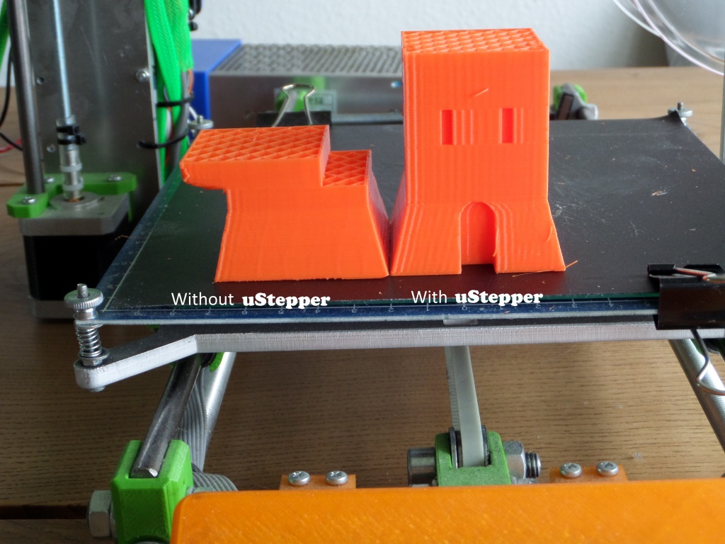
There are one drawback of the steppers though – you actually can’t tell if they move to the position you tell it. If you try to block the path of the ink-jet head, while your printer is printing, it will not recover from this. The printer is rather dependent on the stepper operating with high precision so that you get something readable on your paper!

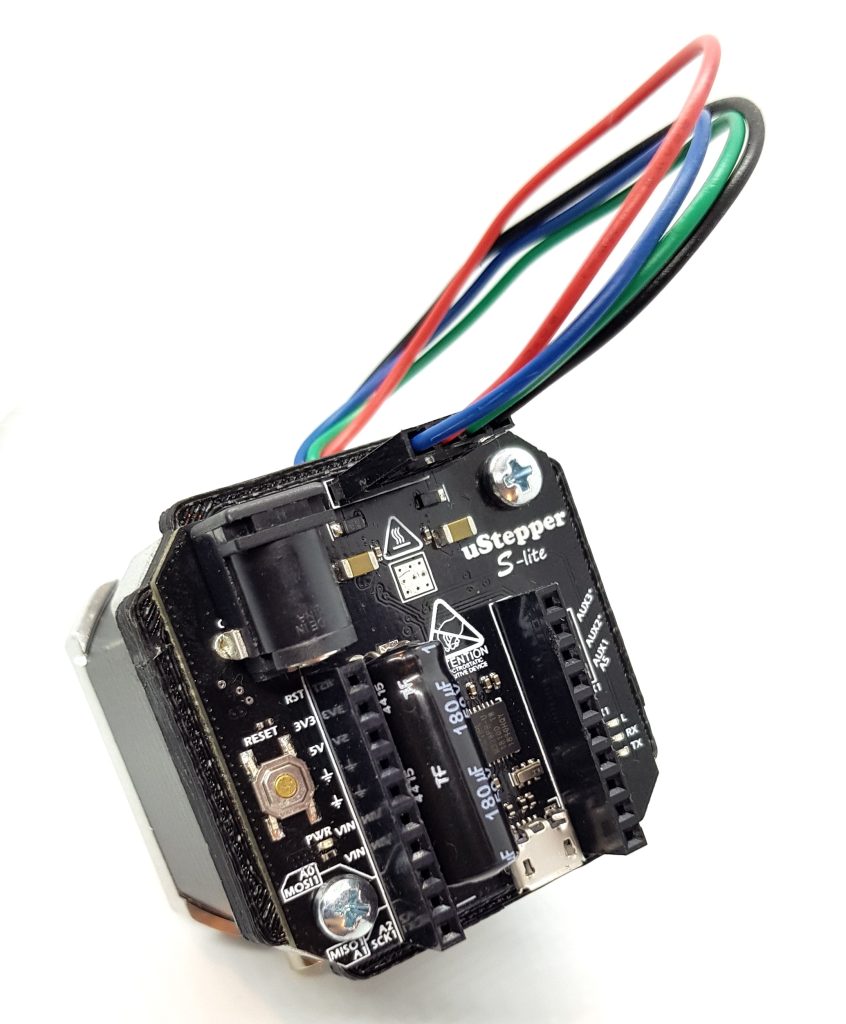
The same happens in most of the applications using stepper motors, including 3D printers where the type of steppers, which uStepper is designed for, are primarily used. What uStepper does, is that it removes this drawback by continuously monitoring where it is, and where it should be. Thus, uStepper can compensate if anything goes wrong – this is what we call operating with feedback.

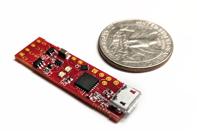
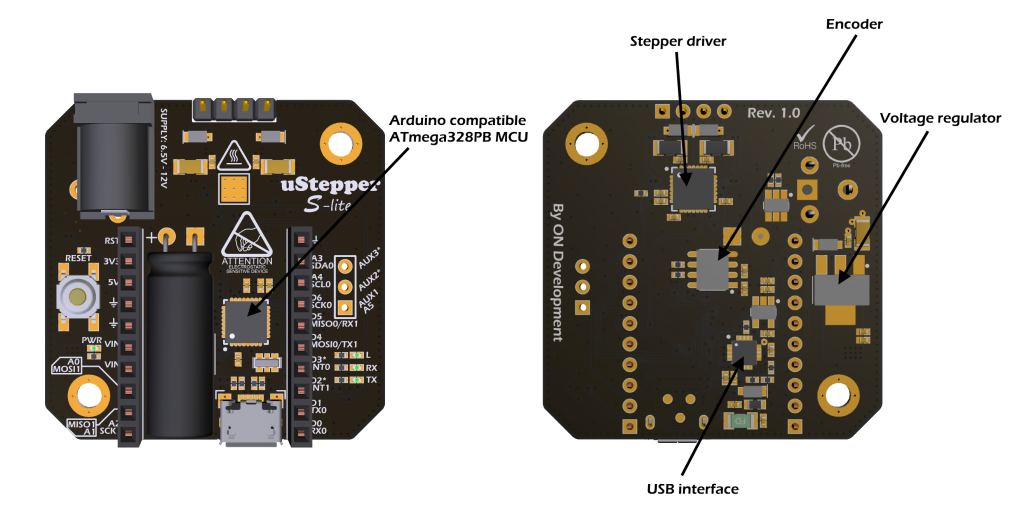
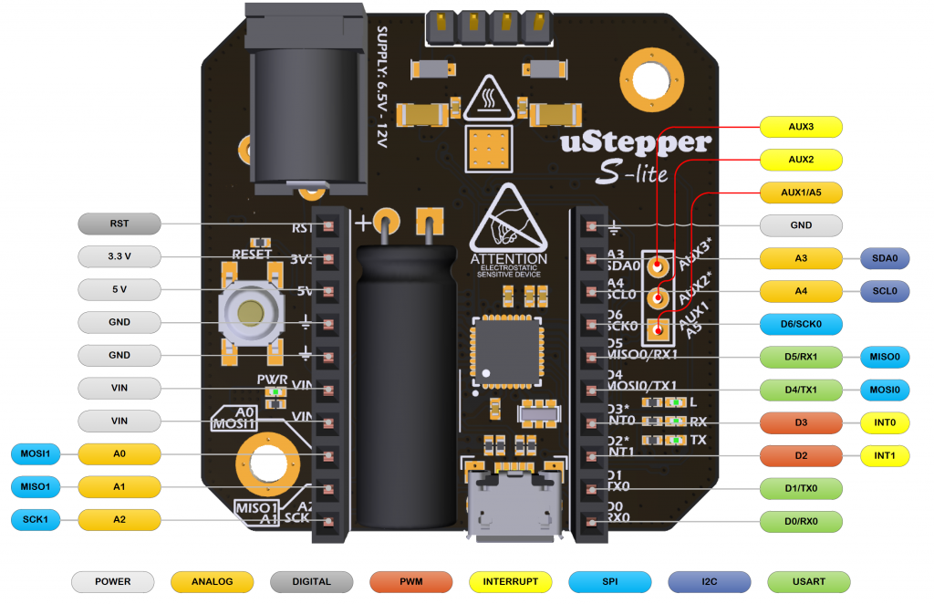
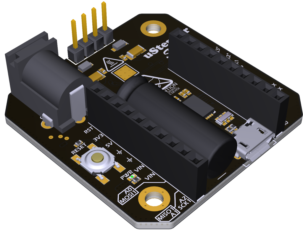
uStepper both has the ability to drive the stepper motor, monitor position and has an onboard programmable microcontroller with a wide range of available inputs and outputs. All this is packed into a very small printed circuit board that fits right on the back of those small stepper motors (which are referred to as NEMA 17).

To make uStepper accessible for both professionals, hobbyists and students, it is compatible with the Arduino IDE. Here you can easily program your uStepper to do exactly what you need it to do!

Who is the target audience for uStepper?

As mentioned previously uStepper is Arduino based and addresses both students, hobbyists and the technician/engineer making for example a test-setups. We focus a lot on the educational sector and have made a product which we believe makes learning with Arduino a lot more fun! Besides the uStepper board, we have made an application example – the uStepper Robot Arm, which gives uStepper a new dimension and addresses the more advanced users. We have sold the uStepper and the uStepper Robot Arm to several Universities around the world, including Aalborg university where we still have a close bond to the professors and employees.

Where is uStepper today?

We started the company behind uStepper, ON Development, back in August 2015 and have since then sold around 2500 uStepper boards. During that time, we have continuously developed the code and applications for the product, and recently expanded our team by hiring an electronics engineering student from Aalborg University. Since 2015 a lot has happened on the market for electronic components, and we have therefore decided to launch a new line of uStepper boards which we will finance by the use of crowdfunding. The line of products will of course offer a uStepper board with improved performance on all parameters, a cheaper “lite” version and potentially a large and powerful version if we reach stretch goals in our campaign. The exact details of the new product line specifications will be disclosed at campaign launch !

We will launch the campaign on 15th of August 2018 – precisely 3 years after we founded ON Development IVS. We (both founders) graduated at Aalborg University one year ago and have alongside uStepper full time jobs as developers within hardware and embedded software.

Why crowdfunding again?

Crowdfunding is a funny thing where success is not necessarily coming to those that have the smartest product, but depends heavily on the publicity you get and the graphic material you provide on the campaign page. Non-the less, it’s a way which provides a good indicator of market potential and also makes it possible to finance the production of the first batches by pre-orders. The value of publicity provided by crowdfunding alone should not be underestimated either, and is exactly for these reasons that we chose to do yet another crowdfunding campaign.

If you want to know more about uStepper and maybe even support our campaign, visit www.ustepper.com where there will also be a link to the campaign page shortly!

Femtosecond Electronics With Plasmonic Hot Electron Nano-emitters

A team led by the Technical University of Munich (TUM) physicists Alexander Holleitner and Reinhard Kienberger has found success for the first time in generating ultrashort electric pulses on a chip. They made this possible by using asymmetric metal antennas only a few nanometers in dimension, then running the signals a few millimeters above the surface and receiving them in a controlled way.

Traditional electronics allow frequencies up to around 100 GHz. Optoelectronics can produce electric pulses at 10 THz range by applying electromagnetic phenomenon. The range in between them is referred as the terahertz gap, since components for signal generation, conversion, and detection have been remarkably difficult to achieve.

The TUM physicists succeeded in generating electric pulses in the frequency range up to 10 THz using tiny, so-called plasmonic antennas and run them over a chip. Researchers call the antennas plasmonic because of their shape, they amplify the light intensity at the metal surfaces. The shape of these plasmonic antennas is very important. They are asymmetrical in shape. One side of the nanometer-sized metal structures is more pointed than the other. When a lens-focused laser pulse excites the antennas, they emit more electrons on their pointed side than on the opposite flat ones. An electric current flows between the contacts — but only as long as the antennas are excited with the laser light.

Femtosecond near-field coupling of NIR pulses to THz stripline modes

In photoemission, the light pulse causes electrons to be emitted from the metal into the vacuum,

explains Christoph Karnetzky, lead author of the Nature paper.

All the lighting effects are stronger on the sharp side, including the photoemission that we use to generate a small amount of current. The light pulses were present in only a few femtoseconds.

Correspondingly short were the electrical pulses in the antennas.  In this way, a femtosecond laser pulse with a frequency of 200 THz could generate an ultra-short THz signal with a frequency of up to 10 THz in the circuits on the chip, according to Karnetzky.

The researchers chose sapphire as the chip material, because it cannot be excited optically and, thus, causes no interference. With an eye on future applications, they used 1.5-micron wavelength lasers deployed in traditional internet fiber-optic cables. Holleitner and his colleagues also made yet another amazing observation that both the electrical and the THz pulses were non-linearly dependent on the excitation power of the laser used. This means that the photoemission in the antennas is triggered by the absorption of multiple photons per light pulse.

Alexander Holleitner said,

Such fast, nonlinear on-chip pulses did not exist hitherto

Utilizing this effect he hopes to discover even faster tunnel emission effects in the antennas and to use them for chip applications.

ATmega32U4-Based Synchronous MPPT Buck Solar Charger

You want to maximize the power output of your solar panel? Then you need a maximum power point tracking charge controller! Source files here.

Features:

  • Programmable with Arduino IDE
  • Input voltage: 15 – 22V
  • Output voltage: 1 – 14.4V
  • Simple MPPT (Maximum Power Point Tracking) solar charge controller for 18V solar panels
  • Proper buck converter topology, which increases the current on the output side, not just PWM
  • SparkFun Pro Micro 5V, 16MHz or 3.3V, 8MHz (3.3V recommended, more efficient)
  • ACS712 current sensor (5A version) on the output side
  • Voltage dividers for voltage measurement on panel and output side
  • Two N-channel MOSFETs, driven by IR2104 half bridge driver, inductor (synchronous buck converter)
  • Supplied by the panel voltage, so it can’t drain your battery during the night
  • Working frequency 31.5kHz
  • WARNING! This device is not intended to drive 5V USB devices directly. Do it at your own risk!
  • Always use a regulated 5V USB adapter on the output! Otherwise, voltage glichtes may damage your USB device!
  • This controller is COMMON NEGATIVE
  • Three operation modes: MPPT, CV, CC
  • SD card data logger for time, voltage and current. You can import the txt files in Excel
  • WARNING! Always adjust output voltage and output current limits according to your battery type!!
  • Efficiency between 84% and 92% (excluding board supply current of about 75mA)

ATmega32U4-Based Synchronous MPPT Buck Solar Charger – [Link]

Microchip’s MCP1640 – Super-Effective Battery Power

Designers working on line-powered systems are in luck…

Designers working on line-powered systems are in luck; whilst wasting power is always bad, a few mA of waste don’t really matter. When working on battery powered systems, every bit of energy helps – an efficient switching regulator can be helpful in various ways.

First of all, the holy grail of battery powered systems is connecting your electronics directly to the battery. Controllers with a wide input range can “float” around the battery voltage, thereby eliminating switching losses completely. Sadly, this is not always possible – LCD modules and various other elements demand fixed voltages or tight voltage ranges.

In this case, a highly efficient voltage regulator can be valuable. Microchip’s MCP1640 boasts with a 96% conversion rate, and furthermore it comes with a power-saving shutdown mode as shown in figure A.

Due to the high switching frequency – the PWM modules work at 500KhZ – the inductors required are small; their weight is comparable with that of SMD resistors, thereby ensuring “minimal grief” when used in surface-mount form factors. […continue reading]

UDOO BOLT, A Supercomputer with twice the Power of a MacBook Pro 13

One thing technology has taught us in the last few years, is the so-called powerful devices of yesterday, will not match the devices of today or tomorrow and this is something that is transcending in the hardware industry. Maker’s board have seen a drastic improvement ever since the first Arduino and the Rasberry Pi Single Board Computer were launched. Startups, makers, engineers and even the big corporations like Intel and Nvidia have all joined in improving the maker’s ecosystem with the launch of their own boards.

UDOO Bolt

Improvements will always keep coming and one board that is going to redefine the maker’s ecosystem is the newly crowdfunded UDOO Bolt. We have seen boards like the Pi 3, Asus TinkerBoard, Nvidia Jetson and other high-performance boards, but the UDOO Bolt brings a new authority to this space. A maker board that carries an exceptional punch – A supercomputer in a maker footprint.

UDOO, an Indie developer company has released a new maker board after the UDOO x86 Ultra, and the new board reached its funding target on Kickstarter within fours hours after launch. This does not come as a shock considering the specifications of the board. The 12cm by the 12cm board which is called UDDO BOLT is almost twice as powerful as the board used on a MacBook 13 pro. The UDOO BOLT is a quantum leap compared to current maker boards: a portable, breakthrough supercomputer that goes up to 3.6 GHz thanks to the brand-new AMD Ryzen™ Embedded V1000 SoC, a top-notch, multicore CPU with a mobile GPU on par with GTX 950M and an integrated Arduino™-compatible platform, all wrapped into one.

The first and most amazing feature considering the size of the board is the type of SoC (System on Chip) that comes with the board. The tiny maker PC comes with an AMD Ryzen Embedded V1000B SoC which has an integrated ‘Radeon Vega’ graphics processing unit on the chip. The GPU is super impressive for it supports triple A (AAA) video game experience, High dynamic range (HDR) that helps the camera to capture greater detail from both bright and dark areas of a photo, Radeon FreeSync 2 and you can stream videos at 4K resolution with a running rate at 60 frames per seconds (fps) on four screens simultaneously.

This brings us to the next feature; one can view videos on four screens due to the presence of two HDMI 2.0 ports and two USB C ports. Other ports include two USB 3.1 Type-A, a single audio jack, a Gigabyte Ethernet Jack, a 19V DC power input and the Arduino compatible pinout.

You must be wondering why there is an Arduino port, this is only because the board has the same pin functionality of Arduino Uno and is even better since it has up to 12 analog inputs instead of 6, 7 PWM pins and the internal USB connection can implement other functions than serial UART like MIDI or Keyboard. Building IOT tools just got easier for all robotic engineers with its Arduino-compatible platform, which has a complete IOs for the CPU and Arduino onboard. The best part is that one can work with sensors using the Arduino platform without soldering because the board comes with grove connectors.

The UDOO BOLT supports two different types of operating systems; it supports Linux and Windows which means a person can run any application or software using the board. Also, the board can be classified into two different types based on the GPU, one comes with an AMD Radeon Vega 3, and the other has AMD Radeon Vega 8. The starting price is $229, and shipping begins in December.

The UDOO Bolt should comfortably outswing the likes of the Nvidia Jetson TX2 in areas of computer vision and deep learning and the fact it supports Windows will also give it more leverage but this won’t be an easy fight though. A worthy comparison will be between the UDOO Bolt and the new NVIDIA Jetson Xavier.

If there is any board you want to buy now, then the UDOO bolt is a board you should go for.

CortexProg is a Cortex-M Programmer and Debugger

The ARM Cortex family of 32-bit RISC-based processors has emerged as the leading processor core in embedded designs due to its efficient architecture, robust and scalable instruction set, and extensive base of development tools and software. Cortex-M MCUs has been one of the most used microcontrollers for embedded systems and they have seen applications in various hardware products from wearables to IoT applications. The ARM Cortex-M series offers a range of scalable and compatible core options, from the ultra-low-power Cortex-M0+ to the top-of-the-range, high-performance Cortex-M7.

One significant advantage of the Cortex-M series over the other 32-bit microcontrollers or the 8-bit microcontroller like the Atmega 328P is it’s low cost and low power requirement. Despite their awesomeness, they still face some challenges especially in the aspect of development tools. Developers and engineers tend to use different tools for microcontroller flashing and also debugging which not only increase the cost of development but also waste valuable time.

The CortexProg

Using different ARM chips from some different manufacturers, users will tend to have different programmers because of the different programming by manufactures. Dmitry Grinberg wants to solve this with the CortexProg, a universal programmer of the Arm Cortex-M series.

CortexProg is meant to be a debugger for all Cortex-M microcontrollers. When users are looking into the possibility of reverse-engineering a device, creating new designs, debugging embedded and cortex-m microcontrollers, programming individual boards or on a production line, and other makers exploits, CortexProg might just come in very handy unlike using several tools for those purposes.

The quest of building the CortexProg is not something that just started from this year according to Dmitry. Dmitry wanted to create a generic Cortex-M debugger out of everyday components a maker can find around. The first prototype was based around an AVR ATTiny85 using the ModulaR bootloader. It provided support for an HID-based communications protocol to a PC and firmware updates. It could only debug 3.3V targets, and rather slowly at that.

First working CortexProg

The first prototype based around a V-USB setup is actually open-source for anyone interested in building one. Of course, don’t expect the same performance as the current version and it comes with an upload speed of about 800 bytes per second.

CortexProg can read data from a microcontroller, write data into it, program flash, provide live tracing for printf-style debugging (ZeroWireTrace), and even allow complete GDB debugging. The PC-side tool uses the HID transport to not need any drivers on any of the supported OSs: Linux, Windows, MacOS. The tool source is also available, so you can build yourself a copy for whatever other esoteric environments you might desire to run it on. CortexProg is the complete solution for all your ARM Cortex-M debuggng and programming needs.

Dmitry is currently running a crowdfunding campaign for the device on Kickstarter. Backing the crowdfunding campaign at the $25 level will get you a CortexProg board. It is estimated the boards will be ready for shipment starting at November.

Particle sensor with LoRa

Mare published a new build:

Particle sensors could be cheap and easy to use. Disadvantage of lowest cost PM sensors is lack of “calibration”. The best method to measure particle content dispensed in the air is to collect the air sample and analyse it off-line in the laboratory with proper equipment (not cheap at all). Optical particle counting sensors use the light scattering method to detect and count particles in the operating concentration range in a given environment. A laser light source illuminates a particle as it is pulled through the detection chamber. As particles pass through the laser beam, the light source becomes obscured and is recorded on the photo or light detector. The light is then analyzed and converted to an electrical signal providing particulate size and quantity to predict concentrations in real time.

Particle sensor with LoRa – [Link]

STM8S903K3T6C 8Bit Microcontroller from STMicroelectronics

If an 8bit microcontroller is needed…

If an 8bit microcontroller is needed, Microchip normally comes up first. STMicroelectronics, a company more commonly associated with 32-bit processors, also offers quite a bit of eight bit technology.

The STM8S903K3T6C, which we are going to introduce today, is a classic member of the family. First of all, take a look at its pricing and let us compare it to a similarly specced Microchip part (PIC16F18875).

As can be seen by the OEMsecrets pricing, SGS stays true to its promise of being cheap – the part is, by and large, more affordable than parts from other vendors. When looking at the integrated peripherals, the STM8S903K3T6C gives you everything – one interesting detail is that STMicroelectronics does not use HEF, but instead provides real EPROM memory for user data. Other than that, Microchip provides more in the peripherals department – features such as the configurable logic cell, standard even on very low end PICs, are not available. However, developers do not need to worry about the development environment; both Microchip and SGS provide IDEs. ST Visual Develop, however, is a custom development not based on the recently-required Atollic.

Keep in mind that the chip is not nearly as wide-spread as PIC and AVR – getting help with an AVR problems is much easier, especially due to the large community grown by various projects such as the Arduino.

What to choose?

OEMSecrets job is to make your life easier in all aspects. Due to that, we will not limit ourselves to introducing you to affordable part – we strive to also tell you what to do. When working on a use case with a small or medium amount of production volume, microcontroller pricing usually is but a small part of the bill of materials. Use our price comparison engine to find a cheap source of a chip you know well, stick to it and run to Venezuela – the man hours needed to learn a new design will not, in most cases, be amortised. If volumes are medium to large (or you have a good relationship to SGS), the STM8 is a sensible choice. However, in many cases, an STM32 can be had for an equal amount of money – ST did an amazing job at keeping their 32bit ARM cores cheap.

MYIR Introduced Cost-effective MYC-C7Z010/007S CPU Module

Shenzhen, China – March 20, 2018 – MYIR introduced a cost-effective CPU Module MYC-C7Z010/007S powered by Xilinx XC7Z007S (Zynq-7007S) or XC7Z010 ( Zynq-7010) SoC device. It is an industrial-grade System-on-Module which is capable of running Linux and targets industrial application such as Industrial Ethernet, machine vision, PLC/HMI and etc.

The MYC-C7Z010/007S CPU Module integrates 512MB DDR3 SDRAM, 4GB eMMC, 16MB quad SPI Flash, a Gigabit Ethernet PHY and external watchdog on board and provides 1.27mm 180-pin stamp-hole (Castellated-Hole) expansion interface to allow a large number of I/O signals for ARM peripherals and FPGA I/Os to be extended to your base board, which also obtains the high-performance ability in shock resistance meanwhile.

MYIR also offers a development board MYD-Y7Z010/007S which is built around the MYC-Y7Z010/007S CPU Module with a base board to bring a rich set of peripherals and interfaces through headers and connectors including RS232, RS485, USB Host, three Gigabit Ethernet ports, CAN, TF card slot, JTAG as well as one 2.54mm pitch 2 x 25-pin expansion header to let more GPIOs available for further extension. Moreover, MYIR offers an optional expansion board MYD-Y7Z010/007S IO Cape to connect to this expansion header to extend many peripherals and signals like HDMI, LCD, camera and Pmod to help user explore more functions.

Now the board with XC7Z010 version is available now, the MYC-Y7Z010 is pricing at USD85/pc and the MYD-Y7Z010 is USD209/pc. You can get more information about the products at:

http://www.myirtech.com/list.asp?id=583

50A µModule regulator scalable to 250A runs cool with inductors exposed as heatsinks

Analog Devices announces the Power by Linear LTM4678 dual 25A or single 50A step-down µModule regulator with PMBus digital interface. By stacking and exposing its two inductors on top of BGA package, the LTM4678 uses the inductors as heat sinks to transfer heat from inside, keeping the device cool. Onboard EEPROM and PMBus I2C enables a user to measure, alter and record key power parameters such as voltage, load current, temperature and sequencing. Five LTM4678s can current share at 50A each to deliver up to 250A to loads such as processors, FPGAs and ASICSs. Applications include PCIe boards, communication infrastructure, cloud computing, optical as well as medical, industrial and test and measurement devices.

The LTM4678 integrates a DC/DC controller, EEPROM, power FETs, inductors and supporting components in a 16mm x 16mm x 5.86mm BGA package. Output voltage accuracy of ±0.5 per cent is guaranteed over line, load and temperature (–40°C to 125°C).

The LTM4678 operates from 4.5V to 16V input range, and the two output voltages are digitally controlled from 0.5V to 3.3V. The LTM4678 achieves 90 per cent peak efficiency from 12VINand 0.9VOUTat 50A. It delivers 40A at 12VINto 0.9VOUTat 70°C ambient with 200LFM air flow. The switching frequency is 350kHz to 1MHz and can be synchronised to an external clock from 350kHz to 1MHz for noise sensitive applications.

The LTM4678’s high power density and scalability make it ideal for the PCB area constraints of densely populated system boards to power the low-voltage & high-current advanced digital devices.

www.analog.com/LTM4678

TOP PCB Companies