The first MintBox Mini was released in 2015 in partnership between Compulab and the Linux Mint team. Since then, there has been an advancement in the software and the hardware that powered the first iteration. In March 2018, Compulab has continued with the Linux Mini Project releasing a replacement for the AMD A10 based MintBox Mini Pro mini PC called the MintBox Mini 2 (MBM2).
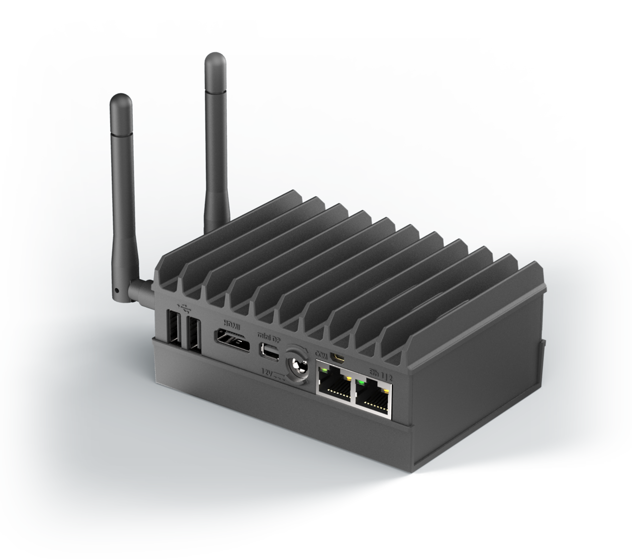
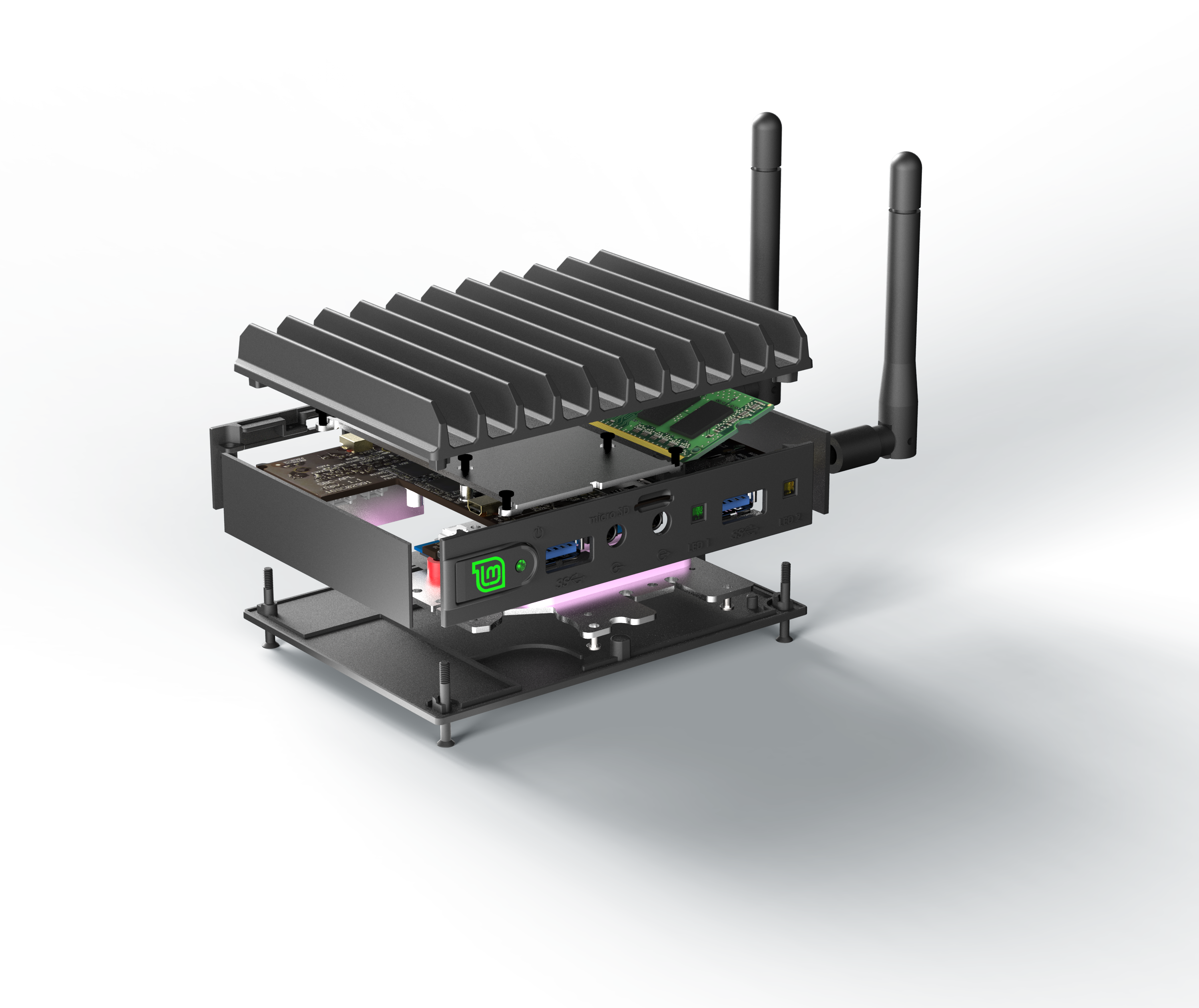
MintBox Mini 2 PC
The new MintBox Mini 2 comes with a new upgrade to the processor. It comes with a quad-core Apollo lake Intel Celeron J3455 SoC (System on Chip). This new upgrade gives it more power potential over the AMD A10-Micro 6700T of Mintbox Mini Pro and it is even 30 per cent faster. As usual, the MBM2 is modelled after Compulab’s Fitlet 2 mini PC (personal computer), and it comes with new FACET expansion cards for 2.5-inch HARD DISK DRIVE (HDDs), Power over Ethernet (PoE), CONTROLLER AREA NETWORK (CAN) bus and many more.
MintBox Mini 2 comes with the latest Linux Mint 19 “Tara” Cinnamon Edition distro operating system, and it offers Intel HD Graphics 500 and a 10W TDP (Thermal Design Power).
The MintBox Mini 2 is available in two main variants:
The MintBox Mini 2, and
the MintBox Mini 2 Pro.
The MintBox Mini2 is available for a cost of $299 and the pro version for $349. The ordinary Mini2 comes with a 4GB DDR3 RAM and a 64GB SSD for system storage and the Mini2 Pro comes with 8GB DDR3 RAM and higher storage of 120GB SSD. Of course, you can increase both system memory up to about 16GB RAM.
Other features include HDMI 1.4a and mini-DisplayPort, dual GbE ports, 2x USB 3.0 which are facing the front, two rear-facing USB 2.0, and a mini-RS232 port. It also comes with an Intel 8260 wireless chipset with WiFi 802.11ac, Bluetooth 4.2, a micro-SD slot, and dual 3.5mm audio jacks. Temperature range is -40°C to 85°C, there is a 7 to 20V DC input, and the dimensions are 112m by 84mm by 34mm.
MintBox Mini 2 Block Diagram
There are six optional FACET expansion cards which have been provided by Compulab for the MintBox Mini 2:
FC-POED — additional (third) GbE port with power via Power-over-Ethernet (PoE) and “preserve WiFi.”
FC-PCI or FC-CEM — 4G modem + WiFi + M.2 2280 SATA SSD
HDx —5-inch SATA HDD/SSD up to 15mm / 5TB
FC-USB — 4x additional USB ports (for 8x overall)
FC-SCG — RS232/RS485, GPIOs, and CANbus port
The two types of MintBox Mini 2 PCs are now available from Compulab and the Linux Mint project, and they come with a five-year warranty. Five per cent of all the revenues gathered to go to the Linux Mint project. If you are interested in purchasing the MintBox Mini 2 PCs, you now get it on the product page, and it is also expected that the product will be available on Amazon from August.
Singapore-based startup Kobol has successfully launched its open-spec “Helios4” NAS (network-attached storage) SBC and fanned system. In May 2017, Kobol tried to launch the open-spec Helios4 SBC and fan-equipped system for NAS on Kickstarter. Though a total of 337 backers helped to raise $74K for the Helios4, Kobol fell short of its $110K funding goal.
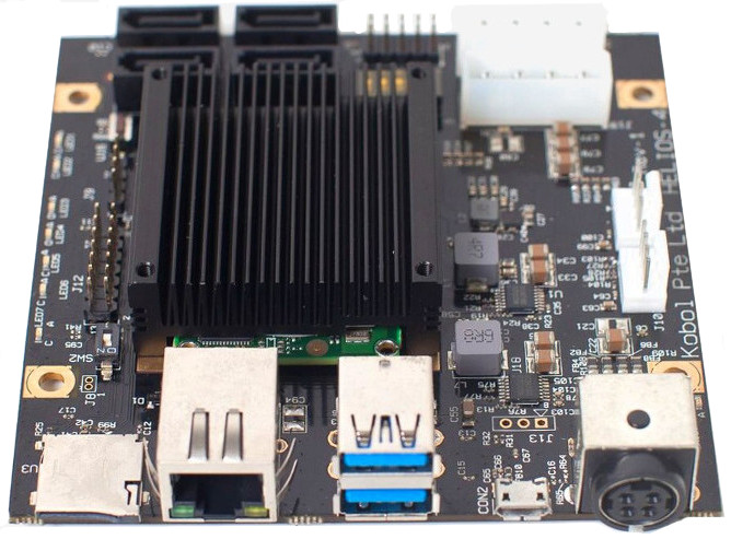
Kobol Helios4 mainboard
The Helios4 NAS SBC runs Debian on a Marvell Armada 388, a dual Cortex-A9, 1.6GHz SoC with cryptographic and XOR DMA engines with 2GB ECC RAM and offers 1x GbE, 2x USB 3.0, and 4x SATA 3.0 ports for up to 48TB. Kobol no longer offers the low “early bird prices” of the Kickstarter campaign, but pricing is otherwise the same as the standard 2GB RAM packages. The 1GB packages are discontinued. The Helios4 Basic Kit (SBC only) is available at $176.12 and a Full Kit with SBC, fans, and 4x SATA is available at $194.46. Both of the kits ship with 2GB of DDR3L ECC RAM.
The Armada 388 SoC and 2GB of error-correcting DDR3L are made available via a SolidRun MicroSoM A388. This Linux-ready module was first announced as the 38x-MicroSoM and is also referred to by Kobol as the A38x MicroSoM. Kobol’s new SBC sports with 4x SATA 3.0 ports, 4x SATA cables and 2x Molex interfaces “to dual SATA power cable”. The clever design lets the user connect up to 48TB storage. Also, Helios4 features 2x USB3.0 port and a full duplex GbE port. A microSD slot and a mini-USB-to-serial port for the console are too present. Other features incorporate I2C, GPIO, control panel, and PWM fan headers. A DC jack connects to 12V/8A adapter, and there are HDD power connectors and a reset button.
The company is now running its own funding campaign to manufacture a second 500-unit batch. So far, the Full Kit is half funded while the Basic Kit has drawn little interest. Kobol says that it will refund the money if the campaign doesn’t reach its 500-unit goal by Aug. 5. Shipments are due in October. The Helios4 SBC Basic Kit and Full Kit system are available for crowdfunding on Kobol’s website for $176.12 and $194.46, respectively. More information may be found on Kobol’s relaunch announcement, as well as the Basic Kit and Full Kit crowdfunding/shopping pages. There’s also a Helios4 wiki.
The Raspberry Pi 3 and other boards like the Asus Tinker Board are Single Board Computers (SBCs) that gives the user the full power of a computer without the need of any external parts. SBC offers a ready-to-use embedded development platform and helps to accelerate the time to market for a new product with mitigating risks. The Raspberry Compute Module 3, on the other hand, is a Computer on Module/System on Module that usually designed to be used in an embedded product.
Unlike SBCs that usually comes with fixed computing, resources, memory, peripherals, and I/O sections, CoM/SoM gives engineers and developers the full ability to customize their board as per the needs of the application. You can decide on what you want, the GPIO ports you need to extend out, or even the memory options. Another significant use of SoM is they are usually future proof, unlike SBCs.
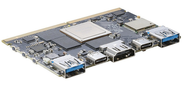
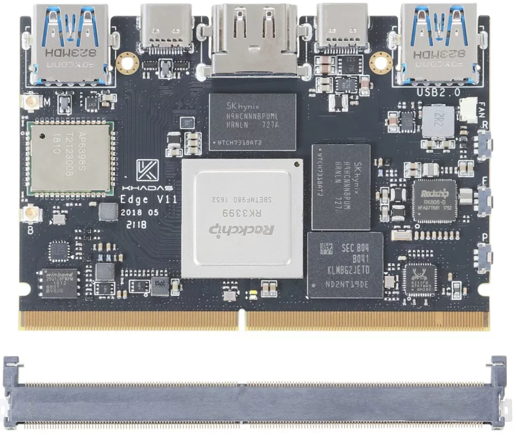
Khadas Edge
So what if we don’t have to choose between both worlds, get the smooth deployment of the SBCs plus the customization of the SoM without necessarily having to purchase 2 different boards. The Khadas Edge is an upcoming product that is going to make this realization possible.
The Khadas Edge board is a board that attempts to combine both worlds. A single standalone board and system on module powered by the Rockchip RK3399 SoC. It combines a USB receptacle and HDMI output as well as 314-pin MXM3 edge connector to connect to a Khadas Captain baseboard or any other custom compatible baseboard.
The Khadas Edge will be a different step from their usual Amlogic based SBC as found on the Khadas Vim and Khadas Vim2 SBC. It is powered by a hexa-core Rockchip RK3399 SoC carrying Big Cluster CPU; a Dual-core Cortex-A72 running at up to 1.8GHz, and a Little Cluster CPU; a quad-core Cortex-A53 running at up to 1.5GHz with a Mali T864 GPU.
The Khadas Edge is expected to come in three variants; the Basic, the Pro, and the Max. The Khadas Edge can plug into the Khadas Captain baseboard to act as a full standalone SBC.
Other features — 3x buttons; 2x LEDs; heatsink (TBC); optional Edge IO and Khadas Captain boards
Power — 5-20V DC input via USB Type-C, Pogo Pads, MXM3; 2-cell battery module
Weight — 25 gm
Dimensions — 82.0 x 57.5 x 5.7mm
Operating system — Android Oreo, Ubuntu 18.04, Debian 9.0, etc. with mainline Linux and U-Boot; support for TensorFlow and Android NN (Neural Networks API)
The board should ship with two Wi-Fi antennas and a heatsink. Operating systems support includes Android Oreo, Ubuntu 18.04, and Debian 9.0 with mainline Linux, as well as AI features such as TensorFlow, Android NN (Neural Networks API).
The Khadas Edge and Khadas Captain are expected to launch in a crowdfunding campaign in August, and more information should be available on the product page by then.
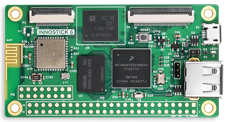
Shanghai Naxing Electronics (NXElec) has now entered to the NXP world with its miniature version of the new “Innostick 6”SBC. The 80 x 42mm footprint board features the low-power, i.MX6 ULL, a variation on the i.MX6 UltraLite (UL) that offers a single Cortex-A7 core which is clocked at 900MHz. Other i.MX6 ULL SBCs include MYIR’s 70 x 55mm MYS-6ULX and PolyVection’s open source VoltaStream Zero, an audio streaming SBC that features a similar footprint.
NXElec Innostick 6 SBC
The system is equipped with a variation of Yocto Project “Morty” based Linux stacks, one with X11 and one with Qtopia. Debian Stretch is also supported by this board. There is no evidence that this is an open source board. However, there’s a wiki on elinux.org and the company has a section in the forums at the PhpBB community site.
The Innostick 6 ships with 512MB DDR3L RAM and either 16GB or 32GB eMMC storage. There’s no Ethernet port available, but WiFi and Bluetooth are present. The only coastline ports are the USB 2.0 host and micro-USB OTG ports. The SBC is further equipped with a resistive touch-enabled LCD interface and a CSI Parallel camera interface. There are also 16- and 50-pin GPIO headers.
Specifications listed for the Innostick 6 include:
Processor: NXP i.MX6 ULL; 1x Cortex-A7 @ 900MHz
Memory & storage: 512MB DDR3L; 16GB or 32GB eMMC
Wireless: 802.11b/g/n with Bluetooth 4.0 (AP6212 module)
Display & camera:
24-bit RGB LCD interface with 4-wire resistive touch support
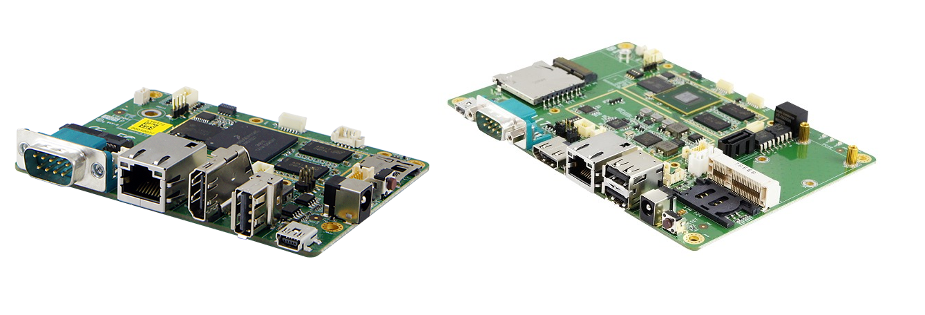
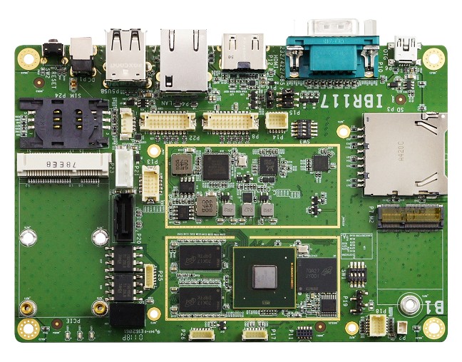
iBase, an industry leader in embedded solutions and services has now unveiled a new SBC that targets the ARM market. The new SBCs (Single Board Computer) launch will make a new shift for iBase from its traditional Intel-based SBC such as their recent Apollo Lake driven IB818. These new set of SBCs are called the Pico-ITX and are powered by NXP i.MX6 SoC.
IBR115 and IBR117
iBase launches the 2.5-inch Pico-ITX (IBR115) and 3.5-inch (IBR117) SBCs that both run Linux (ships with BSPs for Yocto Project 2.0) or Android and provides GPIO support just like other SBCs. At the core of the boards is the NXP i.MX 6 SoC. The i.MX 6 series of applications processors offer performance and scalable multicore platform including the single, dual, and quad-core families based on the Arm® Cortex® architecture. The IBR115 is powered by the NXP Cortex™-A9, i.MX 6 Dual-Lite 1GHz processor and the IBR117 is powered by the slightly higher NXP Cortex™-A9, i.MX 6 Dual 1GHz processor. The difference is very minimal though.
The IBR115 will be the first of its SBC to adopt the smaller Pico-ITX form factor measuring at about 100 x 72 mm also known as the 2.5-inch and the IBR117 measures about 147mm x 102mm called the 3.5-inch form factor.
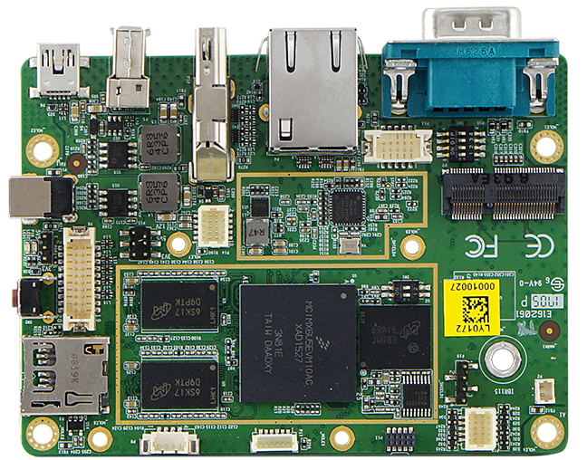
IBR115 SBC
The two products offer similarly identical features. They both provide display interface support like HDMI and LVDS, 1GB of DDR3 RAM, 4GB eMMC, a mini-USB OTG port, a USB 2.0 host port, USB headers, a GbE port, plus an optional WiFi/Bluetooth module that plugs into an M.2 E-Key (2230) slot, and SD slot. The IBR117 supplies a full-sized SD slot instead of the microSD slot on the IBR115, a dual LVDS interface as compared to the single LVDS interface on the IBR115.
IBR117
The SBCs do not lack in the GPIO department either. The IBR115 comes with the following expansion options:
3x Green LEDs (1x power, 1x wireless status, 1x programmable)
2x CAN Bus via 2×3 pin header
8x GPIO (2×5 pin header 1.0mm)
1x SATA connector & 4 pins wafer for the power, 5V/12V
They both offer operating temperature ranges ideal for the industries 0°C~ 60°C (32°F ~ 140°F) and an even larger range of -40°C ~85°C (-40°F ~ 185°F) with an optional heatsink.
Currently, no pricing or availability information has been provided for the IBR115 and IBR117 SBCs aside requesting for a private quote from iBase. More details about the SBCs are available on the IBR115 and IBR117 product pages.
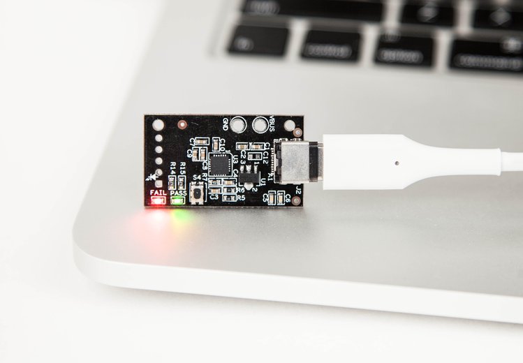
A small, open, affordable USB-C power adapter tester is live on crowdsupply.
We are quickly entering the age of USB Type-C. This “jack of all trades” port is appearing in more and more new electronic devices.
USB Type-C helps to reduce reliance on proprietary power adapters and USB cables; you can move to a single, robust, and compact solution that works on all devices. USB-C is quickly replacing various USB-B and USB-A connectors and cables with a standard that is meant to be “future-proof.”
As more and more of our devices will be using USB-C power adapters, it is essential that developers and manufacturers have an easy way to test their USB-C power adapters during development and manufacturing.
That’s where the USBCEE Tiny-PAT comes in – it’s the world’s smallest, fastest, easiest, and lowest cost USB-C power adapter tester.
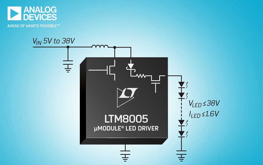
A DC/DC µModule regulator from Analog Devices is designed to drive LEDs. The Power by Linear LTM8005 regulator includes a DC/DC controller, power switch, Schottky diode and current sense resistor in a 9.0 x 11.25 x 2.22mm BGA package.
The LTM8005 operates from a 5.0 to 38V input voltage range and can deliver up to 1.6A of regulated current at an output voltage of up to 38V. An external inductor enables the LTM8005 to configure in different operation modes including boost, buck-boost, buck and SEPIC topologies, with a coupled inductor.
The high-reliability H-grade version guarantees operation from –40 to +150 degree C. The wide input voltage range and +150 degree C operation make this µModule LED driver suitable for use in automotive and industrial lighting applications.
The operating frequency is adjustable from 100kHz to 1MHz, while integral spread spectrum frequency modulation improves EMC performance, claims Analog Devices. LED brightness can be controlled by the analogue CTRL pin and by PWM dimming with a range up to 3,000:1. The LTM8005’s safety features include output disconnect short-circuit protection, open LED protection, programmable input current limit, as well as, input and output current reporting.
The E and I grades of the LTM8005 operate from –40 to +125 degree C.
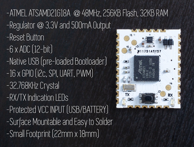
An easy to solder Arduino and CircuitPython compatible module meant for simplifying the creation of your own custom circuit boards. The project is live on kickstarter.
The SAMD HCC Module is an Arduino compatible, ready and easy to solder, surface mount programmable micro-controller module. Its purpose is to simplify the process of creating and building your own custom circuit boards without the need of worrying about soldering small fragile components, while still retaining all of the benefits of a tiny, lightweight, and low power micro-controller. Think of it as a way to bridge the gap between breadboard prototypes and full on “solder yourself” custom circuit boards. This is the simplified missing link. You use the module in combination with your custom circuit boards, to solder it directly to the board. No need for programming headers, power supplies, or FTDI chips.
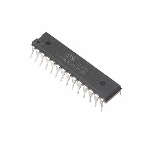
One of the downsides of using an Arduino board in projects is the fact that it comes with some other components which may not be needed after the code has been uploaded to the board. These peripherals consume a considerable amount of power which affects the overall power consumed by the project, thus increasing the rate at which the energy stored in batteries used for powering such project. This makes the Arduino boards not suitable for projects which are required to run on battery for long period of time like a weather monitoring station as there will be a need for constant battery change due to the high consumption rate of the device. One way to solve this problem while still retaining the “ease of use” that accompanies the Arduino platform is to use the ATMEGA328p microcontroller used on the Arduino Uno itself. By using this chip, we eliminate the power loss of other components that make up an Arduino board and thus the battery will last for longer time.
Low-Power Arduino Weather Monitoring Station – [Link]
One of the downsides of using an Arduino board in projects is the fact that it comes with some other components which may not be needed after the code has been uploaded to the board. These peripherals consume a considerable amount of power which affects the overall power consumed by the project, thus increasing the rate at which the energy stored in batteries used for powering such project. This makes the Arduino boards not suitable for projects which are required to run on battery for long period of time like a weather monitoring station as there will be a need for constant battery change due to the high consumption rate of the device. One way to solve this problem while still retaining the “ease of use” that accompanies the Arduino platform is to use the ATMEGA328p microcontroller used on the Arduino Uno itself. By using this chip, we eliminate the power loss of other components that make up an Arduino board and thus the battery will last for longer time.
Atmega328p microcontroller
The Atmega328p chip can be programmed in two main ways, assuming it has Arduino bootloader burned on the mcu.
Using an Arduino Uno
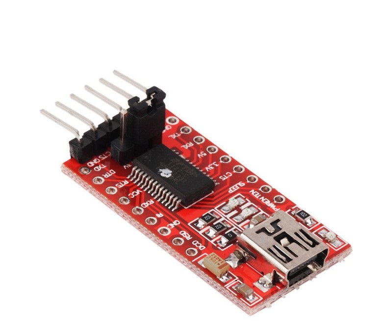
Using a USB to Serial/TTL Adapter
The first way of programming the chip is the easiest as all we need to do is insert the chip into the Arduino Uno, upload the code and move it from the Arduino to our project when ready. The second option is used when there is no Arduino board. A USB to Serial adapter (an example is shown below) is connected directly to the microcontroller to program it via the Arduino IDE.
USB to Serial/TTL Adapter
To program the Atmega328p using any of the methods mentioned above, it is important that the microcontroller is flashed with the Arduino bootloader. The Arduino bootloader is the code that facilitates programming the Atmeg328p chip’s memory using Arduino IDE. A detailed tutorial on how the Arduino bootloader works and how the Atmega328p can be flashed with it can be found here.
To demonstrate how to use the Atmeg328p microcontroller in projects to achieve low power consumption, we will make an upgrade to one of our Arduino weather stations project which was built to last a month initially running on AA batteries. Now we are going to make it last a year using the Atmeg328p microcontroller.
The weather station comprises by the BH1750, BMP180, DHT22 and Nokia 5110 LCD display. The BH1750 sensor is used to measure the light intensity, BMP180 to measure barometric pressure, DHT22 to measure temperature and humidity and all the measured data will be displayed on a Nokia 5110 LCD display.
Required Components
The following components are needed to build this project;
As usual, all the components listed above can be purchased via the link attached to them.
Schematics
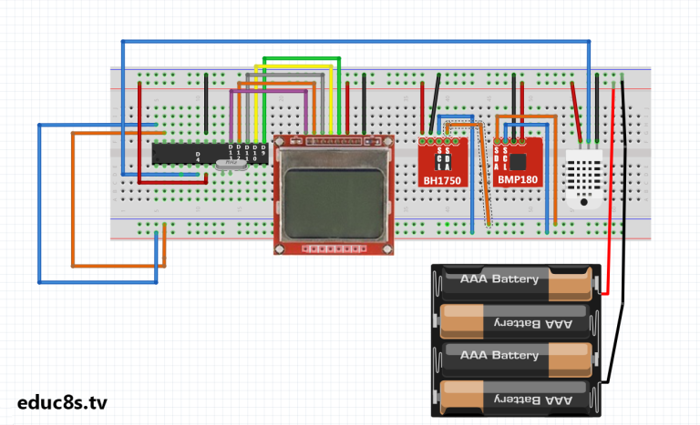
Connect the components as shown in the schematics below.
Schematics
The schematics start with the connection of the crystal oscillator to pin x1 and x2 of the microcontroller after which, each of the other components are connected. The connections between the other components and the Atmeg328p are shown below as a pin map.
The DH1750 is an I2C based sensor, this is why it is connected to the same line as the BMP180 as they are both I2C based sensors.
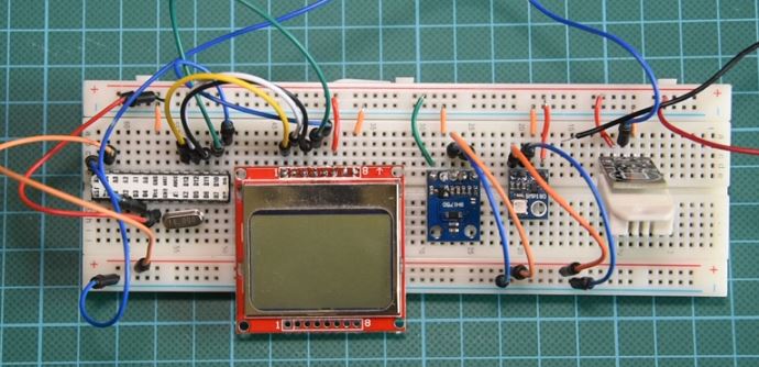
After connecting the components on the breadboard, the setup should look like the image below.
Schematics Implemented on a prototyping board
Code
In hardware design and development, power management is done both from the hardware end by choosing low power components and from the software end by powering down internal microcontroller peripherals when they are not needed and other things like adjusting the voltage and frequency to ensure they meet the standard requirements. To reduce power consumption from the software (firmware) side of the device, we will use the Arduino low-power.h library. This library allows us to shut down internal peripherals of the microcontroller using time or via the use of interrupts.
Asides the low-power.h library, the Nokia 5110 LCD library, and library for the BMP180, BH1750 and DHT 22 will be used to easily interface the sensors with the Arduino.
To briefly explain the code for this project, we start by including all the libraries that will be needed as mentioned above.
//Written by Nick Koumaris
//info@educ8s.tv
//educ8s.tv
#include <BH1750.h>
#include "DHT.h"
#include <SFE_BMP180.h>
#include <Wire.h>
#include <LCD5110_Graph.h>
#include "LowPower.h"
Next, we specify the Arduino equivalent of the pins of the atmega328p to which the DHT sensor is connected as arguments after which we create an instance of the DHT library specifying that we are using the DHT22.
#define DHTPIN 4

#define DHTTYPE DHT22
Next, we create an object of the LCD class with the Arduino equivalent pins of atmega328p to which the LCD is connected as arguments after which we also create an object of the BMP180 class. With this done we then create some fonts to use for the display of data on the LCD.
The void loop() function is quite simple. we start by reading the light intensity, if the light intensity is above 30 lumens indicating daytime, we take the readings from other sensors and display them on the LCD. Using the low power library the function sleepfortwominutes() was created. This function shuts down all the hardware peripherals after a reading has been obtained preserving the battery life of the system setup.
The complete code for the project is available for download under the section towards the end of this page.
Demo
Insert the Atmega328P microcontroller into an Arduino and upload the code. After uploading the code, remove the microcontroller and insert it correctly into the circuit on the breadboard.
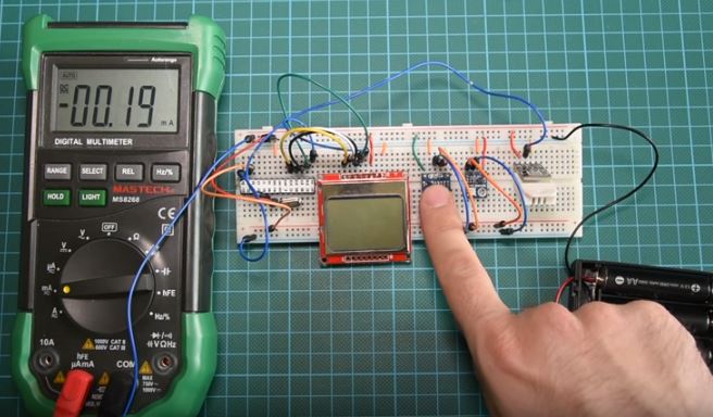
While we can not wait for a year to confirm that this project will have a battery life longer than 1 year, we can measure the system’s current consumption and use that data to estimate how long a battery will last.
In sleep mode with the screen off, the current draw of the system was o.19mA
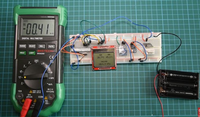
With the LCD on and the microcontroller in sleep mode, the current draw was 0.41 mA.
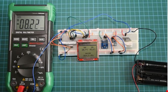
When the system is fully powered, with the microcontroller reading data from sensors, the current draw is 8.22mA
Using the excel sheet attached alongside the code and schematics under the download section, we can see that the system would last for a year running on batteries due to the amount of energy we save by occasionally putting the microcontroller to sleep.
That’s it for this tutorial guys, thanks for taking time to read through. Feel free to drop whatever questions you might have regarding this project under the comment section. I will do my best to provide answers.
The video tutorial for this project is located here.