Low-Power Arduino Weather Monitoring Station

Introduction

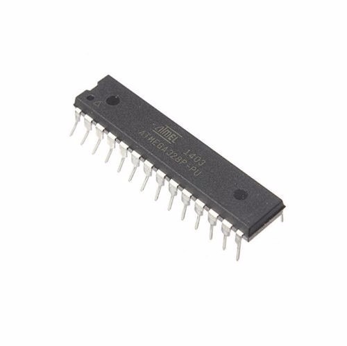
One of the downsides of using an Arduino board in projects is the fact that it comes with some other components which may not be needed after the code has been uploaded to the board. These peripherals consume a considerable amount of power which affects the overall power consumed by the project, thus increasing the rate at which the energy stored in batteries used for powering such project. This makes the Arduino boards not suitable for projects which are required to run on battery for long period of time like a weather monitoring station as there will be a need for constant battery change due to the high consumption rate of the device. One way to solve this problem while still retaining the “ease of use” that accompanies the Arduino platform is to use the ATMEGA328p microcontroller used on the Arduino Uno itself.  By using this chip, we eliminate the power loss of other components that make up an Arduino board and thus the battery will last for longer time.

Atmega328p microcontroller

The Atmega328p chip can be programmed in two main ways, assuming it has Arduino bootloader burned on the mcu.

  1. Using an Arduino Uno
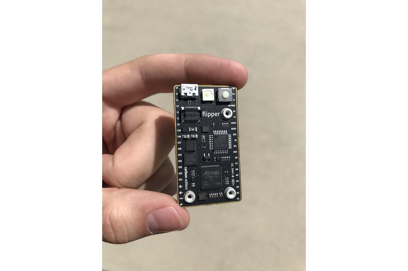
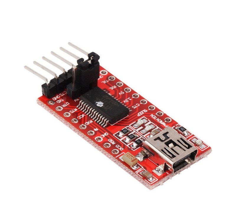
  2. Using a USB to Serial/TTL Adapter

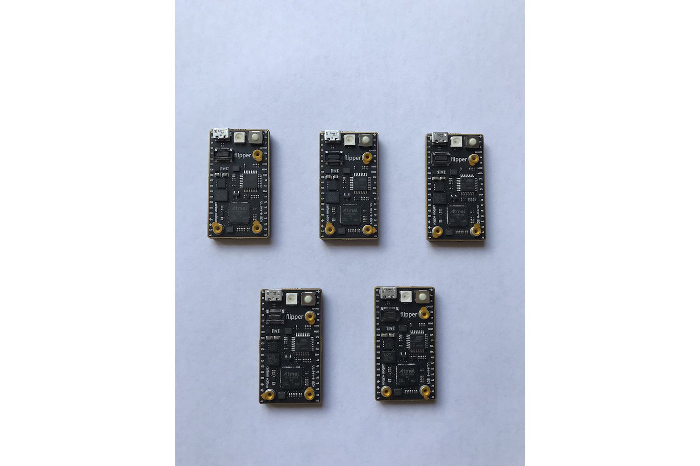
The first way of programming the chip is the easiest as all we need to do is insert the chip into the Arduino Uno, upload the code and move it from the Arduino to our project when ready. The second option is used when there is no Arduino board. A USB to Serial adapter (an example is shown below) is connected directly to the microcontroller to program it via the Arduino IDE.

USB to Serial/TTL Adapter

To program the Atmega328p using any of the methods mentioned above, it is important that the microcontroller is flashed with the Arduino bootloader. The Arduino bootloader is the code that facilitates  programming the Atmeg328p chip’s memory using Arduino IDE. A detailed tutorial on how the Arduino bootloader works and how the Atmega328p can be flashed with it can be found here.

To demonstrate how to use the Atmeg328p microcontroller in projects to achieve low power consumption, we will make an upgrade to one of our Arduino weather stations project which was built to last a month initially running on AA batteries. Now we are going to make it last a year using the Atmeg328p microcontroller.

The weather station comprises by the BH1750, BMP180, DHT22 and Nokia 5110 LCD display. The BH1750 sensor is used to measure the light intensity,  BMP180 to measure barometric pressure, DHT22 to measure temperature and humidity and all the measured data will be displayed on a Nokia 5110 LCD display.

Required Components

The following components are needed to build this project;

  1.  ATMEGA328
  2. 16Mhz Crystal
  3. NOKIA 5110 DISPLAY
  4. BMP180
  5. BH1750
  6. DHT22
  7. Large Breadboard
  8. FTDI programmer
  9. Jumper wires
  10. Battery Case
  11. Multimeter
  12. Wires
  13. Cheap Arduino Uno
  14. Batteries

As usual, all the components listed above can be purchased via the link attached to them.


Schematics

Connect the components as shown in the schematics below.

Schematics

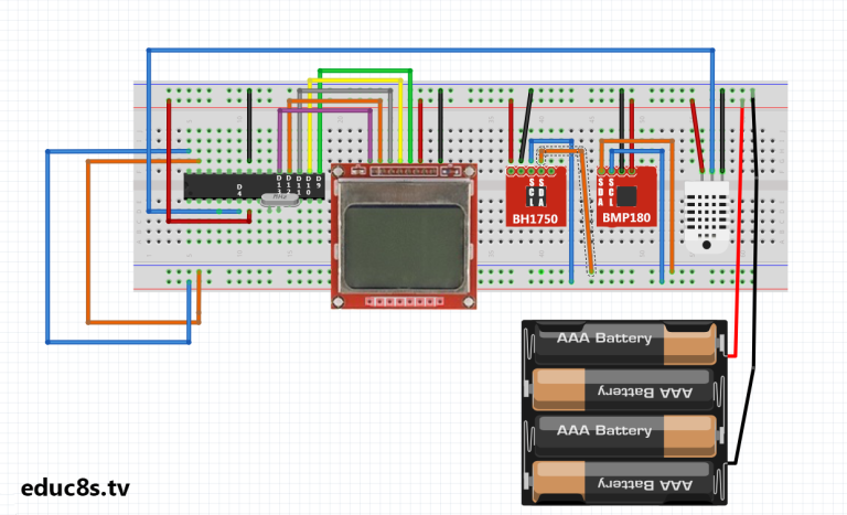
The schematics start with the connection of the crystal oscillator to pin x1 and x2 of the microcontroller after which, each of the other components are connected.  The connections between the other components and the Atmeg328p are shown below as a pin map.

Nokia 5110 – Atmega328p

Pin 1(RST) – D13
Pin 2(CE) – D12
Pin 3(DC) – D11
Pin 4(DIN) – D10
Pin 5(CLK) – D9
Pin 6(VCC) - VCC
Pin 7(LIGHT) - GND
Pin 8(GND) - GND

DHT22 – Atmeg328p

VCC - 5v
GND - GND
Signal - D4

DH1750 – Atmeg238p

SDA - A4
SCL - A5
GND - GND
VCC - 5V


BMP180 – Atemg328p

VCC - 5V
GND - GND
SDA - A4
SCL - A5


The DH1750 is an I2C based sensor, this is why it is connected to the same line as the BMP180 as they are both I2C based sensors.

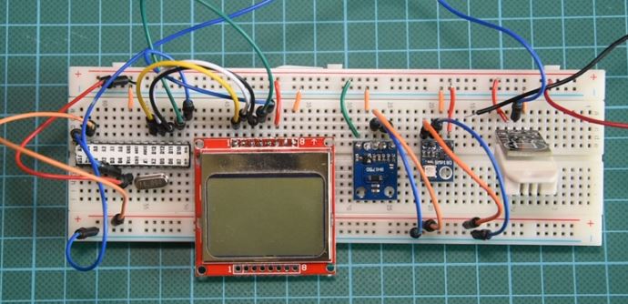
After connecting the components on the breadboard, the setup should look like the image below.

Schematics Implemented on a prototyping board

Code

In hardware design and development, power management is done both from the hardware end by choosing low power components and from the software end by powering down internal microcontroller peripherals when they are not needed and other things like adjusting the voltage and frequency to ensure they meet the standard requirements. To reduce power consumption from the software (firmware) side of the device, we will use the Arduino low-power.h library. This library allows us to shut down internal peripherals of the microcontroller using time or via the use of interrupts.

Asides the low-power.h library, the Nokia 5110 LCD library, and library for the BMP180, BH1750 and DHT 22 will be used to easily interface the sensors with the Arduino.

To briefly explain the code for this project, we start by including all the libraries that will be needed as mentioned above.

//Written by Nick Koumaris 
//info@educ8s.tv 
//educ8s.tv
#include <BH1750.h>
#include "DHT.h"
#include <SFE_BMP180.h>
#include <Wire.h>
#include <LCD5110_Graph.h>
#include "LowPower.h"

Next, we specify the Arduino equivalent of the pins of the atmega328p to which the DHT sensor is connected as arguments after which we create an instance of the DHT library specifying that we are using the DHT22.

#define DHTPIN 4  

#define DHTTYPE DHT22

Next, we create an object of the LCD class with the Arduino equivalent pins of atmega328p to which the LCD is connected as arguments after which we also create an object of the BMP180 class. With this done we then create some fonts to use for the display of data on the LCD.

LCD5110 lcd(9,10,11,13,12);

SFE_BMP180 pressure;
extern unsigned char SmallFont[];
extern unsigned char TinyFont[]

Up next is the void setup function under which we initialize the LCD, the light intensity sensor, and the pressure sensor.

void setup(void) {
  initLCD();
  lightMeter.begin();
  pressure.begin();
}

The void loop() function is quite simple. we start by reading the light intensity, if the light intensity is above 30 lumens indicating daytime, we take the readings from other sensors and display them on the LCD.  Using the low power library the function sleepfortwominutes() was created. This function shuts down all the hardware peripherals after a reading has been obtained preserving the battery life of the system setup.

void loop() {

 float humidity, pressure; 
 readLight();
 if(lightIntensity>30)
 {
 lcd.disableSleep();
 dht.begin();
 delay(400);
 humidity = dht.readHumidity();
 temperature = dht.readTemperature();
 pressure = readPressure();
 
 lcd.clrScr(); 
 char tempF[6]; 
 char humF[6];
 char pressF[7];
 
 dtostrf(temperature, 5, 1, tempF);
 dtostrf(humidity, 5, 1, humF);
 dtostrf(pressure, 5, 1, pressF);

  //Print UI
  lcd.setFont(TinyFont);
  lcd.print("TEMP",LEFT+17,0);
  lcd.print("HUM",LEFT+62,0);
  lcd.print("PRESSURE",CENTER,30);

  lcd.setFont(SmallFont);
  //Printing Temperature
  lcd.print(tempF,LEFT,10);
  lcd.print("~C",LEFT+30,10);

  //Printing Humidity
  lcd.print(humF,LEFT+45,10);
  lcd.print("%",RIGHT,10);

  //Printing Pressure
  lcd.print(pressF,12,40);
  lcd.print(" hPa",48,40);

  lcd.update();

  sleepForTwoMinutes();
 }else
 {
    lcd.enableSleep();
    sleepForTwoMinutes();
 }
}


The complete code for the project is available for download under the section towards the end of this page.

Demo

Insert the Atmega328P microcontroller into an Arduino and upload the code. After uploading the code, remove the microcontroller and insert it correctly into the circuit on the breadboard.

While we can not wait for a year to confirm that this project will have a battery life longer than 1 year, we can measure the system’s current consumption and use that data to estimate how long a battery will last.

In sleep mode with the screen off, the current draw of the system was o.19mA

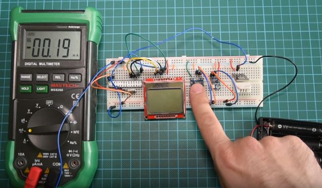
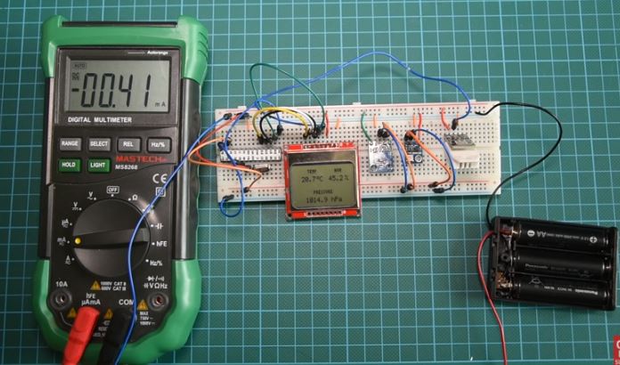
With the LCD on and the microcontroller in sleep mode, the current draw was 0.41 mA.


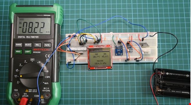
When the system is fully powered, with the microcontroller reading data from sensors, the current draw is 8.22mA

Using the excel sheet attached alongside the code and schematics under the download section, we can see that the system would last for a year running on batteries due to the amount of energy we save by occasionally putting the microcontroller to sleep.

That’s it for this tutorial guys, thanks for taking time to read through. Feel free to drop whatever questions you might have regarding this project under the comment section. I will do my best to provide answers.

The video tutorial for this project is located here.

RasPiO Night Light – gently lights your way in the dark

See where to go at night without fully waking up. Only on as needed. Customisable RGB LED lighting. Ideal: hall, landing, garage, shed.

RasPiO Night Light is motion-activated RGB light that lights your way in the dark. It’s a lovely build-it-yourself kit designed to be gorgeous to look at and fun to build, use and tweak.

  • enjoy making it
  • enjoy tweaking it to your requirements
  • enjoy being greeted by it when you walk past in the dark

RasPiO Night Light – gently lights your way in the dark – [Link]

96-layer BiCS FLASH prototype from Toshiba uses QLC technology

Toshiba Memory Europe has developed a prototype sample of a 96-layer BiCS FLASH, memory device using its proprietary 3D flash quad level cell (QLC) technology, claimed to boost single-chip memory capacity to the highest level yet achieved.

QLC technology increases the bit count for data per memory cell from three to four, “significantly expanding capacity” says Toshiba. The memory devices achieves the industry’s maximum capacity of 1.33Tbits for a single chip. It was jointly developed by Toshiba Memory Europe with Western Digital.

The memory also realises 2.66Tbytes in a single package by using a 16-chip stacked architecture. This is claimed to be an unparalleled capacity in a memory device, and is designed for the anticipated volumes of data generated by mobile terminals, as well as the spread of SNS, the progress in the IoT and the demand for analysing and using that data in real time. All of which are expected to increase dramatically. Data volumes will also require even faster HDDs and larger capacity storage and such QLC-based products, using the 96-layer process, will contribute to the solution, believes Toshiba Memory Europe.

Toshiba Memory will start to deliver samples to SSD and SSD controller manufacturers for evaluation from the beginning of September and expects to start mass production in 2019.

A packaged prototype of the new device will be exhibited at the 2018 Flash Memory Summit in Santa Clara, California, USA from August 6th to 9th.

Toshiba Memory Europe is the European business of Toshiba Memory, and offers a broad product line of flash memory products, including SD cards, USB flash drives, and embedded memory components, in addition to solid state drives (SSDs). Company offices are in Germany, France, Spain, Sweden and the United Kingdom.

http://www.toshiba-memory.com

Introduction to the silicon photomultiplier (SiPM)

App note from ON Semiconductors about SiPM sensors, explaining the working principle and primary performance parameters.

The Silicon Photomultiplier (SiPM) is a sensor that addresses the challenge of sensing, timing and quantifying low-light signals down to the single-photon level. Traditionally the province of the Photomultiplier Tube (PMT), the Silicon Photomultiplier now offers a highly attractive alternative that combines the low-light detection capabilities of the PMT while offering all the benefits of a solid-state sensor. The SiPM features low-voltage operation, insensitivity to magnetic fields, mechanical robustness and excellent uniformity of response. Due to these traits, the SensL® SiPM has rapidly gained a proven performance in the fields of medical imaging, hazard and threat detection, biophotonics, high energy physics and LiDAR.

Introduction to the silicon photomultiplier (SiPM) – [Link]

Flipper Allows You Build Embbeded Applications with Any Programming Language

With the rise of Arduino, Raspberry Pi and others; embedded platform has been known to be programmed with a relatively few languages. Languages like C and C++ has been the tradition  for embedded platforms, and others like Python and maybe Javascript are beginning to see some limelight with the advent of the Rasberry Pi SBC and increase the open hardware movement.

The quest to allow programming hardware with several programming languages has been one daring challenge some makers and designers have taken upon themselves. The likes of the Johnny-Five framework and Espruino have given programmers extra options by providing options for programming the Arduino with Javascript and this will not end here. Flipper is one of such platforms that offers much more, is an embedded development board that can be controlled from any programming language.

Flipper Embedded Platform

Flipper is a unique embedded development platform that enables makers to create their own applications using whatever language they want and interestingly open-source with a growing community. Flipper completely rethinks the traditional embedded programming model, you can either build with the flipper board or interact flipper with other awesome hardware.

Flipper can be thought of as a hardware that acts like a software library, so all you just have to do now is call the library in your existing language project. According to Flipper’s designer George Morgan,

“I wanted to create an embedded development platform that could be used from any language, on any platform, and from the tools familiar to the user of the platform.”

The Flipper: Carbon board is powered by an Atmel ATSAM4S16B Arm Cortex-M4 SoC, which featured 1MB of Flash Memory, 128KB of SRAM and it allows up to 8Mb of external Flash storage. Just like every other board, it provides support for up to 32 GPIO, I2C, SPI, USART, ADC and a 8-bit DAC. It comes with one ATMega32U2 that handles the code uploading from USB to the main MCU.

The board is not totally 5V tolerant, most of the pins are only 3.3v compatible and any 5V passed through those might likely damage the board.

Flipper development board is designed to interact with a host device like a PC, a powerful SBC (Single Board Computer), and others. This strategy allows most of the heavy work to be done on the host device and then passed off to the embedded system. The Flipper board can be controlled in three main ways:

  • Programmed directly like the way we have seen on Arduino and the code runs directly on the hardware.
  • Programmed indirectly from a Host device, where the code runs on a PC for example and the information are sent in real time to the board.
  • Combining both options; in this case, some codes run directly on the board while others on the host.
Flipper hardware is in a slim form factor. It is compatible with breadboards and off-the breadboard, unlike traditionally embedded boards that makes one select one.

The possibility of programming with several languages is possible due to the Flipper API. The MCUs on the board come pre-installed with a custom real-time operating system called Osmium that enables the device to talk to a variety of higher-level libraries written in a variety of programming languages. These libraries contain API that can control the device’s hardware peripherals. For example, if you’re writing an iOS or macOS app, you can simply drag and drop the .framework into your Xcode project and get started.

Flipper is still under development and already has bindings for the following languages:

  • C/C++
  • Objective-C/Swift
  • Rust
  • Python
  • Java
  • Javascript
  • Haskel

Flipper is special because it lets anyone control devices in the real world from applications written in any programming language, on any platform, with absolutely zero headache. Developers simply drag and drop our software library into their applications and start hacking. Everything works right out of the box using tools the developer is already familiar with. There is no need to learn how to use a new IDE, no need to learn a new programming language, and no need to focus on what doesn’t matter.

The Flipper board is available for purchase on tinder at a price of $49.49. More information about the Flipper platform is available on their Github page and the team behind the flipper is also looking for more contributions.

So irrespective of what hardware you want to build, the chances of building it with any language of your choice is now possible with the Flipper platform.

Node Mini Server – A Server For The Quest of A Decentralized Internet

The quest for a decentralised web is something that is gaining more ground in the lights of data theft, privacy concerns, and others. The internet as we all know is now becoming monopolised as the big corporations are leveraging business, startups, users, developers and others to use their centralised platforms while killing out other competitors.

Tim Berners-Lee who created the worldwide web initially design it to be a decentralised platform where anyone can publish a website and easily push contents and links to other sites. But with the eruption of the big companies like Amazon, Facebook, Google, Microsoft, and others the decentralised web has become a centralised one.

So the question is this – Is a life less dependent on cloud giants possible?

Launching a decentralised internet involves preparing down the infrastructure that will power it.

The Node Mini Server

This infrastructure will have to be in a way the corporations won’t control users data and not be centralised in one location. One way people can do about it is to dedicate there personal devices like a computer as a server among many others. Of course, this method might work, but it will be expensive to manage, and this is where the likes of Node Mini Server come into play.

The Node Mini Server is meant to be a computer based around the popular Raspberry Pi 3 single board computer designed to act as the hardware infrastructure for the decentralised web.

Ever since the first Raspberry Pi was launched, the advent and performance of single board computers have heavily improved. They reached to a point where they are small enough, about the size of a credit card, very cheap as compared to similar computers, and still carry a substantial power and are very flexible regarding add-ons. Taking these into consideration might make SBCs the ideal infrastructure for the decentralised age.

The Node Mini Server is an open source platform that takes readily available SBCs and hopefully makes them suitable as underlying physical infrastructure for the decentralised web. The Mini Server, at its core, is the Raspberry Pi 3 B+ with some improved and custom arts. Even though the Mini Server was built around the Raspberry Pi, it is expected to work on similar like the Asus Tinker Board, ODroid-C2 and other powerful Pi SBCs.

The Mini Server is made up of a 3D printed case and users can decide to 3D print their own design from any 3D printer available. The Mini server is designed in such to put all the ports all in one side. The ports are now located on the back; this includes the micro SD slot which has been extended from the default bottom, an HDMI port, and an interesting SATA adapter that will allow attaching a standard 2.5inch laptop drive which should be able to give up to 3TB of possible storage options. The Node Mini server casing provides a way to slot in the hardware onto the device. Due to the extra parts added to the device, the Mini server requires a quality 3A power supply to power all the components.

The Node Mini Server is believed to still be under development and no information is available about the software stack. The quest for a decentralised web is a promising prospect and with the likes of the node mini server, this reality is not far-fetched.

TTGO Micro-32 is a Module for ESP32-PICO-D4 SiP

The ESP32-PICO-D4 is a new variant of the known ESP32 SoC released by Espressif Systems. The PICO variant module measures around 13x19mm and it is designed as a system-in-package unlike the SoC styled ESP32, and comes with an ESP32 dual-core processor, a 4MB SPI flash, a crystal oscillator and come other accompanying components.

The ESP32-PICO-D4 SIP is designed for applications that are space conscious and looking to have less external components as possible. Applications like wearables, IoT devices, sensors, and battery operated devices will highly benefit from using this ESP32 variant, and it comes with the general functionality of the ESPP32 with network connectivity like WiFi and Bluetooth present.

Ever since the ESP32-PICO-D4 SIP was launched about a year ago, there has been little or no availability of a compact size module for use. The TTGO Micro-32 is a module based around the ESP32-PICO-D4 SIP with the hope of bringing more limelight to the ESP32 package.

The TTGO Module is a very compact module that can be used at the core of most ESP32 embedded applications, and it measures just about 19.2 x 13.3 mm which is about 45% smaller than the ESP32-WROOM-32 module.

Below are some of the TTGO Micro-32 module specifications:

  • SiP – Espressif Systems ESP32-PICO-D4 based on the ESP32 dual-core processor
  • Memory – 4MB SPI Flash
  • Connectivity –
    • Bluetooth 4.2 LE
    • 802.11 b/g/n WiFi up to 150 Mbps with chip antenna and u.FL (IPEX) connector
  • Power Voltage – 3.3DC Volts
  • Dimensions – 19.2 x 13.3 mm

The module is expected to be software compatible with the ESP-WROOM-32, and it doesn’t have any specific software attached to it. The TTGO Micro32 module is available for purchase on Banggood at a price of about $7. A similar TTGO Micro-32 module is available on Aliexpress for a lesser price of about $4.7.

Tiny Machine-Code Monitor

This project is a machine-code monitor that you program from a hexadecimal keypad using a simplified instruction set. by David Johnson-Davies

It’s a good project for learning about the fundamentals of machine code, and will also appeal to people who like programming challenges. The simplified machine code, called MINIL, is designed to be easy to learn and understand. It’s similar to the Little Minion Computer [1] used in some universities to teach students about machine code. The same method could be used to emulate other simple processors, such as the SC/MP, 6800, 8080, or 6502.

Tiny Machine-Code Monitor – [Link]

Virtual Helium Atom with Virtual Breadboard Infinity-Shield

How to connect the Helium Arduino stack with the Google IoT Core Channel using the Infinity-Shield mixed reality hardware emulator for VBB. by James Caska:

I have been developing Virtual Breadboard since 1999. It’s a fun way to learn about microcontrollers in a virtual sandbox and since I added the Arduino it’s been quite popular.

For several years now I have been working on ‘breaking out’ of the sandbox to mix virtual and real components together. These days there is a word for this – mixed reality.

Mixed reality addresses important limitations of the Virtual Breadboard sandbox and at the same time opens amazing up new possibilities of it’s own.

Virtual Helium Atom with Virtual Breadboard Infinity-Shield – [Link]

VIA Snapdragon 820 Based SOM now compatible with Linux

VIA Technologies known for its array of embedded boards and solutions has announced the release of a Linux Board Support Package (BSP) based on the Yocto 2.0.3 for the VIA SOM-9×20 module.

The VIA SOM 9×20 module was custom designed and meant for the Android platform and so migrating to a Linux framework was something that was inevitable and less tedious to achieve as compared to migrating to a different framework.

According to the Richard Brown, the Vice-president of International Marketing at VIA, he says that –

The release of the Linux BSP gives our customers an additional option for the development of Edge AI systems and devices powered by the Qualcomm® Snapdragon™ 820E Embedded Platform

The Linux BSP is expected to provide features like:

  • Supports UFS boot
  • Supports HDMI display
  • Supports AUO MIPI capacitive touch panels through the USB interface
  • AUO 10.1” B101UAN01.7 (1920×1200)
  • Supports COM as debug port
  • Supports two Gigabit Ethernet
  • Supports Mic-in and stereo 2W speaker
  • Supports built-in Wi-Fi 802.11 a/b/g/n/ac, Bluetooth 4.1, and GPS
  • Supports MIPI CSI camera OV13850

The VIA SOM 9×20 module is one of those modules you can’t afford to pass you by. At the heart of the module is the powerful Qualcomm Snapdragon 820E embedded platform, the high performance embedded platform designed to power the next generation of mobile devices and applications with low power consumption, and an array of possible connectivity.


The SOM 9×20 module measures at about 82 x 45mm in a SODIMM styled form factor. It features four Cortex-A72-like cores Kryo cores: two at 2.2GHz and two at 1.6GHz. The SoC is boosted with an integrated Adreno 530 GPU at 624MHz, Hexagon 680 DSP, and 14-bit Spectra ISP. The module ships with an inbuilt 64GB eMMC Flash memory, 4GB LPDDR4 in a POP package, rich I/O and display expansion options through its MXM 3.0 314-pin connector.

It supports USB 3.0, USB 2.0, HDMI 2.0, SDIO, PCIe, MIPI CSI, MIPI DSI, and multi-function pins for UART, I2C, SPI, and GPIO through the MXM connector. Other possibilities include interfaces for  MIPI-CSI and LCD touchscreen, dual speakers, and a mini-PCIe slot.

VIA also announced a $569 price for the evaluation kit package, which combines the Snapdragon 820 based module with its SOMDB2 Carrier Board. In order to simplify the design, testing, and deployment of intelligent Edge AI applications, VIA is making the SOM 9X20 module to be available as part of its Edge AI Developer Kit, which features a SOMDB2 Carrier Board and optional 13MP camera module that is optimized for intelligent real-time video capture, processing, and edge analysis.

The kit is available in two configurations from the VIA Embedded online store at:

  • VIA SOM-9X20 SOM Module and SOMDB2 Carrier Board with 13MP CMOS Camera Module (COB 1/3.06” 4224×3136 pixels): US$629 plus shipping
  • VIA SOM-9X20 SOM Module and SOMDB2 Carrier Board: US$569 plus shipping
  • Optional 10.1” MIPI LCD touch panel: US$179 plus shipping.

The Linux BSP for the VIA SOM 9X20 module is available now, and also an upgraded android 8.0 is available as well. More information about the product is available on the product page.

TOP PCB Companies