ESP32 with multiple DS18B20 temperature sensors

Guide to ESP32 with multiple DS18B20 temperature sensors from Random Nerd Tutorials:

This guide shows how to read temperature from multiple DS18B20 temperature sensors with the ESP32 using Arduino IDE. We’ll show you how to wire the sensors on the same data bus to the ESP32, install the needed libraries, and a sketch example you can use in your own projects. This tutorial is also compatible with the ESP8266 and the Arduino boards.

ESP32 with multiple DS18B20 temperature sensors – [Link]

All the Power of a Mini-ITX SBC on a 4” Board – the AAEON EPIC-KBS8

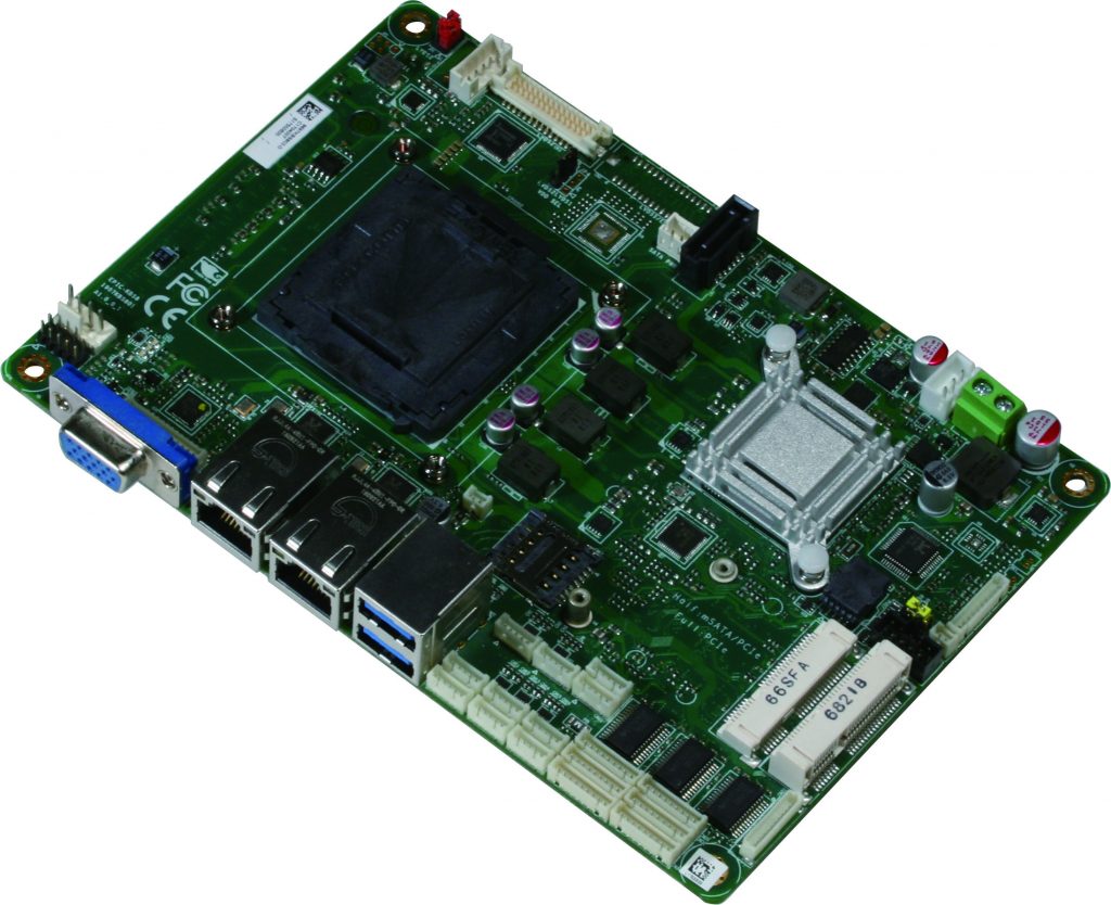
(Taipei, Taiwan – July 10, 2018) – AAEON, a global leader in industrial computing, releases the EPIC-KBS8, a powerful and expandable embedded controller purpose-built for retail and fintech applications.

The EPIC-KBS8 features a 6th/7th Generation Intel® Core™ i socket-type processor and up to 16GB DDR4 SODIMM memory. With other manufacturers only offering this level of computing power on larger, Mini-ITX boards, the EPIC-KBS8 represents a clear upgrade on competing products.

Modern retail solutions might include a camera, barcode scanner, cash register, scale, and even a fingerprint detector. To accommodate all these peripherals – and possible future technologies – the EPIC-KBS8 has two USB3.0 ports, up to ten internal USB2.0 connectors, and six COM connectors. The board also features possible dual LVDS support and the option of an eDP connection.

With its pair of LAN ports, the EPIC-KBS8 is also already being used as a powerful wireless Internet station, and its 0oC~60oC operating temperature range means it can be reliably used in the field. SATA, mSATA, and MiniCard slots provide multiple expansion slots, and the board’s CPU socket enables users to quickly and easily upgrade their processor whenever they want.

“Putting fast, socket-type processors on an EPIC board will give our customers a huge advantage,” said Alicia Wang, AAEON embedded computing division product manager. “Not only does the EPIC form factor’s smaller size make it cheaper to produce, but 4” boards can also be used in systems that Mini-ITX SBCs are just too bulky for.”

ESP8266 LED Matrix Clock

Simple LED matrix Clock based on the popular ESP8266 with Real Time Clock module and time synchronization over WiFi from an NTP server.

One note on the RTC module, apparently it also has the ability to charge the battery, however that’s not a good idea when using a CR2032. One possible solution would be to cut the trace marked on the image in order to disable the charging part of the circuit.

ESP8266 LED Matrix Clock – [Link]

Cellular IoT with Blynk & Hologram

Use a $9 GSM module & the Hologram network to remotely control any Arduino with Blynk App.

Blynk is an awesome tool that allows you to build drag and drop apps for controlling hardware remotely! Its perfect for quickly creating useful IoT projects. This tutorial will run you through setting up Blynk for cellular control using an Arduino and a $9 GSM board.

Hologram.io is a cellular network provider perfect for makers. At $0.60 /mo plus $0.40 per mb, you’ll have plenty of data for most IoT projects.

Cellular IoT with Blynk & Hologram – [Link]

Versatile 60V synchronous boost LED controller

High efficiency, a programmable internal LED PWM signal generator and optionally low-EMI spread spectrum modulation are the specific characteristics of Analog Devices’ Power by Linear LT3762 synchronous boost LED controller. The chip targets a broad range of application worlds, from automotive to medical.

The LT3762 includes a rail-to-rail current sense amplifier, enabling high side or low side current sensing that in addition to synchronous boost facilitates synchronous buck-mode and buck-boost mode topologies and nonsynchronous SEPIC designs. With an input range from 2.5 to 38.5V and and synchronous operation the LT3762 is ideal for automotive power systems, portable instruments, industrial applications, medical instruments and architectural lighting.

An auxiliary on-chip buck-boost converter provides the necessary gate drive voltage in low voltage systems, and when combined with a low 500µA maximum quiescent current and 1µA shutdown current (T A = 25°C), results in high efficiency over wide input voltage and output current ranges.

[source: www.eenewseurope.com]

Libre Computer’s New Renegade Elite SBC Features Rockchip RK3399 SoC

Libre Computer announced their new ROC-RK3399 Renegade Elite single board computer that can run Android Oreo or mainstream Linux 4.19+. The SBC features GbE (Gigabit Ethernet) with PoE, HDMI 2.0, 2x USB Type-C with DP, 3x USB 2.0, and dual 60-pin headers. It is accompanied by a 4GB LPDDR4 RAM and eMMC 5.x interface for storage.

ROC-RK3399 Renegade Elite

ROC-RK3399 Renegade Elite is built around the high-end Rockchip RK3399 SoC. The SoC features 2x Cortex-A72 cores, which are typically clocked up to 2.0GHz, as well as 4x -A53 cores and a Mali-T860 GPU. This SBC is larger than the Raspberry Pi but is smaller than the more feature-rich Firefly-RK3399. The Renegade Elite is equipped with dual USB 3.0 Type-C ports that support DisplayPort as well as USB functions, and one of them is designed as a power input for the 12V SBC. Three USB 2.0 ports are also available along with an HDMI 2.0 port, an eDP interface, and a mix of MIPI-DSI and CSI interfaces.

Unfortunately, the Renegade Elite lacks discrete audio interfaces unlike many other SBCS, so it’s impossible to utilize the SoC’s exceptional audio features. Though it’s safe to assume that the HDMI 2.0 supports audio. The 60-pin high-speed PCIe and 60-pin low-speed connectors may include audio among many other interfaces.

The key specifications:

  • Processor: Rockchip RK3399 (2x Cortex-A72 cores, 4x Cortex-A53 cores); Mali-T860 GPU
  • Memory:
    • 4GB LPDDR4 RAM
    • eMMC 5.x interface
    • MicroSD slot
    • 128Mb SPI NOR
  • Display/media:
    • HDMI 2.0 port
    • 2x DisplayPort (via 2x USB 3.0 Type-C)
    • eDP
    • MIPI-DSI
    • MIPI-DSI /CSI
    • MIPI-CSI
  • Networking: Gigabit Ethernet port with optional PoE
  • Other I/O:
    • 2x USB 3.0 Type-C (1x with power) with DisplayPort support
    • 3x USB 2.0 host ports
    • UART and UART header
  • Expansion: 60-pin PCIe header; 60-pin low-speed header
  • Other features: IR receiver; RTC with battery backup; recovery button
  • Power: DC 12V (power input via Type-C)
  • Operating system: Android 8 Oreo; Rockchip Linux 4.4; Mainline Linux 4.19+

The Renegade Elite will launch on Indiegogo in July and will be available in August. More information may be found on Libre Computer’s preliminary Renegade Elite product page.

LiFeP04wered/Pi+, A High-Performance Battery Power System For Raspberry Pi

LiFePo4wered/Pi+ is simply a better version of the LiFePo4wered/Pi3 and the LiFePowered/Pi. These devices are all designed to solve the issue of power supply to the raspberry pi. LiFePo4wered is simply a high-performance battery power system which is acting as an option for raspberry pi projects where the likes cellphone adapters and USB power banks cannot fit in.

Power is one of the significant factors in the use of the Raspberry, most Raspberry Pi projects are usually plugged into a wall power adapter which at some could impact on the mobility and portability of the project, but with the LiFePo4wered/Pi+ you don’t have to worry about plugging your project into a wall socket. It can power a Raspberry Pi for up to nine hours from its battery (depending on installed battery size, Raspberry Pi model, attached peripherals, and system load) and can be left plugged in continuously.

LiFePo4wered/Pi+ might probably end up as the best source of power supply to the raspberry pi, and the primary advantage is that it works with all models of the Raspberry Pi. The LiFePo4wered/Pi+ can provide a steady continuous current supply of 2A to the Raspberry Project; this is usually like the max most Raspberry Pi project will use an unlikelihood one will be capped at that max but the general standard of about 700mA.

The following are some of the features of the LiFePo4wered/Pi+:

  • 1500 mAh 3.2 V LiFePO4 battery: Uses a Lithium iron phosphate that provides safety, high power density and extended cycle life of 2000+ cycles. The battery can also be used as a UPS.
  • Optional 600 mAh, 3.2 V LiFePO4 cell: This is merely a smaller battery for low power applications or when there is power loss in the main battery.
  • 2 A continuous load current: Can supply this with 1500mAH battery option or using an external source of power.
  • A Smart charge controller:
    • Over-charge protection: This feature allows the device to stay plugged in continuously without exploding because it stores the extra charge to help it serve as a UPS when needed.
    • Auto-adjusting charge current: Regular charge current can be up to 1.5 A when used with high power chargers. However, it will automatically reduce current when needed not to overwork low power sources when they are used.
    • Customizable MPP (Maximum Power Point) voltage: This helps to obtain maximum efficiency when powered directly from suitably sized solar panels.
  • Others:
    • On/off button: provides convenient boot/shutdown triggers even in headless setups, with the press and hold function to prevent accidental activation (external button can be added).
    • Green PWR LED: This indicates the Raspberry Pi power state, and it provides feedback to the user. External LED can be included.
    • Red CHRG LED: This tells the user when there is a power loss and when there is a need to charge the batteries.
    • Wake timer: This allows the Raspberry Pi to be off until when it’s needed for low duty cycle applications.
    • Real-time clock: It keeps track of time and makes sure the raspberry pi comes on at a programmed time.
    • Autoboot: Makes the Raspberry Pi run whenever there is sufficient battery power, or when an external power supply is available.
    • Auto shutdown: Automatically shuts the Raspberry Pi down when there is a power loss or after a programmed amount of time.
    • Application watchdog: can alert a user by flashing the PWR LED or trigger a shutdown/reboot if the user application fails to service the timer within a configurable amount of time.
  • Compatibility: Works with every known model of Raspberry Pi, this includes Raspberry Pi Model A+, Model B+, Raspberry Pi 2, Raspberry Pi 3, Raspberry Pi 3 Model B+, Raspberry Pi Zero and Raspberry Pi Zero W.
  • Hackers Friendly: It has convenient connection points for input power, 5 V output power, switched battery power, external button and LEDs(Light Emitting Diodes), and MPP customization.
  • Software:
    • LiFePO4wered daemon: This is responsible for the auto shutdown and real-time clock (RTC) duties.
    • Command line tool: allows simple configuration and access to all features.
    • Shared library, language bindings: C/C++, Python, and Node.js bindings allow integration into user programs.

The LiFePo4wered/Pi+ is planned for a crowdfunding campaign on crowd supply, and more details of the project campaign are available on the campaign page.

Pixl.js – The Latest Addition to the Espruino Family

Espruino is a small computer that anyone can use to control things around it. Its JavaScript interpreter gives you instant feedback so that you can experiment and develop whatever your level of experience. Even if you can’t program, you can still get started quickly with the web-based graphical code editor! The Espruino family started with one board that promised so much potential after the first launch of the Espuiro Original, their first board but have seen grow from the original to several other boards like the Pico, Puck.js and the latest addition is the Pixl.js.

The Pixl.js Board
The Pixl.js Board

Espruino boards have known famously for their ability to be programmed with Javascript. They are described as the Board for the Web, codename Javascript for the Things. The new Pixl.js brings a new approach to the Espruino boards with the introduction of a small LCD, unlike its earlier predecessors which can be handy for playing some simple games.

Pixl.js Showing the Chrome T-Rex Game

The Pixl.js is a Bluetooth LE device with a connected display and is based around the Nordic Semiconductor nRF42832 SoC. The nRF52832 SoC is a powerful, highly flexible ultra-low power multiprotocol SoC. The nRF52832 SoC is built around a 32-bit ARM® Cortex™-M4F CPU with 512kB + 64kB RAM. The embedded 2.4GHz transceiver supports Bluetooth Low Energy, ANT, and proprietary 2.4 GHz protocol stack.

The Pixl.js can talk and control other Bluetooth LE devices making it a good option for mesh networking applications. It can act as a wireless display, a conference badge, or as a notification message console. The board measures about 60mm × 53mm × 15mm and the LCD is a 128×64-pixel monochrome display that features a white backlight. The board is very power friendly and can be powered from an attached micro USB connector and a CR2032 coin cell battery which can give it a whopping 20-day life of juice.

The Pixl.js board comes with some similar Arduino footprint. It has a standard Arduino GPIO header beneath it making it able to interface with existing Arduino shields. The board packs a lot of features and doesn’t even require a driver when plugged into a computer.

Pixl.js with an Arduino headers footprint.

Below are some of the features of the Pixl.js:

  • Bluetooth Low Energy
  • Espruino JavaScript interpreter pre-installed
  • nRF52832 SoC – 64MHz ARM Cortex M4, 64kB RAM, 512kB Flash
  • 54mm diagonal, 128 x 64 Sunlight readable monochrome display with white backlight
  • 20x GPIO in Arduino footprint (capable of PWM, SPI, I2C, UART, Analog Input)
  • Support for GSM, LTE, WiFi and Ethernet Arduino shields
  • 3v to 16v input range
  • CR2032 battery holder (20 days battery life with LCD on), or Micro USB (power only)
  • 4x 3mm mounting holes
  • 4x Buttons
  • Built in thermometer and battery level sensors
  • NFC tag programmable from JavaScript
  • Dimensions: 60mm x 53mm x 15mm

The Pixl.js board is available for purchase for £36.00 from the Espruino Store, and example tutorials are available on the Espruino site.

Sunflower Shield – A 3.5” TFT Touch Screen Display for the Arduino

The Arduino has been a household name in the hardware market for a long while now and many vendors have released various add-on devices usually called Shields to expand the functionality of Arduino. One such add-on device is the newly launched Sunflower shield that will allow users to add a touchscreen display to any Arduino project.

Sunflower shield

A touchscreen is one of the most intuitive and straightforward way of adding user interaction to a project allowing one to remove the need for buttons or some other form of input, and this could be achieved with the Arduino in several ways. Combining a display and a touchscreen to use with an Arduino has been somewhat challenging and tricky, but the Sunflower Shield from creator Paul Bartek and his team will make this easier to achieve.

The Sunflower Shield is a 3.5” capacitive touchscreen that plugs into any standard Arduino board as a normal Arduino shield. The board is a 5V dependent board so it won’t work with any 3.3V based Arduino boards like the 3.3V Arduino Pro. The shield is made up of a 5-point Multi-touch Capacitive Touch Screen making it capable of building gesture control applications. It also supports a portrait and landscape display orientation, a temperature reading through a K-type thermocouple that is shipped with it, provides support for audio output and comes with an 8-ohm speaker.

The Sunflower shield is slightly larger than an Arduino Uno and comes with four mounting holes so you can easily secure the device to an enclosure. It comes with onboard micro SD card slot for application storage.

The following are some of the features of the shield:

  • Premium Multi-domain Vertical Alignment (MVA) TFT Display
  • Easy to use 5-point Multi-touch Capacitive Touch Screen
  • High Brightness White LED Backlight (660 cd/m2)
  • Supports Portrait and Landscape Display Mode
  • Smooth Animations at up to 60 frames/second
  • LED Driver with Pulse Width Modulation (PWM)
  • True 24-bit Color
  • On-board Bridgetek FT813 Graphics Controller IC with Display, Touch and Audio Functionality
  • On-board Pulse Width Modulation (PWM) Audio and Speaker Amplifier
  • Terminal Block with Push-Buttons for Driving an External 8Ω 1W Speaker
  • Micro-SD Socket for Application Storage
  • On-board Maxim MAX31855 K-type Thermocouple Amplifier (-200°C to +700°C with an accuracy of ±2°C)
  • On-board Thermocouple Contacts to Accept a Standard Thermocouple Connector
  • Terminal Block with Push-Buttons for Solid-State Relay (SSR) Control
  • 4 x 3.2mm Mounting Holes Enabling Standard M3 or #6-32 Screws

The shield is currently being crowdfunded on Kickstarter with campaign already exceed their minimum amount requirement and is available for pre-order starting at a $90 pledge level. It is estimated that the board will be available for delivery around September 2018.

The Sunflower Shield will allow makers to add a 3.5″ (QVGA) TFT LCD Display with capacitive touch to their Arduino projects.

Gen 4D System LCD Touchscreen Display for the Raspberry

The gen4-4DPi range of LCD (Liquid Crystal Display) touchscreen modules was recently released by 4D Systems. The modules support the Raspberry family of single board computers (SBCs), which means that the modules work with all versions of the raspberry that supports the 40-pin header which includes Pi A+, B+, Pi2, Pi3, Pi3B, Pi Zero and Pi Zero W. The display will serve as the primary output of the Raspberry Pi, and they come in three different screen sizes which are 4.3-inch, 5.0-inch and a 7.0-inch.

Projecting from the Raspberry Pi has mostly been with the use of the HDMI connection to an external monitor or through the official Raspberry pi touch display which comes only in 7-inch display size and supports 800 x 600 display resolution. The 4D System is expected to provide different display size options to the user. The 4.3 sized screen has a 480×272 resolution while the 5.0 and 7.0 screen sizes have an 800×480 resolution.

The gen4-4DPi range connects to the Raspberry Pi’s 40 pin header using the gen4-4DPi Adaptor, which then connects to the gen4-4DPi display module using a 30-way FFC Cable. The adapter board conforms to the Raspberry Pi expansion header pin-out and Pi’s HAT device identification standard.

The communication between the gen4-4DPI display and the Raspberry Pi is through a high speed 48MHz SPI connection which is made possible by an onboard processor and also features a customized DMA enabled kernel, a combination that allows the display to output high frame rate as compared to other SPI display solutions.

The Gen4 display is designed for the Raspbian operating system and is capable of working with other applications like Pixel and Scratch. The module is built with a capacitive or resistive touch control options depending on the variant. There are 4*4.0mm mounting holes on the resistive touch modules and adhesive on the bezel for the capacitive touch modules. This simply means then a person can mount the gen4-4DPi by using the mounting holes for the resistive touch modules or through the adhesive provided on the Cover Lens Bezel (CLB) for the capacitive touch modules.

The following are some of the features of the Gen4 Displays

  • The range is RoHS and CE compliant.
  • The modules are a universal primary display for the raspberry pi.
  • There are resistive touch display modules which also have a capacitive touch version.
  • The resistive modules come with a TFT Screen with integrated 4-wire Resistive Touch Panel (T), while the capacitive versions have a Capacitive Touch Panel (CT) with Cover Lens Bezel (CLB).

The Gen4 Display comes in six different variants as shown below:

  • gen4-4DPi – 43T: This 4.3inch variant cost $49.95
  • gen4-4DPi -43CT – CLB: This 4.3inch variant cost $59.95
  • gen4-4DPi – 50T: This 5inch variant cost $65.95
  • gen4-4DPi – 50CT – CLB: This 5inch variant cost $69.95
  • gen4-4DPi – 70T: This 7inch variant cost $75.95
  • gen4-4DPi – 70CT – CLB: This 7inch variant cost $79.95

More information about the product is available on the product page. The product is also available for purchase on Digikey here with a slightly higher price.

TOP PCB Companies