This project was inspired by the Thermal Camera with Display project from Adafruit. Ever since they announced the AMG8833IR Thermal Sensor, I wanted to use it to build a thermal camera for checking hot spots on electrical panels around the house and looking for rabbit nests in the backyard.
Although the project is very similar to Adafruit’s on the hardware side, I modified the Arduino (C language) code extensively to adapt it to my needs. Some of the added features:
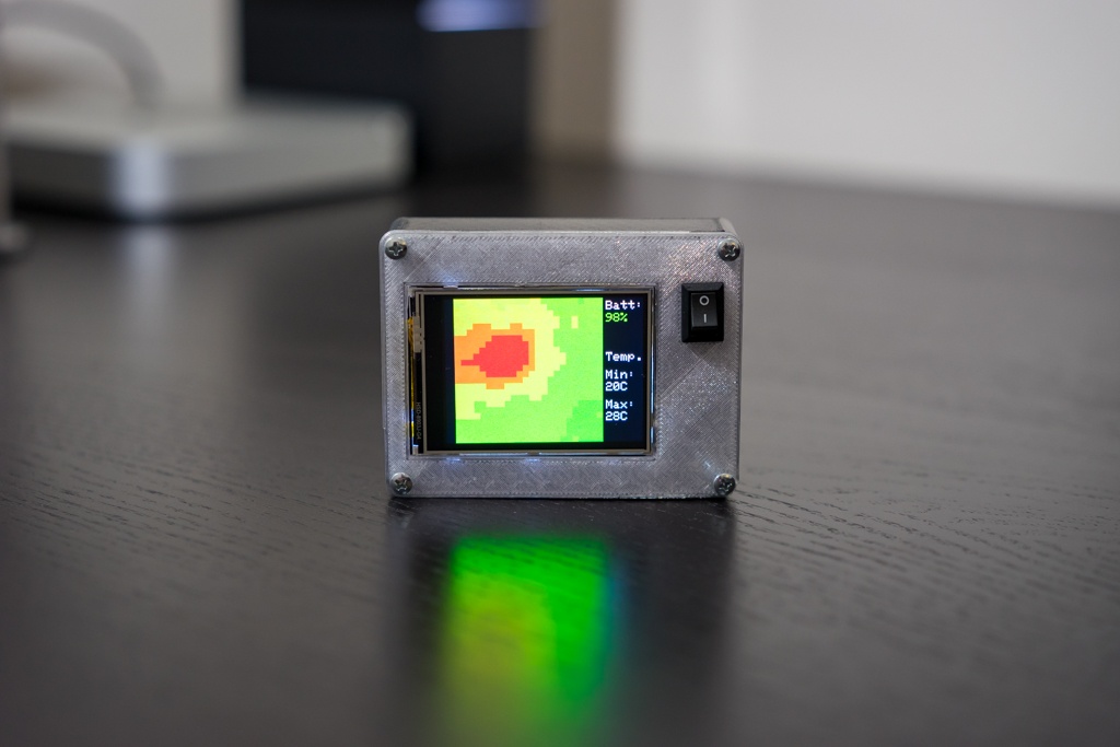
Battery status/charge.
Min./Max. temperature values represented by light blue areas (min.) and dark red areas (max.) on the LCD screen.
Temperature range adjustment by tapping on the screen’s lower right corner. There are 3 temperature ranges to choose from:
28C to 30C
20C to 80C
50C to 100C
When switching between ranges, the min. and max. temperature values are shown on screen.
I’m also including the files of a 3D printed case I designed to hold all components in a relatively small package.
Touch Screen Thermal Camera with Adjustable Temperature Range – [Link]
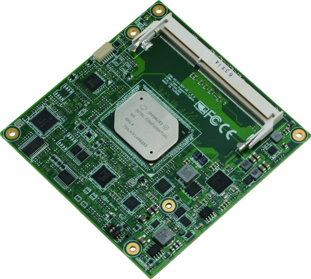
(Taipei, Taiwan – July 3, 2018) – AAEON, a leading manufacturer of embedded controllers, launches the COM-APLC6, a powerful COM Express Type 6 module. Responding to customer requirements and market trends, the innovative tech giant has fitted its latest module with a series of features designed to strengthen applications and speed up development processes.
Powered by an Intel Atom E3900 Series processor, the COM-APLC6 can reliably handle huge amounts of data and is therefore well suited for modern IoT applications. The module features two SODIMM sockets that support DDR3L-ECC memory. Most competing products have non-ECC memory, which is less stable and more prone to data loss, especially in harsh environments. By providing a more dependable solution, AAEON is ensuring that your systems run smoothly even when they’re deployed in the field or harsh, factory environments.
The CPU’s increased graphics capabilities mean this controller can also be used in advanced medical imaging applications. The module has three independent display outputs, including DDI, eDP/LVDS, and VGA interfaces. The COM-APLC6, which has an operating temperature range of 0oC to 60oC, houses a micro SD slot, providing additional, swappable storage. There’s also an interruptible GPIO and support for multiple USB slots and SATA slots, making this a highly expandable module.
We do everything we can to help customers cut the length of time their applications are in development,” said David Hung, AAEON embedded computing division product specialist. “In addition to developing cutting-edge hardware, we’ve also updated our EC firmware so users can quickly and easily implement new features.
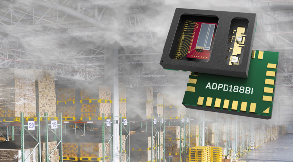
With the introduction of the ADPD188BI, Analog Devices (ADI) kills two birds with one stone: First, this smoke detector meets the latest international regulatory standards. Second, the device that integrates two LEDs, photodiode, and analog front-end (AFE) in a single package, help reduce false alarms often caused by steam and dust.
The ADPD188BI is engineered to meet new UL217 requirements as well as EN54/14604 specifications. Its integrated design uses two colors to separate particle sizes, increasing the ability to detect and classify smoke types and reject nuisance sources. The ADI solution enables a back-scattering design with closer proximity of the LED to the photodiode, reducing circuit board size and allowing for smaller smoke detectors that are more architecturally compatible for residential and commercial use.
Screen technologies have evolved over the years since the cathode ray tube was first demonstrated in 1897, we have moved from plasma to LCDs, followed by LEDs, OLEDs, and more recently e-paper which is what we will look into today. Electronic paper/e-paper displays are display devices which were created to mimic the appearance of ink on a common paper. Unlike the other kind of displays which emit light, e-paper displays reflect light just like an ordinary paper. This gives e-paper displays a wider viewing angle, ensure they consume less power and makes looking at them easier as it gives the same feel as looking at an ordinary paper without the glare that comes from looking at a screen. The coolest feature of this display is its ability to display the last text or graphics uploaded to it even when it is not connected to power. This helps save a lot of power and is the key feature for most applications for which e-paper displays are deployed.
The popularity of e-paper displays is on the rise (used in Amazon’s Kindle) due to the unique features mentioned above, that’s why, for this tutorial, we will look at how to use e-paper displays in Arduino projects, to give the projects an extra layer of sophistication and coolness.
Using Waveshare 4.3″ E-paper Display with Arduino – [Link]
Screen technologies have evolved over the years since the cathode ray tube was first demonstrated in 1897, we have moved from plasma to LCDs, followed by LEDs, OLEDs, and more recently e-paper which is what we will look into today. Electronic paper/e-paper displays are display devices which were created to mimic the appearance of ink on a common paper. Unlike the other kind of displays which emit light, e-paper displays reflect light just like an ordinary paper. This gives e-paper displays a wider viewing angle, ensure they consume less power and makes looking at them easier as it gives the same feel as looking at an ordinary paper without the glare that comes from looking at a screen. The coolest feature of this display is its ability to display the last text or graphics uploaded to it even when it is not connected to power. This helps save a lot of power and is the key feature for most applications for which e-paper displays are deployed.
The popularity of e-paper displays is on the rise (used in Amazon’s Kindle) due to the unique features mentioned above, that’s why, for this tutorial, we will look at how to use e-paper displays in Arduino projects, to give the projects an extra layer of sophistication and coolness.
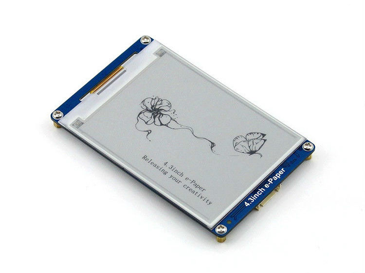
4.3″ E-paper Display
E-paper displays come in different sizes like every other kind of display, but for this tutorial, we will use the Waveshare 4.3″ e-paper display. Some of the features of this display are listed below.
Easy to use, display any content via one serial interface, including geometric graphics, texts, and images
Embedded font libraries, supports 32, 48 and 64 dot matrix GBK Chinese fonts and English fonts
Built-in 128MB NandFlash, allows the font/image data to be stored in either an external TF card or the internal NandFlash
4 grey level displaying, 800×600 resolution
Adjustable serial interface baud rate, 115200 by default when power up
Powered from 3.3V to 5V, compatible with 3.3v/5v logic level.
Ultra low power consumption, sleeping current lower than 5mA
Our basic goal with this project will be to display basic text and graphics on the e-paper display, by doing this, we will be able to cover the functions that may be needed for you to use the e-paper display in your own custom projects.
Required Components
The following components are required to build this project;
As usual, the exact version of the components used for this tutorial can be bought via the links attached to each of them. The link attached to the e-paper display above takes you to the page where you can acquire the 4.3″ e-paper display but any other display size can be used for this tutorial.
Schematics
E-paper display generally uses UART protocol for communication with microcontrollers. The display has five pins including;
VCC
GND
Din (data in pin)
Do (data out pin)
Wake up pin
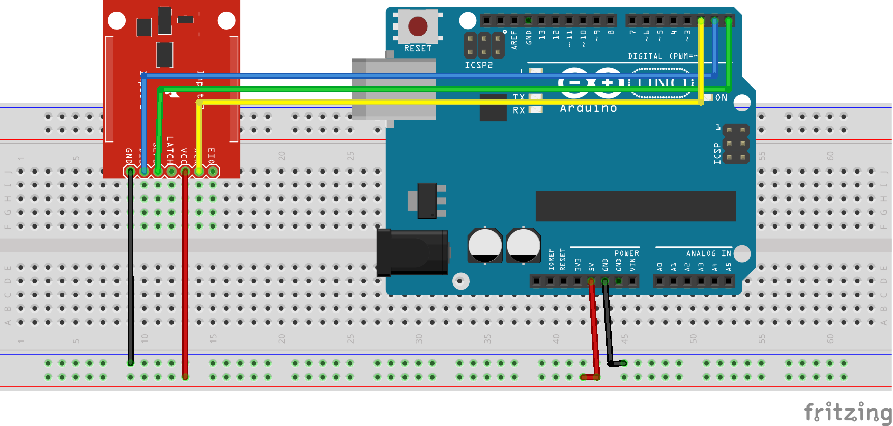
Connect the display to the Arduino as shown in the schematics below. Depending on the accessories that come with your own display, you may need to use a breadboard or not.
Schematics
To make the connections easier to follow, the pin connection between the Arduino and the e-paper display is further described below.
Display – Arduino
VCC - 5v
GND - GND
DIN - RX(D0)
DOUT - TX(D1)
Wake - D2
Code
Just like the schematics, the code for this project is equally easy. For this project, we will use the e-paper display library provided by Waveshare. The library can be downloaded from the download section towards the end of this post. To demonstrate the abilities of the e-paper display, we will use the demo code provided along with the library. The demo code provides commands needed to display images and text on the e-paper display. Due to the low refresh rate of this particular e-paper display, it cannot be used to display animations, but this may be possible with other e-paper displays which have better refresh rates.
To briefly explain the demo code, as usual, we start by including the libraries that will be used in the code, in this case, the epd.h library to enable easy communication with the e-paper display.
#include <epd.h>
Next is the base_draw function which contains the functions to draw a different kind of shapes from lines to the rectangle,
void base_draw(void)
{
  int i, j;

  /*
  draw pixel
  */
  epd_clear();
  for (j = 0; j < 600; j += 50)
  {
    for (i = 0; i < 800; i += 50)
    {
      epd_draw_pixel(i, j);
      epd_draw_pixel(i, j + 1);
      epd_draw_pixel(i + 1, j);
      epd_draw_pixel(i + 1, j + 1);
    }
  }
  epd_udpate();
  delay(3000);

  /*
  draw line
  */
  epd_clear();
  for (i = 0; i < 800; i += 100)
  {
    epd_draw_line(0, 0, i, 599);
    epd_draw_line(799, 0, i, 599);
  }
  epd_udpate();
  delay(3000);

  /*
  fill rect
  */
  epd_clear();
  epd_set_color(BLACK, WHITE);
  epd_fill_rect(10, 10, 100, 100);

  epd_set_color(DARK_GRAY, WHITE);
  epd_fill_rect(110, 10, 200, 100);

  epd_set_color(GRAY, WHITE);
  epd_fill_rect(210, 10, 300, 100);

  epd_udpate();
  delay(3000);

  /*
  draw circle
  */
  epd_set_color(BLACK, WHITE);
  epd_clear();
  for (i = 0; i < 300; i += 40)
  {
    epd_draw_circle(399, 299, i);
  }
  epd_udpate();
  delay(3000);

  /*
  fill circle
  */
  epd_clear();
  for (j = 0; j < 6; j++)
  {
    for (i = 0; i < 8; i++)
    {
      epd_fill_circle(50 + i * 100, 50 + j * 100, 50);
    }
  }
  epd_udpate();
  delay(3000);

  /*
  draw triangle
  */
  epd_clear();
  for (i = 1; i < 5; i++)
  {
    epd_draw_triangle(399, 249 - i * 50, 349 - i * 50, 349 + i * 50, 449 + i * 50, 349 + i * 50);
  }
  epd_udpate();
  delay(3000);
}
The next function is the draw text function. Like the base_draw() function, this function has all that is needed to display different text formats.
The next function is the draw_bitmap function. Just like most of the other displays we have worked with on this website, to display an image on the e-paper display, the image has to be in a bitmap format. The draw_bitmap function contains the commands to be used for displaying images on the e-paper display.
Next, is the setup function. We start the function by declaring the led connected to pin 13 on the Arduino. This led is used as a user initialize LED to confirm communication between the Arduino and the display. With this done, we then initialize the display, activate the wakeup… and set the memory which we want the display to use. The display can either use the onboard NAND memory or an SD card.
void setup(void)
{
  /*
  user led init
  */
  pinMode(led, OUTPUT);
  digitalWrite(led, LOW);

  epd_init();
  epd_wakeup();
  epd_set_memory(MEM_NAND);
}
The tasks being performed by the void loop function are simple. All it does is to call the functions that were created above one after the other.
void loop(void)
{
  char flag = 0;

  base_draw();

  /*
  Draw text demo
  */
  draw_text_demo();

  /*
  Draw bitmap
  */
  draw_bitmap_demo();

  epd_enter_stopmode();
  while (1)
  {
    if(flag)
    {
      flag = 0;
      digitalWrite(led, LOW);
    }
    else
    {
      flag = 1;
      digitalWrite(led, HIGH);
    }
    delay(500);
  }
}
The complete code can be downloaded alongside the library from the download section of this tutorial.
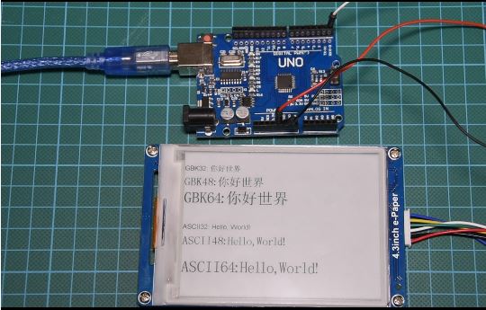
Demo
Before uploading the code for this project, disconnect the Din and Dout pins of the display from pins D0 and D1 of the Arduino. This is to allow a smooth upload of the code as those particular pins will also be used by the Arduino to communicate with the computer. Connect the pins back after uploading the code to the Arduino, and wait a few secomds. You should see the display come up with different images and text.
That’s it for this tutorial guys, what cool thing will you build with this display, feel free to share ideas under the comment section below.
The youtube version of this tutorial can be watched here.
Most of the temperature measurement techniques around the world require some sort of physical contact between the temperature sensor and the object or environment whose temperature is to be measured, but as technology advanced, this changed too. The need to be able to measure the temperature of an object without physical contact arose. This need brought the measurement of temperature using infrared sensors.
The principle of operation of Infrared thermometers is simple, all bodies at a temperature above 0°Kelvin (absolute zero) emit an infrared energy which can be detected by the infrared thermometer sensor. It’s design includes a lens that focuses the infrared energy being emitted by the object in front of a detector. The detector converts the energy into an electrical signal which then can be passed to a microcontroller to interpret and display in units of temperature after compensating for the variation in ambient temperature.
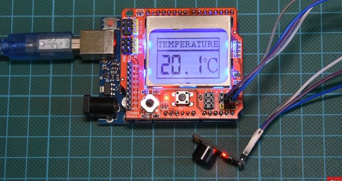
Today, we will build a DIY Infrared based thermometer using an Arduino Uno, the MLX90614 IR temperature sensor, and a Nokia 5110 LCD display shield to display the measured temperature.
Infrared Thermometer with Arduino and MLX90614 Temperature Sensor – [Link]
Most of the temperature measurement techniques around the world require some sort of physical contact between the temperature sensor and the object or environment whose temperature is to be measured, but as technology advanced, this changed too. The need to be able to measure the temperature of an object without physical contact arose. This need brought the measurement of temperature using infrared sensors.
The principle of operation of Infrared thermometers is simple, all bodies at a temperature above 0 Kelvin (absolute zero) emit an infrared energy which can be detected by the infrared thermometer sensor. It’s design includes a lens that focuses the infrared energy being emitted by the object in front of a detector. The detector converts the energy into an electrical signal which then can be passed to a microcontroller to interpret and display in units of temperature after compensating for the variation in ambient temperature.
Today, we will build a DIY Infrared based thermometer using an Arduino Uno, the MLX90614 IR temperature sensor, and a Nokia 5110 LCD display shield to display the measured temperature.
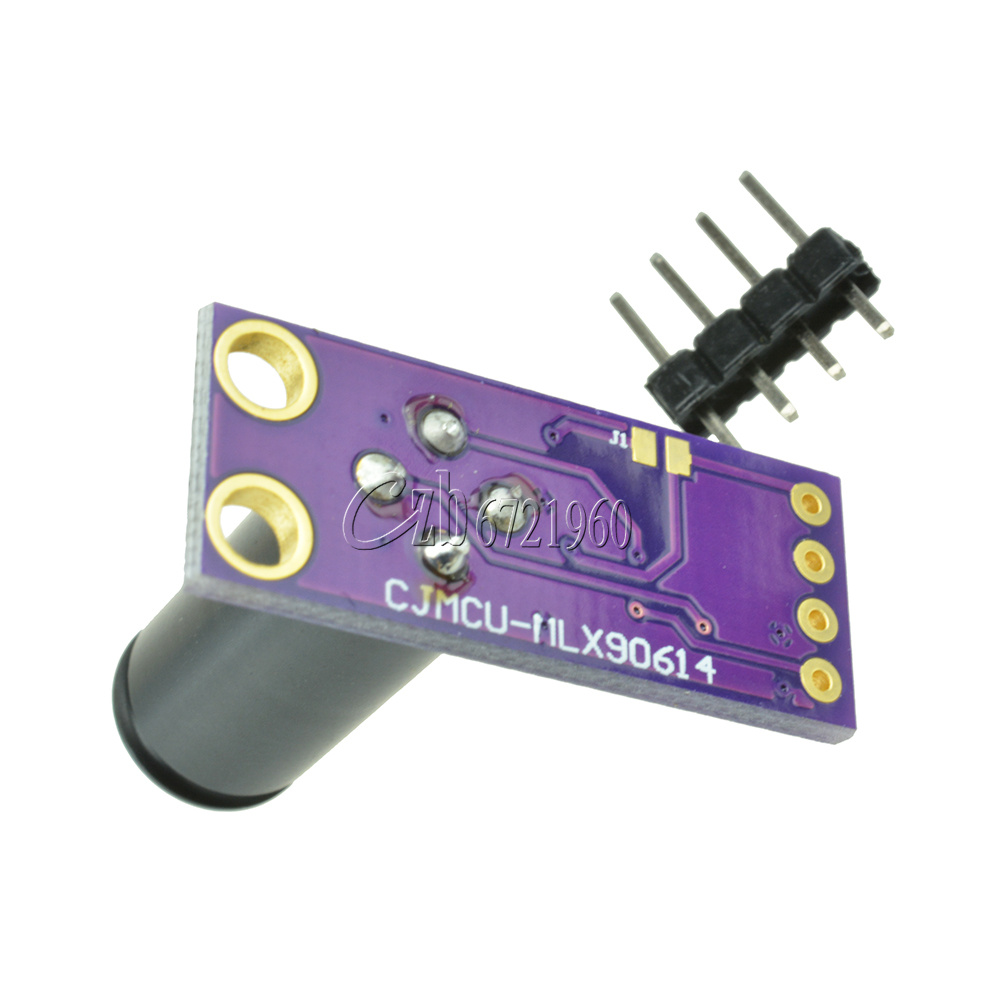
The MLX90614 is an infrared temperature sensor for non-contact temperature measurement. It can measure temperatures within the range of -70 to 380 degree Celsius with an accuracy of about 0.5C at room temperature.
Some of the features of this sensor are listed below:
Small size and low cost
Easy to integrate
Factory calibrated in wide temperature range: -40 to 125°C for sensor temperature and -70 to 380°C for object temperature
High accuracy of 0.5°C over a wide temperature range (0..+50 C for both Ta and To)
Measurement resolution of 0.02°C
Single and dual-zone versions
SMBus compatible digital interface for fast temperature readings and building sensor networks
Customizable PWM output for continuous reading
Available in 3V and 5V versions
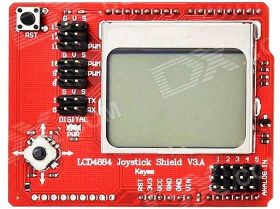
For this tutorial also, for the first time, we will use the Nokia 5110 LCD shield, while we have used the other version of the display several times we have never used the shield version. The shield comes with a joystick and a button. It is pin compatible with the Arduino Uno and most other Arduino boards.
Required Components
The following components are required to build this project:
As usual, the exact components used in this tutorial can be bought via the links attached to each of the components above.
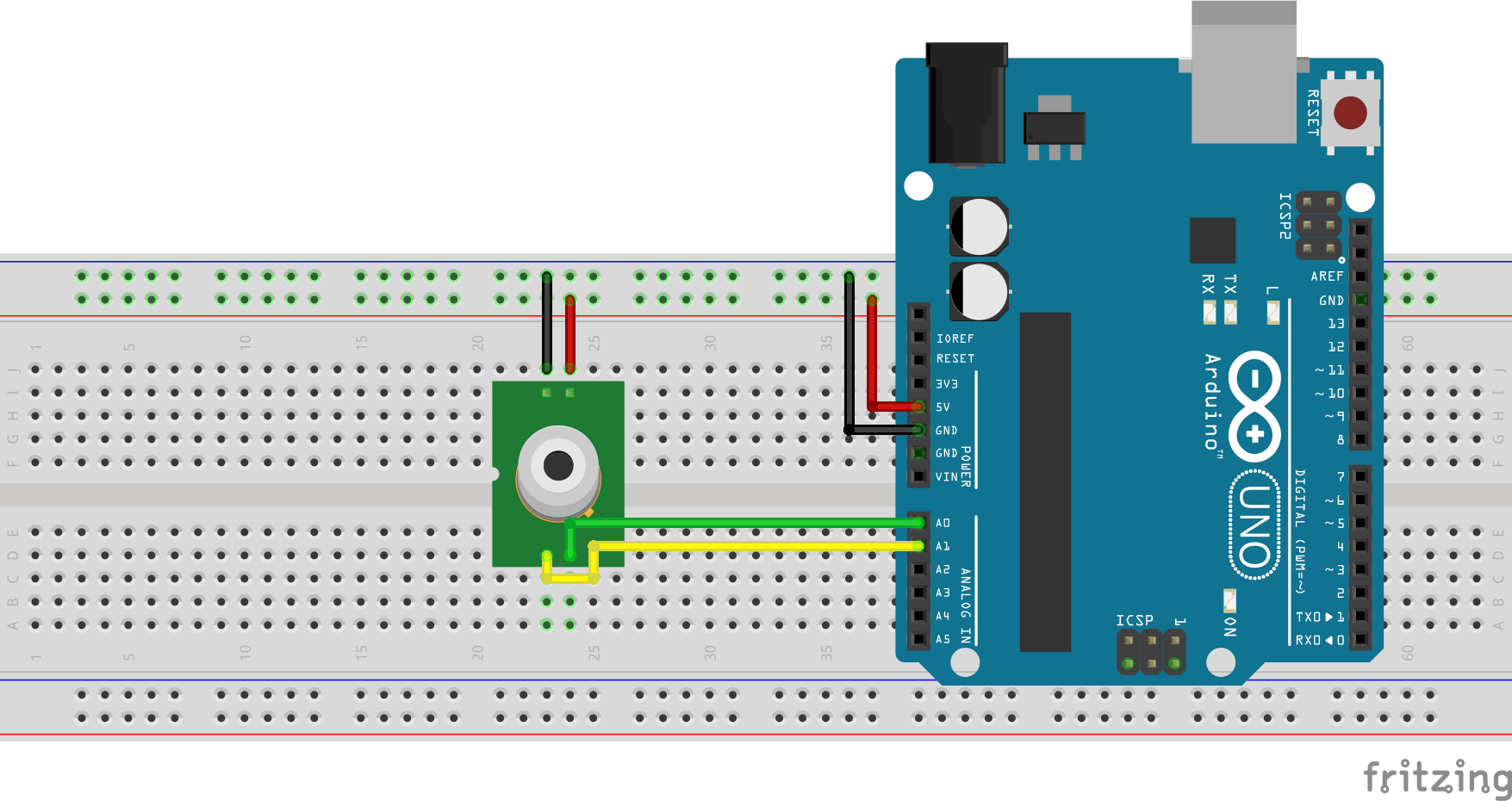
Schematics
The schematics for this project is very easy because the display comes as a shield which takes away the need to connect it via wire and all we need to do is to plug the display on the Arduino. The connection between the Arduino and the temperature sensor is shown in the schematics below.
Schematics
To make the connections easier to follow, the connection is further detailed below.
MLX90614 – Arduino Uno
VCC  - 5V
GND  -  GND
SCL  - A5
SDA  - A4
Go over the connection once again to ensure everything is as it should be.
Code
Our goal for this project is to measure the temperature, process it and display it on the LCD. To enable us to communicate easily with the mlx90614 temperature sensor, we will use the mlx90614 temperature sensor library from Adafruit and the Nokia 5110 LCD graph library for easy display of text on the screen. The libraries can be downloaded via the link attached to each of the libraries in the sentence above.
To briefly explain the code for the project, we start as usual by including all the libraries that will be needed in the code.
# Written by Nick Koumaris
# info@educ8s.tv

#include <LCD5110_Graph.h>
#include <Wire.h>
#include <Adafruit_MLX90614.h>=
Next, we create an object of the LCD library, specifying the pins of the Arduino to which the LCD pins are connected.
LCD5110 lcd(2,3,4,6,5); //Use this line with the shield
With this done, we create variables for the fonts and other elements that are needed for the display after which we create an instance of the temperature sensor.
Next, we write the void setup function. We start the code by initializing the LCD and temperature sensor after which we use the LCD.drawbitmap() to create the user interface on the display. The interface had already been designed and converted into a C-file and is already attached to the code. The reason for using the UI is to be able to display the data in a more user-friendly and efficient way. We have done a lot of tutorials in the past that show how to create custom graphics for the Nokia 5110 LCD display. One of such tutorials can be accessed here.
Next, is the void loop function. The scope of the void loop function is simple. We start by determining the unit of measurement in which the temperature is to be displayed either in Celsius or in Fahrenheit, then we read the temperature from the temperature sensor and display it on the display. For accuracy, a time delay of 1000ms as inserted in between readings to ensure and prevent read requests from clashing.
The complete code for the project is attached to the download section at the bottom of the page.
Demo
Ensure the project is wired up as described in the schematics section. Copy the code and upload to the Arduino board, then point the temperature sensor to an object whose temperature you wish to measure. After a while, the temperature of that object will be shown on the screen.
Asides non-contact temperature, the MLX90614 IR temperature sensor can also be used to measure the ambient temperature but we won’t be considering that for this tutorial.
Some of the major applications of this project include:
Heating and air conditioning
Systems monitoring – Monitoring the performance of cooling systems, boiler operations, steam systems and detection of hot spots in electrical/electronics systems and panels
Agriculture – Monitoring the temperature at which food is being processed and stored
That’s it for this tutorial guys, do let me know via the comment section if you have any questions. The video version of the tutorial can be watched on youtube here.
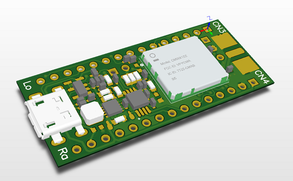
Lora board with Arduino nano compatibile pinout and simple battery management. Small board with arduino nano compatibile pinout with power management and Murata ABZ LoRa module with STM32L0 microcontroller
Features:
LoRa module: Murata ABZ
Single cell LiPo cell charger on-board with charging signal internally connected to PA11 (via jumper)
Buck/Boost switching power supply for delivering stable 3,3V regardless of the battery voltage
Battery fuel gauge on-board to control the real status of the battery
PCBWay, is a leader in the manufacture of PCB and PCBA services and a friend of the community who always have interest of the maker’s community. We have seen PCBWay has put a lot of effort providing sponsorship for PCB based projects already, but they are not stopping there. PCBWay is continuing this community grooming with the PCBWAY PCB SHARE PLAN, an initiative to allow makers and engineers to give back to the community and get paid for their efforts.
The PCBWay PCB Share Plan is a project sharing plan set up by PCBWay to ensure the growth of the community in general. This was done to make sure community members help each other reach their peak. Sharing of information is regarded as good practice by PCBWay and is therefore greatly encouraged.
Anyone who has a PCB (printed circuit board) project can share it with community. PCBWay is not trying to dig out the experts in the field as the goal is to help those experts get about their self-acclaimed peak. This means that both amateurs and professionals can share projects. This will be super easy because editors are always available to offer assistance with editing and publication.
Another interesting and amazing perk that comes with sharing your projects is that after releasing an Open Source PCB (printed circuit board) design, you can put it up for sale and when people buy, you get a 10% commission of the total PCB (printed circuit board) cost.
WHAT IS ACCEPTED?
Basically, everything based on Printed Circuit Boards (PCBs) through different methods of teaching such as:
Tutorial: This method of teaching is such that even an amateur can create the same device just by following your instructions.
Showcase: Mostly done by professionals, this method simply shows the end and does not include the means. This means that only the result is shown and there are neither a detailed explanation nor a set of instructions.
Work in progress: Some people feel documentation is critical and so they release documentaries of their work as they progress. This is very helpful because the public can learn how to build or design step by step.
Protip: Showing and describing solutions of a single challenge. One can choose a specific problem related to printed circuit boards and solve it by describing what to do if a person is faced with that challenge.
Teardowns or Unboxings: Deep explanation about a specific software or hardware. This often involves continuous teaching for weeks to ensure there is enough knowledge passed on to others about the topic
Getting started guides: This method of teaching describes what to do when you are new to a software or hardware. It merely explains what to do when you’re an amateur.
HOW TO SUBMIT
Submission is very easy and can be accomplished by following these set of instructions:
Step 2. Click ‘PCB Instant Quote’ link on the header fill in PCB Specification Selection > Calculate > Add to Cart > Upload your PCB files.
Step 3. Click ‘Share & Sell’ button on the shopping cart/order list > Choose an excellent cover image for your project
PCBWay Project Sharing Process
PCBWay is hoping to build a better maker’s community and fostering the next-gen technology by recognizing the talent and effort makers around the world while offering them some incentives. For more information about PCBWay Project Sharing, visit the project sharing page.
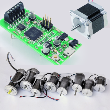
It is open source and based upon the ATmega32U4 microcontroller, and provided with drivers for two DC brush motors and a stepper motor. It receives commands via USB or serial ports, or via the I²C bus.
For those dealing with robotics, one of the problems to solve is the management of the motors used for the traction, that is to say: how to correctly power the motors needed in order to make your robot advance. If you work with Arduino, the first and immediate solution is to use a shield. Several of them can be found available for sale, from the simplest ones that allow to control separately the two small DC motors, to the most advanced ones that are able to measure the current drawn as well. Regardless of the manufacturer, the shields are all based on the usage of a power driver (usually the L298), that is directly interfaced to Arduino’s PWM outputs, and encircled by a few other components. Surely the usage of a shield is a valid solution, but then we need to use at least four Arduino outputs: usually two to adjust the speed and two for the direction. If, on the other hand, you use a generic microcontroller, or a stand-alone Atmel chip, or a board that is different from Arduino, things get a bit more complicated, since on the market it is difficult to find drivers with a more flexible interface, and the price starts to rise quickly. If you then have the need to command two motors, things get very complicated, even for those using an Arduino board, because problems arise both on the hardware and on the device programming point of view.