PCB Sponsorship for Non-Profit Projects and Crowd Funding Projects

PCBWay is a leader in the manufacture of PCB and a reliable PCBA services. PCBWay doesn’t only work with makers but they are giving back to the maker’s community. PCBWay has sponsored over 800 PCB based projects coming from students, teachers, electronics engineers and other people who showed interest in electronics. However, what is being offered now by PCBWay is a win-win coin, as both sides are profitable for the parties concerned.

The first half of the coin deals with students and teachers. Due to a change in the policy, any student or teacher can apply and be sure of sponsorship. The only qualification for application is that the project must have a PCB included. PCB is simply an acronym for Printed Circuit Board, and these are boards that make use of lines and pads to connect various points electronically. One can design a Printed Circuit Board using a CAD package like KiCAD, DripTrace, Eagle CAD and others. If you want to learn about making your first PCB with PCBWay, read our getting started series.

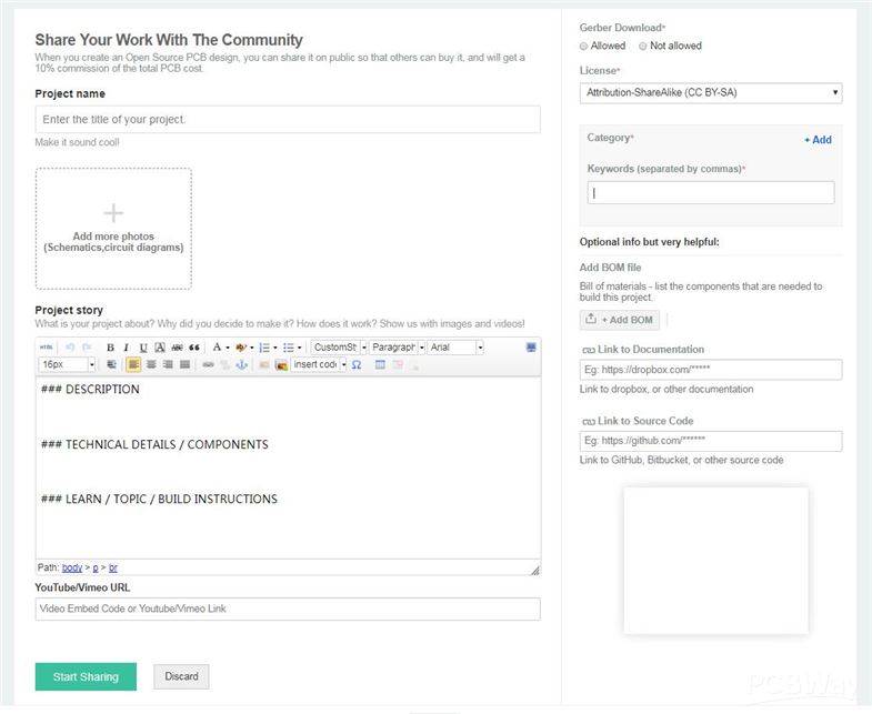
The progress of applying for support is no longer complicated. The application for sponsorship is pretty and can be completed after four super easy steps.

  1. Describe your team and project with appealing words and pictures as detailed as possible.
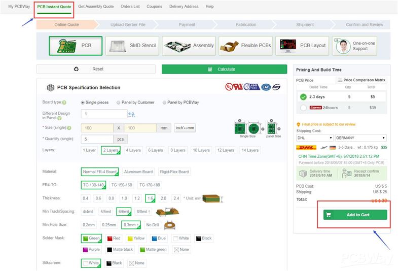
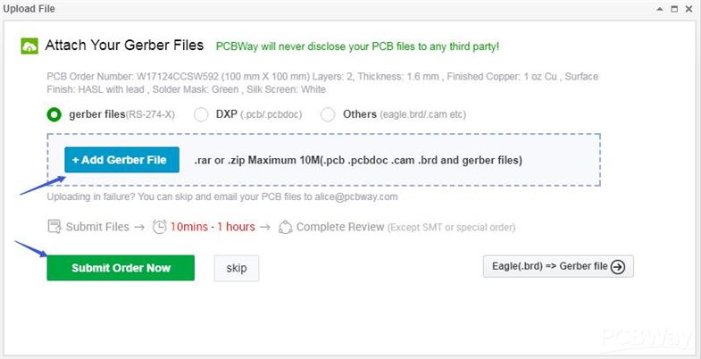
  2. Upload your PCB files to PCBWay online quote system for placing your order.
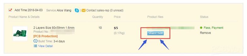
  3. Get a coupon after your articles pass the audit stage.
  4. Share PCBWay’s sponsor page to get more coupons.

This sponsorship has five different stages according to PCBWay:

  1. Engineering Projects Sponsorship: PCBWay.com is confident about the quality of their PCBs, and now they offer sponsorship for the projects from students and engineers. For university/college students and teachers, all you need to do is use your high school address as shipping address. Upload some few details about your project such as your university/college Name, the nature of your projects, and other necessary supporting materials to PCBWay for the sponsorship code. For engineers, all you need is to describe your projects as detailed as possible so that it can convince them that your projects are great enough and worth a sponsorship. They will check the details of your request and send you the coupon in 24 hours. You can use that coupon at checkout. Get started today.
  1. Sponsorship of Competition PCBs: Please always check for your future orders of competition PCBs, they can be entitled to a bigger discount or even free. This will be determined by the nature of the competition and its impact. You may be asked to provide a little more details about the competition to help PCBWay assess your case. This is considered on a case by case basis. Try to Post your project as you may save a lot. It’s possible that all your competition PCBs will be free.
  1. Shipping for sponsorship PCBs: Sponsorship is for PCB related service offered by PCBWay, but not include the delivery. So you need to pay for the shipping charge of the sponsorship PCBs.
  1. PCB Assembly Service: Though not free, PCBWay.com will offer a significant discount on the PCB Assembly Services for students and teachers. Please contact the customer service.
  1. Discount for Future Orders

PCBWay.com offers a 10-15% discount on future orders from teachers and students. This covers the PCBs for classroom projects, team or club projects and all kinds of students’ competitions.

Flipping over the coin, the other half is open to everyone, this means students, teachers, engineers, experts, and even amateurs can participate. $50,000 has been budgeted for the crowdfunding project support in 2018 and every month five $100 cash coupons will be given out via Twitter. The project has to be based on PCBs. All projects and ideas should be sent to sponsor@pcbway.com for evaluation.

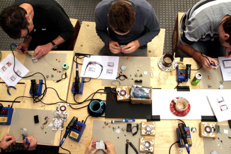
PCBWay is hoping to build a better maker’s community and fostering the next-gen technology by recognizing the talent and effort of the best electronic designers around the world. For more information about PCBWay Project sponsorship, visit the sponsorship page.

An introduction to GPIO Settings

Working with microcontrollers means managing GPIO pins at some point. Many configurations have been developed for modern microcontrollers which can lead to some “fancy” terms that may confuse programmers. Its important to understand all of this to avoid confusion and errors while programming.

First, some terms need to be understood. GPIO pins have tri-state logic which means that contrary to popular beliefs GPIO pins can assume 3 states instead of 2. These values are: 0, 1 and high impedance or “Hi-Z”. There is also a state called floating which is when the state is indeterminate and floats between two states. As a result, the pull up and pull down were created, the pull up are resistors that connect a signal to VCC when the signal is floating, and pull downs do the same, but connect the signal to ground. Also, there is a “current sink” which is when the current is flowing into a pin, node, or signal. Conversely, there is a “current source” which is when the current is flowing out of a pin, node, or signal.

The modes of a GPIO pin can be classified into two categories: input, and output. Input mode means that the pin is used to read the state of the electrical signal, they are configured as high-impedance, pull up or pull down. Output modes are used to write a signal as high or low using push-pull or open drain. Push- pull is the default setting in most cases and it works by sourcing or sinking the current. On the other hand, Open- Drain only sinks current which basically makes it a switch with 2 states ground or disconnected. A useful application is for having multiple external devices drive a single, active low interrupt pin.

Regarding functionality, speed is a very important and desired characteristic for GPIO pins since it controls the rate at which it changes state. Speed configurations are referred as “slew rates”, “frequency”, and “high frequency mode”. Increasing speed leads to higher power consumption and a noisier device, so people tend to keep it low unless the project specifically requires more speed.

Another term is “High Drive” GPIO which are push-pull pins that provide more current that usual. These characteristics depend on the device and its recommended to check the datasheet, for example: if a typical GPIO can source/sink 8 mA a high drive device can source/sink 40 mA.

By reading this its easy to notice that the definitions are mostly things we are familiar with, and the only novelty are the terms used to describe them.  Learning and understanding all the modes, functionalities etc. will make working with GPIOs easier and could avoid any issues. You can learn more about GPIO states on the source below.

[source]

my-ssd1306 an HTML interface to SSD1306 OLED display

My-SSD1306 allows you to connect any device equipped with RS232 to the I2C SSD1306 displays.

My-ssd1306 board should be put between the RS232 source and the I2C SSD1306 target. Two series of connection pins are provided both have VCC, GND, SDA and SCL but one serie has the VCC and GND swapped to allows a direct connection via a connector because some commercial displays have these two pins inverted.

my-ssd1306 an HTML interface to SSD1306 OLED display – [Link]

LoRa-to-Ethernet Gateway

A WIZ750SR based device that allows sending and receiving messages over LoRa and LoRaWAN.

I got some LoRa modules with SPI communication interface. One of the options it would have been to connect them to my Raspberry Pi. But, I didn’t really like the idea because I already have some stuff connected to my Raspberry Pi, and this starts getting unmanageable.

So, I decided to create a LoRa-to-Ethernet gateway that I can connect directly to home router. The WIZ750SR module with its Ethernet interface and Cortex-M0 SoC it’s a great candidate for this.

LoRa-to-Ethernet Gateway – [Link]

High Efficiency MPPT Solar Charger

A 75 watt MPPT Solar Charger with tons of features. Efficiency > 97%, USB interface, data logging, 2 USB charging ports and much more…by Lukas Fässler

This is an open source project that I’ve been working on for several years now. From its modest beginnings it has evolved to a rather sophisticated device with a USB interface, powerful USB charging ports, a 20×4 character LCD, a rotary encoder with push button, precision measurement of everything from temperatures, voltages and currents. There are 4 switchable power outputs, a year’s worth of data logging with real time clock and calendar. It connects to a desktop app via USB where users can monitor and adjust every aspect as well as see what the charger did while they were away.

High Efficiency MPPT Solar Charger – [Link]

AAEON’s Intel Core-Powered PICO-KBU4 will Help Your Applications Take Flight

(Taipei, Taiwan – June 19, 2018) – AAEON, a leading developer of embedded controllers, announces the launch of the PICO-KBU4, a rugged and expandable compact SBC with the capacity to revolutionize the field of robotics and open up the drone market for x86 embedded controllers.

Fitted with a 7th Generation Intel® Core™ i processor (formerly Kaby Lake) and featuring up to 16GB DDR4 SODIMM memory, the PICO-KBU4 has the computing power to handle applications previously only possible with much larger motherboards. Its market-leading pair of GbE LAN ports enable the use of two HD cameras, and with its GPIO, two COM ports, two USB3.0 ports, and two USB2.0 pin headers, it can connect to and control a range of sensors.

The PICO-KBU4’s compact, lightweight specifications are an obvious advantage with drones, robotics, and even conventional, factory machine vision systems. The board can be used in spaces once considered too small to house a powerful embedded controller, and its low power-consumption figures are an additional benefit with battery-reliant drones.

A 0oC~60oC operating temperature range, HDMI and LVDS ports, SATA slot, and M.2 B and E keys for extra storage and WiFi / Bluetooth connectivity make this an extremely flexible SBC, and customers can expand the already impressive IO interface by adding a custom-made daughter board via an optional board-to-board interface.

“This board’s combination of high-performance computing with a small form factor mean it will be the future of not only factory automation systems, but also robotics, and advanced drones,” said Jones Huang, AAEON embedded computing division product manager. “Any drone equipped with a PICO-KBU4 will be able to stay in the air for a long time, and that will make it a powerful surveillance tool or air quality monitor.”

The Internet of Arduino Challenge – Build an IoT Arduino Powered Product and you could win up to $50,000

The Arduino has been the number one development board for hackers, hobbyists, engineers and even product designers for a while. The Arduino Movement has powered a powerful maker’s community where anyone that can think of an idea can quickly make it happen, and this has birthed several Arduino powered products.

The Internet of Things is steadily becoming the talk of the day with several millions of devices getting connected every hour. The Internet of Things is expected to disrupt our everyday lives by giving us more insight into our daily data thereby improving our lives. Imagine giving cars the ability to detect portholes on the road when driving; this data can be collected, aggregated and possibly predict the likelihood of a road accident (due to bad roads), traffic congestion, and also the overall state of the road. If this information is given to the right body, they can know what roads they should focus their resources on.

To give people the chance to build an IoT focus product, the Arduino movement has released several IoT focused boards like the Arduino MKR 1000, Arduino Yun, Arduino Vidor 4000, Arduino Industrial 101, Arduino Plus Esp8266, and several others. You can find more Arduino IoT boards here. Now, the Arduino Movement in partnership with the electronics supplier Arrow and Indiegogo wants to give more power to the maker’s community by creating an Internet of Arduino Challenge where winners can go and win up to $50,000 in funding.

The contest is all about creating an IoT product that is powered by an Arduino board. The possibilities are endless with Arduino. Pair that with the engineering and production resources from the Arrow Certification Program, and you can have the next successful Indiegogo campaign. Submit your design now for a chance to win $50,000 in funding. Entries opened May 12th, 2018, and ends August 31st, 2018.

The IoT revolution is beginning, and it will change the way we think and work. In fact, many of the mindless activities we perform on a daily or weekly basis can go away entirely, leaving us more time to read, play with the kids or go on that nice long weekend ride. It will also advance every company in the world. Companies must begin a digital transformation, or they might go out of business. Even if you don’t win the challenge, you will never lose because, in this developing IoT Industry, there is never a loser.

We are on the cusp of a new revolution. It will be very similar to when the internet began to take shape in the early 2000s. Many companies weren’t quite prepared. Some fought the revolution. Some ignored it. Those companies are no longer.

Linux Powered Apalis iMX8 SoM Built On NXP’s QuadMax

Toradex, a Swiss embedded technology firm announced the world’s first embedded board built on NXP’s i.MX8 QuadMax back in Mar. 2017. Recently, Toradex has opened early access for selected customers to the SODIMM-style Apalis iMX8 module. A sign-up form offers the potential for newcomers to get an early look.

Apalis iMX8 module
Apalis iMX8 module

This new Linux powered, wireless-enabled Apalis iMX8 uses the QuadMax, which is the most powerful i.MX8 Quad model. Like the Quad and QuadPlus, it offers 4x 1.26GHz Cortex-A53 cores, 2x 266MHz Cortex-M4F cores for real-time processing, one or two Vivante GC7000LiteXS/VX GPUs, and a HIFI4 DSP. The QuadPlus adds a 1.6GHz Cortex-A72 core, and the Apalis i.MX8’s QuadMax provides two -A72 cores. The module supports up to 4 GB LPDDR4 RAM.

The Cortex-A cores run a Yocto Project based Linux distribution provided via a BSP (Board Support Package). The M4F MCU cores run FreeRTOS which is also provided by the same BSP. With its dual GPUs, the Apalis iMX8 supports multiple-screen automotive installations. However, the module is designed for a broader range of cutting-edge computer vision systems, as well as signal processing and HMI applications. The module offers onboard, dual-band 802.11ac WiFi, and the dual-mode Bluetooth module is said to be Bluetooth 5.0 ready.

The module is equipped with 2x PCIe Gen 3 interfaces, 3x CAN, 4x SPI, 7x UART, and 8x analog inputs. The I2C count has increased to 7x, and the PWM count has advanced to 6x. You also get an IrDA connection, up to 133 GPIOs, and 8- and 4-bit SDIO/SD/MMC interfaces. The Apalis iMX8’s SATA interface has moved from SATA II to III. As before, there’s a GbE (Gigabit Ethernet) controller with a second RGMII. You get a USB 3.0 host interface, and 3x USB 2.0 host ports, one of which is OTG.

The module provides a quad-lane MIPI-DSI interface and offers an HDMI 2.0a interface for up to 4K UHD 2160p. There’s also a single/dual-channel LVDS interface with up to 1920 x 1200 x 24bpp resolution and 4-wire resistive touch. One new feature is a choice of DisplayPort 1.3 or eDP 1.4.  An optional 5MP camera module is supported by dual quad-lane MIPI-CSI interfaces. Analog audio I/O includes a stereo line in, mono mic in, and stereo headphone out interfaces.

Apalis iMX8 carrier boards: Apalis Evaluation Board

The Apalis i.MX8 offers the same two carrier board options provided for the Apalis TK1: a 250 x 250mm Apalis Evaluation Board, as well as a less feature-rich, 125 x 90mm Ixora Carrier Board. The boards have real-time clocks and 7-27V DC input support. The Apalis i.MX8 appears to be ready to ship soon to qualified early access providers. You can sign up to apply for early access on the Apalis i.MX8 product page.

Nvidia’s Jetson Xavier is an AI Computer boasting a $10,000 Worth Of Power For Your Machines and Robots

NVIDIA Jetson Xavier is the latest addition to the Jetson platform. It’s an AI computer for autonomous machines, delivering the performance of a GPU workstation in an embedded module for a consumption under 30W. With multiple operating modes at 10W, 15W, and 30W, Jetson Xavier has greater than 10x the energy efficiency and more than 20x the performance of its predecessor, the Jetson TX2.

Nvidia Jetson Xavier Computer On Module
Nvidia Jetson Xavier CoM

Jetson is a product of Nvidia (Nvidia Jetson) and one of the most powerful embedded platforms for computer vision applications and AI on edge. The Jetson platform is a range of computation processor boards which consists of the Jetson TK1, TX1, and TX2. They’re powered by a Nvidia Tegra which utilizes the ARM Central Processing Unit (CPU). Various operating systems can run on them, such as Linux distros and QNX which is a commercial Real-Time Operating System (RTOS) designed primarily for embedded systems. Nvidia is adding now a new more powerful member to the Jetson Platform.

Nvidia is very excited to announce the release of Jetson Xavier, an Artificial Intelligence computer that works with autonomous machines giving off a GPU workstation in an embedded module and now available in a Jetson Xavier Developer Kit $1299 (USD). It has a super high performance of close to 30 trillion operations per second (TOPS).

The Nvidia Jetson Xavier Developer Kit
Jetson Xavier Developer Kit

Jetson Xavier is designed for robots, drones and other autonomous machines that need maximum compute at the edge to run modern AI workloads and solve problems in manufacturing, logistics, retail, service, agriculture and more. Jetson Xavier is also suitable for smart city applications and portable medical devices. Launched at Computex 2018 in Taiwan by Nvidia CEO Jensen Huang, the Nvidia Isaac Platform includes new hardware, software, and a virtual-world robot simulator that makes it easy for developers to create new kinds of robots.

Jensen Huang said at Nvidia’s Monday press conference at Computex in Taiwan,

This is the single longest processor project we have ever done in our company, Xavier has roughly the same processing power as a $10,000 workstation equipped with a graphics processing units. Plus, it’s easy on the power consumption, he added.

Jetson Xavier is capable of more than 30 TOPS (trillion operations per second) for deep learning and computer vision tasks. The 512-core Volta GPU with support for Tensor Cores and mixed-precision compute is capable of up to 10 TFLOPS FP16 and 20 TOPS INT8. Jetson Xavier’s dual NVDLA engines are capable of up to 5 TOPS each. It also has high-performance eight-core ARM64 CPU, a dedicated image processor, a video processor and a vision processor for accelerating computer vision tasks.

It also announced an “Isaac” software development platform for robots and other autonomous machines that run on its Linux-friendly octa-core “Jetson Xavier” module. The NVIDIA Isaac Software Development Kit (SDK) gives you a comprehensive set of frameworks, tools, APIs, and libraries to accelerate development of robotics algorithms and software.

The Isaac robotics software consists of:

  • Isaac SDK — a collection of APIs and tools to develop robotics algorithm software and runtime framework with fully accelerated libraries
  • Isaac IMX — Isaac Intelligent Machine Acceleration applications, a collection of NVIDIA-developed robotics algorithm software
  • Isaac Sim — a highly realistic virtual simulation environment for developers to train autonomous machines and perform hardware-in-the-loop testing with Jetson Xavier

The Jetson Xavier Developer Kit will be available for early access in August and open to the public in October. Developers using a Jetson TX2 or TX1 to develop autonomous machines using the JetPack SDK can sign up to be notified when they can apply for early access by completing a survey. More information may be found in the Xavier product page.

PCBWay 2nd Edition of PCB Design Competition – The Pride Of A Maker

Late of last year, PCBWay, a leading manufacturer in PCB and PCBA, announced the first of it’s kind PCB design contest in close partnership with SpainLabs (Well-known Spanish electronic forum) with amazing prices and even cash prices was offered to some of the best PCB and Product design from several competitors which all ended up in a huge success. In less than 3 months since the end of the first design contest, PCBWay is launching another one design contest for the 2nd edition of the competition.

Everyone has been waiting on their toes for the commencement of the 2nd Edition of PCBWay design contest. As of June 11, information was shared on the competition’s official website that the contest would start soon. This means it is time to get ready with some awesome PCB designs and win fabulous prizes.

This is the second edition of the competition, and the primary goal is to discover hidden gems in the electronics engineering field. The competition is being organized by PCBWay, SpainLabs, YoREPARO, and lastly ATMakers. They are collaborating to create an avenue for talented electronic engineers to generate revenue.

The 2nd edition of this competition has added a new award category to the former only two award category and also comes with subsequent more substantial cash prices as compared to the previous edition. The competition has three award categories which are:

  • The BEST Design Award,
  • The Most Popular Design Award,
  • The ATMaker Award.

THE BEST DESIGN AWARD

This is the award for the best design in the competition.

  • 1st Prize: $1000 in cash + $100 in coupons+ 10000 PCBWay Beans+ Certificate of Awards & Honors
  • 2nd Prize: $500 in cash + $50 in coupons+ 5000 PCBWay Beans+ Certificate of Awards & Honors
  • 3rd Prize: $200 in cash + $20 in coupons+ 2000 PCBWay Beans+ Certificate of Awards & Honors

THE MOST POPULAR DESIGN AWARD

This is the award for the most popular design and not necessarily the best design in the competition.

  • 1st Prize: $1000 in cash + $100 in coupons+ 10000 PCBWay Beans+ Certificate of Awards & Honors
  • 2nd Prize: $500 in cash + $50 in coupons+ 5000 PCBWay Beans+ Certificate of Awards & Honors
  • 3rd Prize: $200 in cash + $20 in coupons+ 2000 PCBWay Beans+ Certificate of Awards & Honors.

ATMaker Award

This is a special prize for a person that excels in assistive technology. The price awards a lavishing $1000 in cash + $100 in coupons+ 10000 PCBWay Beans+ Certificate of Awards & Honors.

Unlike the last contest which was the maiden edition, professionals such as Mitch Athman, Bill Binko, Carlos Navas and the likes have been contacted and will be judges for the competition. These are experts plus several others that have been gotten so that there will be a fair selection process.

  • For “The Best Designs” Awards, winners will be decided by four electronics engineers from SpainLabs, ATMakers, Cornfield Electronics, and PCBWay.
  • For “The Most Popular Designs” Awards, winners will be chosen according to the number of Vote score, Likes, Shares, Gerber Download Orders. There’s a formula that includes every factor on a weighted calculation of the result.
  • For “AT Maker Prize” Award, one winner will be chosen by Bill Binko, founder of ATMakers. His judging would not only be on PCB design but how useful the design would be to the AT community.

There is no limit to the PCB design’s size, layers, theme, or even the quantity of entries as compared to some limits imposed in the first edition. This means you can enter as many times as you want to and there are no restrictions about what you will be entering the competition. Size does not matter. Deadline for submission is the 12th of December, and if you’re interested, all you have to do is to click here to get to the official website and get started.

PCBWay Beans” can be used to redeem gifts. Its property comes from “PCBWay Points.” But when you redeem the gift, it will subtract the corresponding value.

How To Get Started With The Competition

  1. Start PCB Specification Selection on “ Instant Quote” page and then add to cart.
  2. Attach the Gerber Files and submit.
  3. Share your project by click “Share & Sell” button.
  4. Describe your PCB project and share with the Community (Add Keywords: PCB Design Contest, SpainLabs, Yoreparo, ATMakers )

More information about the contest can be found on official contest page here.

TOP PCB Companies