uArt- A small Solution For a Big Problem

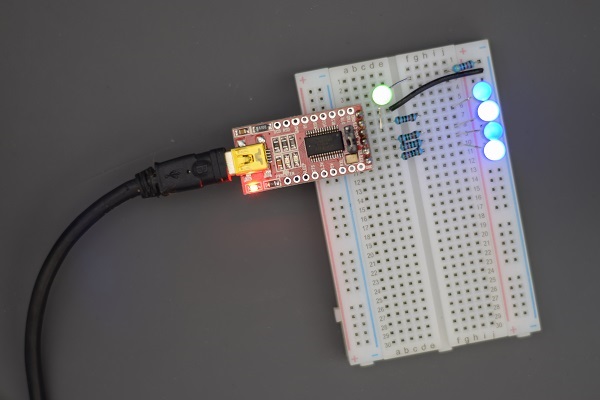
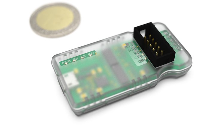
Coming soon to Crowd Supply is the ultimate USB-UART converter. μArt is a device that offers safe and reliable USB-to UART conversion. The voltage levels, electric potentials, and communication speeds are no longer a concern, and it can be used for data exchange or for Programming Arduino or ESP. μArt was designed for enthusiasts and professionals and for users in general who want to save money, time, and hardware without compromising quality.

The device has the size of two coins and was designed to tolerate user’s mistakes without getting damaged or damaging the connected hardware.

The device features a working voltage of 1.8 to 5.4, up to 3 Mbaud transfer speed, complete galvanic isolation, reverse polarity protection, pullups on all inputs, voltage autosensing, cross platform support, GPIO pins, LEDs etc. The complete features can be found on this website.

All characteristics mentioned before make it perfect for working with computers, microcontrollers, FPGAs, and low power electronics. Also, it is fast enough for transferring high quality stereo audio.

The safety features protect your computer and other hardware, and it protects the device even if you mix up the power pins.

μArt also includes characteristics that make it more efficient. It helps avoid noise because of the filters and isolation and the converter will automatically use the correct voltage levels for UART communication.

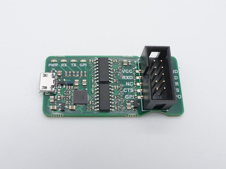
Regarding design, the device its very user friendly and many features were added to avoid mistakes. For example, the four LEDs indicate power, RX/TX activity and feedback about the connected device, it also has readable labels which minimize user errors. It is compact and comes with a transparent case that give mechanical and electrical protection. Finally, μArt has cross platform support with drivers for Windows, Linux, MacOS etc.

All of this in a small device that provides reliable and safe functionality. The device will probably be a success when it launches in crowd supply, but we have yet to see how it performs and all the applications that it will have. There is still no date for the launch, but you can sign up to be notified when it does in the crowd supply website.

UPDATE 08/08/2018: The campaign is launched on crowdsupply and back is starting from 32USD.

EMB-2610 Pico-ITX SBC Runs Linux and comes with Touch Panel

Ohio based company, Estone Technology (AKA Habey) has updated the product page for the new EMB-2610 Pico-ITX SBC. The EMB-2610 follows earlier Habey Pico-ITX SBCs such as last year’s i.MX6 UL powered EMB-2200 and i.MX6 based EMB-2230. This time Estone has used a 14nm Intel Atom SoC. Rather than going with Apollo Lake, they used the quad-core, 1.92GHz Atom x5-Z8350 from the Cherry Trail family that tried but failed to win market share in Android phones.

Estone EMB-2610 board

The Atom x5-Z8350 is the same SoC used by Aaeon’s UP Core. Like the UP Core, the 100 x 72mm, Pico-ITX form factor EMB-2610 supports Windows 10 and 10 IoT in addition to Android and various Linux distributions. The new EMB-2610 is available with 2GB or 4GB of DDR3L RAM and comes with a microSD slot and up to or 64GB NAND flash. WiFi/Bluetooth connectivity is available, as well as a GbE port with optional Power-over-Ethernet (PoE), enabled via an add-on board.

The EMB-2610 is further enhanced with a micro-HDMI port, as well as LVDS, eDP, or MIPI-DSI, all supported via a touch controller. There’s also an audio header and MIPI-CSI. USB 3.0 and 2.0 host ports are ready along with a micro-USB port, and there’s a smattering of serial, GPIO, and USB headers.

This board uses the same 40-pin expansion header found on the i.MX6-based EMB-2230. The connector, which supports optional Estone modules for 8x GPIO, front panel controls, PCIe, and PoE, is available with header specs and diagrams to make it easy to develop custom expansions. Although, the use of the connector PCIe disables the GbE port.

Specification summary for EMB-2610:

  • Processor : Intel Atom x5-Z8350 (4x Cherry Trail cores @ 1.44GHz / 1.84GHz burst); Intel HD 400 Graphics (200MHz/500MHz)
  • Memory & Storage:
    • 2GB or 4GB DDR3L
    • 32GB or 64GB NAND flash
    • MicroSD slot
  • Wireless: WiFi/Bluetooth module
  • Networking: GbE port with optional PoE
  • Media I/O:
    • Micro-HDMI port at 1920 x 1080
    • 24-bit LVDS, eDP, or MIPI-DSI at 1920 x 1200
    • An I2C capacitive touch controller
    • MIPI-CSI
    • Audio header with line-out, mic-in, headphone, 10W speaker
  • Other I/O:
    • USB 3.0 host port
    • USB 2.0 host port
    • USB 2.0 header
    • RS232
    • RS232/485 via terminal block
    • 4x GPIO
    • Micro-USB 2.0 port
    • RS232
    • RS232/485 via terminal block
    •  4x GPIO
    • 2x I2C (for TP and MIPI-CSI)
  • Expansion: 40-pin connector with PCIe x1, GPIO, front panel control, PoE input
  • Power: 12V/19V DC header or optional PoE
  • Operating temperature :  0 to 50°C
  • Dimensions : 100 x 72mm; Pico-ITX form factor
  • OS Support: Linux, Android 5.1, Windows 10 and 10 IoT

No pricing or availability information was provided for the EMB-2610 SBC. More information may be found on Estone Technology’s EMB-2610 product page.

FTDI USB-to-serial converters to drive SPI devices

Scott W Harden writes:

The FT232 USB-to-serial converter is one of the most commonly-used methods of adding USB functionality to small projects, but recently I found that these chips are capable of sending more than just serial signals. With some creative programming, individual output pins can be big-banged to emulate a clock, data, and chip select line to control SPI devices.
This post shares some of the techniques I use to bit-bang SPI with FTDI devices, and some of perks (and quirks) of using FTDI chips to bit-bang data from a USB port.

FTDI USB-to-serial converters to drive SPI devices – [Link]

SPIDriver – A better SPI Adapter

This moment in Crowd Supply you can find SPIDriver an intuitive tool for using SPI devices. The campaign that has already collected over $1000 of its $2700 goal, was designed to launch into the market a device to make our lives easier. It can be used with any SPI device such as LCD panels, flash memory, sensor LEDs etc. but what does it does exactly? The SPI driver shows you the SPI bus in real time, which is useful for debugging, testing, and calibrating.

It works with Windows, Mac, and Linux, and it can be controlled via the command line, python 2 or 3, C and C++, or a GUI. It is easy to plug in and includes 3.3 and 5 v supply. The display shows you what it’s happening in real time and sustains SPI transfers at 500 kbps. Additionally, it measures only 61 mm x 49 mm x 6 mm. Also, it uses a FTDI USB serial chip to talk to the PC.

Some of the solutions used as an example in the Crowd Supply webpage are:

  • Driving, testing, and evaluating new displays. Using displays is often difficult and getting them to work can be hard, but this device makes it easy
  • Programming SPI flash. Reading and writing SPI flash in- circuit. For example, for Atmel´s flash, a short script is everything you need to read and write
  • Lightning up LED strips. SPIDriver makes using these devices fast and fun giving users the ability to rapidly test using its own power supply

Plus, the colors in the screen are the same colors as in the cables, so you can know exactly what you are seeing.

The PCB is being manufactured by JLCPCB in Shenzhen, and its assembled in Pescadero USA. The units are thoroughly tested and calibrated with 1% accuracy.

There are 28 days left on the campaign, and you can support it with $27, $57 or 69$ which will get you your own SPIDriver (and some other stuff depending on the amount you pledge). The company claims that they will start delivering rewards on August 24th.

This device was designed, so that you never have to ask yourself again “What’s it doing now?”, and its meant to be used by all kinds of people from total beginners to experts. The complete specifications can be found on this website which is also the place to back the project.

Firefly’s Latest Core-PX3-SEJ COM Runs Ubuntu or Android

Firefly has launched a new SODIMM-style, 67.6 x 40mm Core-PX3-SEJ module that runs Android 5.1 or Ubuntu 15.04 on a Rockchip PX3-SE. It’s a new 1.3GHz, quad-core, Cortex-A7 SoC. The 40 USD module is available in a 1GB RAM/8GB eMMC configuration on a $120, 117 x 85mm Firefly-PX3-SE development board. Other memory configurations may also be available soon.

Firefly Core-PX3-SEJ module

The PX3-SE SoC gives the module a sandwich-style dev board and increases the operating temperature to -20 to 80 range. The Core-PX3-SEJ module is praised for its anti-corrosion gold finger expansion connector, and the dev board for its “double stud fixed” design.

Rockchip’s PX3-SE SoC was announced in May 2017. The main target of this SoC is Linux and Android-driven “mobile vehicle interconnect solutions.” The quad-A7 SoC implements a Mali-400 GPU and supports HD video.

The Firefly-PX3-SE board’s 2.4GHz WiFi and Bluetooth 4.0 are supplied separately from the compact Core-PX3-SEJ COM. Despite the lack of 4K support, there are a numerous media interfaces, including a variety of audio features. There are HDMI, CVBS, MIPI-DSI or LVDS, and a DVP camera interface. Analog, SPDIF, and I2S audio connections are available along with an onboard mic and a “phone” I/O port.

The Firefly-PX3-SE board is further provided with a GbE port, 4x USB 2.0 host ports, a micro-USB OTG port, and an 84-pin expansion header. RTC, debug, and IR are also onboard.

Specifications summary for the Firefly-PX3-SE development board with Core-PX3-SEJ module:

  • Processor : Rockchip PX3-SE (4x Cortex-A7 cores @ 1.3GHz); Mali-400 MP2 GPU
  • Memory:
    • 256MB, 512MB, 1GB, or 2GB DDR3 RAM (via Core-PX3-SEJ)
    • 4GB to 64GB eMMC flash (via Core-PX3-SEJ) with 4GB and 8GB default SKUs
    • MicroSD slot
  • Wireless:
    • 2.4GHz 802.11b/g/n with antenna
    • Bluetooth 4.0 with BLE
  • Networking: Gigabit Ethernet port (Realtek RTL8211E)
  • Display & media:
    • HDMI port with audio
    • MIPI-DSI or LVDS LCD interface
    • CVBS with video and audio
    • DVP camera interface for up to 5MP
    • 3.5mm analog audio input jack
    • SPDIF optical output
    • Microphone input
    • I2S audio I/O
    • A phone I/O interface
  • Other I/O:
    • 4x USB 2.0 host ports
    • Micro-USB 2.0 with OTG
    • Serial console debug
    • 84-pin expansion header (MIPI, LVDS, PWM, SPI, UART, ADC, I2C, I2S, GPIO)
  • Other features: RTC with battery; IR receiver; power, reset, recover buttons; acrylic rack kit
  • Power: 5V, 2A (via DC jack); PMU (via Core-PX3-SEJ)
  • Dimensions: 117 x 85mm (with 67.6 x 40mm integrated COM)
  • OS Support: Android 5.1; Ubuntu 15.04; includes Linux Buildroot/Qt

The Core-PX3-SEJ module and Firefly-PX3-SE development board are available for $80 and $140 (including module), respectively, plus shipping. More information may be found at Firefly’s Core-PX3-SEJ and Firefly-PX3-SE shopping pages.

PIC18 Q10 Product Family – PIC® MCUs for Closed-loop Control

Real-time control systems usually are closed-loop control systems where one has a tight time window to gather data, process that data, and update the system. If the time window is missed, then the stability of the system is degraded. This reduced control can be catastrophic to some applications, such as power conversion and advanced motor control. Many semiconductor companies are claiming their MCUs can support real-time control applications, but they don’t usually offer an accurate real-time control system. Microchip has unveiled a new PIC18 Q10 family featuring multiple intelligent Core Independent Peripherals (CIPs) that help designers to simplify development and enable quick response time to system events.

Microchip which in 2016 acquired Atmel, the company famously known for the Atmega 328P, the microcontroller behind the Arduino Uno has launched a set of microcontrollers that are tailored for real-time control system called the PIC18 Q10 Family of Microcontrollers. The new family is designed for a robust system with intelligent analog, configurable peripherals and operates at 5V, making it ideal for noise prone applications because 5V offers more noise immunity as compared to 3.3V MCUs.

The PIC18 Q10 family of MCUs features CIP (Core Independent Peripherals) that provide the ability to accomplish tasks in hardware while freeing up the Central Processing Unit (CPU) to do other tasks or go to sleep to save power. The hardware-based peripherals offload timing-critical and core-intensive functions from the CPU, allowing it to focus on more complex functions within the system. This decreases system complexity by eliminating additional code and external components, reduces power consumption, allowing for deterministic response time as well as decreased validation time.

The family is made up of about seven different MCUs all coming in different package type from DIP to a QFN, making it ideal for space-constrained closed-loop control system while still applicable for hobbyist and enthusiast by leveraging on the DIP package version. The products offer Intelligent Analog peripherals including Zero Cross Detect (ZCD), on-chip comparators and a 10-bit ADC with Computation (ADC2) automating Capacitive Voltage Divider (CVD) techniques for advanced touch sensing, averaging, filtering, oversampling and automatic threshold comparison.

These are some of the PIC18 Q10 Key attributes to take note off:

  • 64 MHz internal oscillator
  • Up to 128 KB Flash program memory
  • Up to 1 KB data EEPROM
  • Up to 3615 B data SRAM
  • 10-bit ADC2 (ADC with Computation), up to 35 channels
  • Four 16-bit timers
  • Complementary Waveform Generator (CWG)
  • Two comparators
  • Zero Cross Detect (ZCD)
  • Windowed Watch Dog Timer (WWDT)
  • Peripheral Pin Select (PPS)
  • Data Signal Modulator (DSM)
  • Up to 8 Configurable Logic Cells (CLC)
  • 5-bit DAC
  • EUSART, SPI, and I2C
  • Available in 28-, 40- and 44-pins

The PIC18 Q10 family can be used with the curiosity development boards which are cost-effective MCU development platforms and can be used to accelerate the development of the MCUs family. The family is also supported by MPLAB® Code Configurator (MCC), a free software plug-in that provides a graphical interface to configure peripherals and functions specific to your application.

Based on its overwhelming featuers, the PIC18 Q10 family is suited for a broad range of applications including industrial control, consumer, automotive, touch sensing, advanced motor control, and the Internet of Things (IoT). More information about the product family can be found on the product page.

Humidity Sensor for Battery-Driven Applications

Sensirion, the expert in environmental sensing, presents the new ultra-low power humidity sensor SHTC3 for mobile and battery-driven applications. The SHTC3 is a digital humidity and temperature sensor optimized for battery-driven applications and high-volume consumer electronics. The sensor has been designed to overcome conventional limits in size and power consumption in order to fulfill current and future requirements, and offers an unmatched performance-price ratio. The SHTC3 improves the performance and flexibility of the SHTC1, while maintaining its proven reliability.

Sensirion’s CMOSens® Technology offers a complete sensor system on a single chip, consisting of a capacitive humidity sensor, a bandgap temperature sensor, analog and digital signal processing, A/D converter, calibration data memory, and a digital communication interface supporting I2C fast mode. The small 2 x 2 x 0.75 mm3 DFN package enables applications in even the most limited space. The sensor covers a humidity measurement range of 0 to 100% RH and a temperature measurement range of -40°C to 125°C with a typical accuracy of ±2% RH and ±0.2°C. The broad supply voltage of 1.62 V to 3.6 V and an energy budget below 1 μJ per measurement make the SHTC3 perfectly suited to mobile or wireless applications powered by battery.

With the industry-proven quality and reliability of Sensirion’s humidity and temperature sensors providing constant accuracy over a large measurement range, the SHTC3 offers the best performance-price ratio. Tape and reel packaging combined with suitability for standard SMD assembly processes make the SHTC3 ideal for high-volume applications.

Bode Analyzer using STM32F407 Discovery board

Debraj shares his project details of a Bode Analyzer using STM32F407. He writes:

Frequency domain analysis is very important to know more about any system/ circuit or transfer function that we deal with. And the first thought comes to our mind about frequency domain analysis is “Bode plot“. Bode plot is a combination plot of magnitude and phase difference of output vs. input of a cosine wave of single frequency, when it is applied to a circuit.

Each of these cosine wave (signal) are applied once at a time and the frequency (in Hz or rad/sec) is increased in linear order (called chirp). All the while the amplitude of sine wave is kept constant (at say 1V_peak). While the frequency can be increased in small steps (1Hz/ sec), the time required to complete the entire frequency range can be quite big. Hence, it is preferred to choose 20 frequencies/ decade. For example, I had chosen 05Hz, 1Hz, 1.5Hz, 2Hz, 2.5Hz… 10Hz.

Bode Analyzer using STM32F407 Discovery board – [Link]

ESP32- Now With Long Range Wi-Fi

Nowadays, Wi-Fi is a word we hear often, and it is a technology that we use all the time. There are around 279 million Wi-Fi hotspots in the world, and in 2021 that number is expected to increase to 542 million hotspots. The wireless nature of this technology allows users to access a network from any convenient location. Wi-Fi chipsets are pieces of hardware designed for wireless communication and they are cheap, and readily available, but the range don’t match the expectations, and configuring its coverage is no easy task.

Support for the 802.11 LR mode in the ESP-IDF was added at the end of 2016. The 802.11 LR mode can achieve a 1 km line of sight range if both the station and the Soft-AP are connected to an ESP32 device.

ESP32 is a low cost, low power system on a chip (SoC) with Wi-Fi and Bluetooth capabilities. It was created for mobile devices, wearables electronics, and for Internet of Things applications. The devices have low power consumption. The EPS32 uses Tensilica Xtensa LX6 microprocessor and it was created by Espressif systems.

The mode was included quietly, so there has not been much talk about it, but some people noticed the inclusion, and have been testing the long-range mode in the field. Enabling the mode requires only a function call, making it easy to use. The long-range mode comes with a cost which is the data rate which is significantly reduced. In addition, a lot more can be done if the common router antenna is replaced by directional antenna.

This device has already been tested by some users for drones and long-distance applications, but there is no formal data about the device’s performance, problems, and even the applications are not clear enough. The recent increase in popularity could lead to conclusive data which could make the mode more reliable.

The applications for this includes remote drone video, telemetry (collecting data at remote or inaccessible points and transmitting it for monitoring), wardriving (finding Wi-Fi hotspots from a moving vehicle) etc. There are many possibilities, but we must give makers time to figure this new mode on their own, and to test its capabilities.

[Source]

ESP8266 (ESP-03) Based Ultra Low Power Weather Logger

Yet another ESP8266 (ESP-03) based ultra low power weather logger with 4 sensors.

Features

  • Working with two AA battery
  • Ultra low power consumption
  • 4 sensors and 6 measurements:
  • HDC1080 – Temperature & Humidity
  • LPS25HB – Pressure
  • VEML6070 – Ultraviolet Index
  • TSL2561 – Ambient & Infrared
  • Built-in 3.3v Boost Converter
  • TPL5111 System Timer (20 mins update interval, can be customized via resistors)
  • Battery voltage monitor
  • UART port for programming & debugging

ESP8266 (ESP-03) Based Ultra Low Power Weather Logger – [Link]

TOP PCB Companies