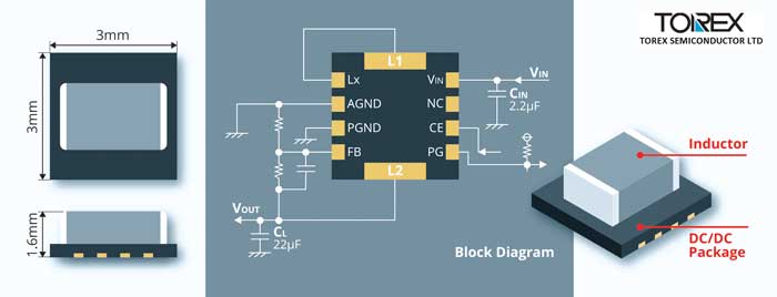
Step-down micro DC/DC converters make up the XCL225/XCL226 series from Torex Semiconductor.
The 18V coil-integrated converters contribute to space-saving on the board and a shorter development time because a circuit can be configured by simply adding two external ceramic capacitors, explains Torex. An internal coil lowers EMI and also simplifies the board layout and makes it possible to minimise radiation noise and circuit operation issues.
The package is a small DFN3030-10B, measuring 3.0 x 3.0 x 1.7mm. The maximum input voltage of 18V allows the XCL225/XCL226 to be used for a range of industrial equipment and IoT devices, including refrigerators and air conditioners. Other target applications are electronic devices, point of sale terminals, industrial equipment, and IoT devices that use two or three lithium-ion batteries or four or more dry-cell batteries.
The operating voltage range is 3.0 to 18V, and the maximum output current is 0.5A. The switching frequency is 1.2MHz. The XCL225 uses PWM control to provide minimum output ripple voltage by fixing the operating frequency. The XCL226 uses PWM/PFM auto switching control to lower the operating frequency at light loads which reduces power dissipation and realises high efficiency from light loads to heavy loads. The output voltage can be set within a range of one to 15V using external resistors, adds Torex.
Artificial intelligence (AI) is an area of computer science that works towards creating machines that could make decisions, react, and interact just like a human would. To be considered AI a computer must be capable of recognizing speech, learn, plan, and solve problems. To do all this a computer must have a way to perceive the world and even interact with it (move). This type of technology has been used for personal assistants such as Siri and Alexa, for customer prediction (Netflix and Pandora), for autonomous vehicles, gaming etc. However, one application that has not been exploited is for signal processing.
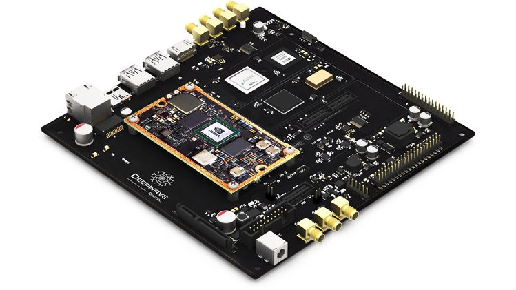
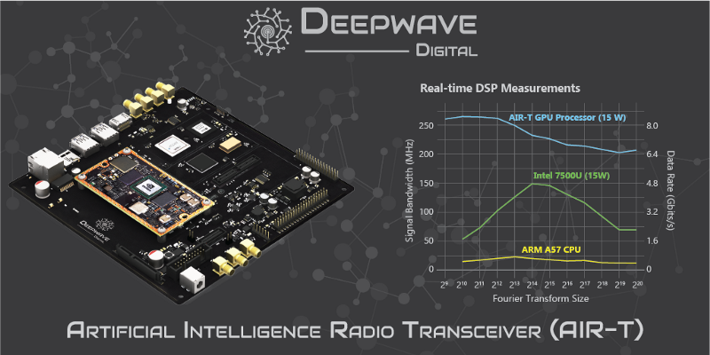
Deepwave Digital decided to be pioneers in using AI for signals. The company created the AIR-T (Artificial Intelligence Radio Transceiver) which is a high-power SBC that uses NVIDIA Jetson TX2 for signal processing and deep learning applications.
Nowadays we deal with an increasing number of signals, because of Wi-Fi and cellular communications, and the technology is still human dependent to select the correct frequencies. Because of this, the need for an AI to do the work for us has become increasingly high, and as it turns out the AI can do the work better than us.
The AIR-T board also includes Xilinx Artix 7 FPGA and an Analog Devices 9371 MIMO transceiver with two RX channels of 100 MHz and a couple of TX channels of 250 MHz for connectivity, the device includes Bluetooth, Wi-Fi, HDMI, GPIO/UART, USB 2.0 and 3.0 etc. It uses Ubuntu 16.04, and it can be programmed using Python or C++.
All these characteristics make the device adaptable to many applications which will allow users to create and shape different projects. This project gives users the ability to adapt to software defined radio. Deepwave said:
This versatile system can function as a highly parallel SDR, data recorder, or inference engine for deep learning algorithms. The embedded GPU allows for SDR applications to process bandwidths greater than 200 MHz in real-time.
The device is not yet on sale, and Deepwave is expected to launch a crowdfunding to commercialize the product in the future, so there is still no information about price or sellers.
The idea is to redefine how signal processing is done using machine learning.
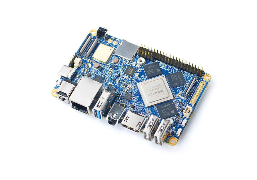
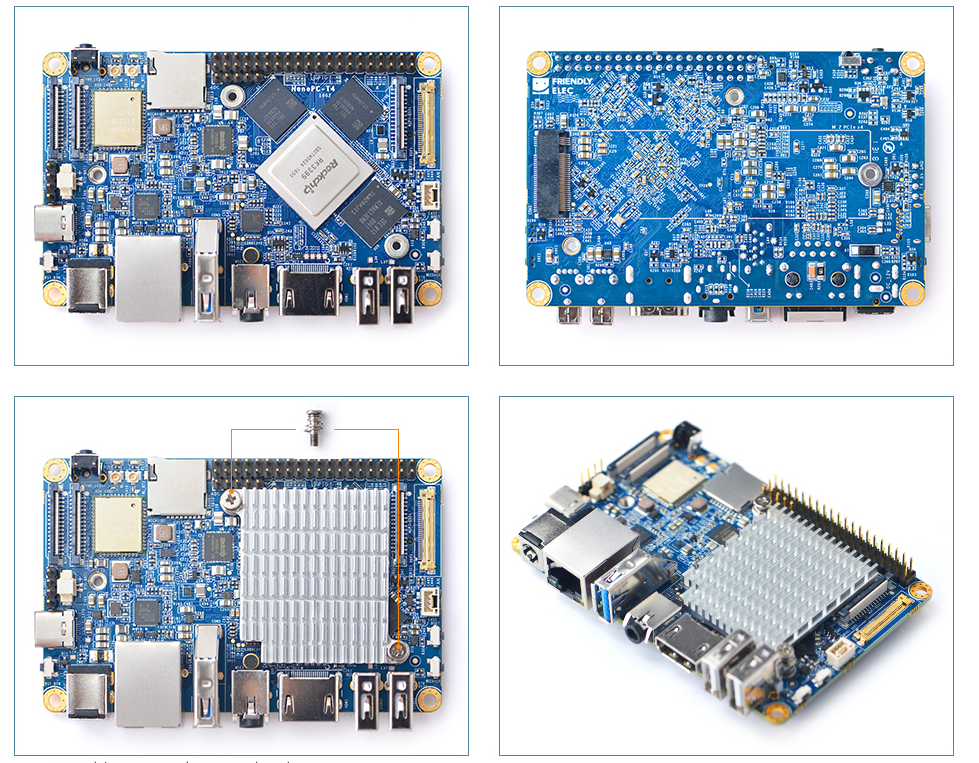
FriendlyElecrecently released a pretty exciting hacker board which is super cheap, considering the features of the board and the price it is being sold for. The Single Board Computer (SBC) is based on Rockchip RK3399; a low power, high-performance processor. The board which is called Nano PC – T4 can be regarded as the smallest rock chip based board as it measures 100mm by 64m as compared to other RK3399 SBCs. It is different from other Nano Pi, and Nano PC SBCs produced by FriendlyElec because previous boards run on Samsung of Allwinner System on Chips (SOCs).
NanoPC-T4
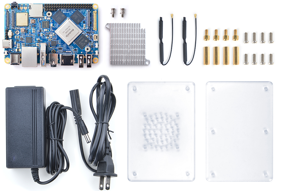
The board comes with a default 4GB RAM and a whopping 16G eMMC (embedded Multi Media Card). It also works with Android 7.1 which can be exchanged for the full fledged Lubuntu Desktop version of Ubuntu. Nano PC – T4 uses the same system-on-a-chip (SoC) as Samsung’s Chromebook Plus but at a lesser price. Other features are 16 GB storage onboard bundled with a heatsink, radio antennas, a power adapter, and an acrylic case. The RK3399 SoC supplies two Cortex-A72 cores that are clocked at up to 2.0GHz, and an additional four Cortex-A53 cores clocked to 1.5GHz. There’s also a high-end ARM Mali-T864 Graphics Processing Unit (GPU) included into the device.
The board comes with an M.2 2280 connector, which allows high-speed PCIe SSDs to be used, the M.2 connector supports PCI Express 2.1, that has been wired for x4, making it possible to get I/O speeds at a very fast speed. On the other end, we have the Firefly-RK3399, which is being sold for $149 with a 2GB RAM or $209 with a 4GB RAM. Another board is the Orange Pi which goes for $109 and has a 2GB RAM. Unlike the expensive Orange Pi RK3399, the NanoPC-T4 gives a wider 0 to 80℃ temperature range, ADC interfaces, DDR4 instead of DDR3 RAM, and twice the amount of RAM for the oversight configuration.
Below are some of the device’s specifications:
Processor — Rockchip RK3399 (2x Cortex-A72 at up to 2.0GHz, 4x Cortex-A53 @ up to 1.5GHz); Mali-T864 GPU
Memory:
4GB LPDDR3 RAM (dual-channel)
16GB eMMC 5.1 flash
MicroSD slot
Optional NVME SSD via M.2 M-Key (see expansion section below)
Media:
HDMI 2.0a port (with audio and HDCP 1.4/2.2) for up to 4K at 60Hz
DisplayPort 1.2 (via USB Type-C)
MIPI-DSI (4-lane)
eDP 1.3
2x, 4-lane MIPI-CSI (up to 13MP) with dual ISP support
3.5mm analog audio I/O jack
Wireless:
802.11b/g/n/ac 2.4GHz/5GHz dual-band
Bluetooth 4.1 dual mode
Dual antennas
IR receiver
Networking — Gigabit Ethernet port
Other I/O:
USB 3.0 host port
USB 3.0 Type-C port (can be used for DP)
2x USB 2.0 host ports
Serial debug UART
3x ADC (1.8V)
12V cooling fan interface with PWM
Expansion:
40-pin RPi compatible expansion header
M.2 M-Key slot with PCIe 2.1, dual operation mode, and M3 PCB nut for mounting M.2 2280
Other features — RTC; power, reset, recovery, boot buttons; LEDs; heatsink; acrylic case
Power — 12V/2A DC input jack and adapter; PMIC
Operating temperature — 0 to 80℃
Weight — 63 gm
Dimensions — 100 x 64mm; 10-layer PCB
Operating system — Android 7.1.2; Lubuntu Desktop 16.04
One major taking point for the NanoPC-T4 is the availability of two MIPI-CSI x2 making it a dual camera interface platform. This simultaneous dual camera data support is going to make the device ideal for VR and AR applications. The NanoPC-T4 has four high-performance display interfaces (DP 1.2 @60fps, HDMI 2.0, MIPI-DSI @60fps, and eDP 1.3) on a small board and supports dual display output.
Despite the fact that the board does not have an HDMI input port or even built-in sensors, the Nano PC – T4 has a wide range of applications, some of them are advertisement machines, game machines, video conferencing, clusters, surveillance and many more. It also supports certain advanced features such as native GbE and a dual purpose USB Type C port serves as the display port.
The NanoPC-T4 is available for purchase online at a discounted price of $129 and can be bought on the product page here. The board purchase comes in a complete package. Below are some of the items present in the item package:
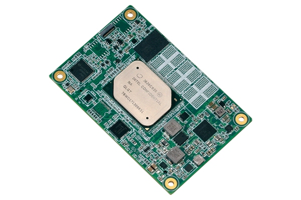
(Taipei, Taiwan – June 12, 2018) – AAEON, a world-leading developer of embedded controllers and industrial solutions, launches the NanoCOM-APL, a machine vision and factory automation-focused Type 10 COM express module with onboard support for dual MIPI CSI interfaces.
The NanoCOM-APL is built around a 6th Generation Intel® Atom™, Celeron®, or Pentium® processor and features onboard LPDDR4 memory with a capacity of up to 8GB. The 7W module’s low power-consumption architecture means it can be used at the heart of hand-held, battery-powered devices and fully enclosed IP67 applications.
“Combined with an FPGA controller and an AI chip, the NanoCOM-APL is being used as the centerpiece of advanced machine vision systems that scan products to create 3D images that can be checked for faults,” noted David Hung, AAEON embedded computing division product specialist. “Because of its size and industrial operating temperature range, these systems can be used on a production line or even on a robotic arm.”
The module also features 1GbE LAN connections, optional onboard eMMC storage of up to 64Gb, a PCIe [x4] expansion slot, an LVDS, DDI, or eDP connections, and support for up to eight USB3.0 and two USB2.0 ports.
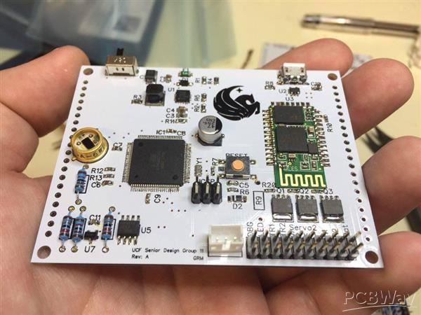
After making your PCB prototype the significant next step is placing your components on the printed circuit board. Depending on the sophistication of the prototype being developed, the number of parts to be used, and the parts layout; one might want to solder the components to the PCB board manually.
Soldering components to a PCB might be a good idea, but might not be that efficient or even cheaper in the long run. Not only this will be an avenue to waste precious time especially when dealing with more than five boards, but it is too prone to errors. A single mistake on the board might render the whole board useless. Just like we have seen PCB making services, there is also PCBA (Printed Circuit Board Assembly) services available that can solve this.
One of the primary reason people go the route of assembling their printed circuit boards by hand is that of the cost associated with it doing PCBA. PCBA services have been traditionally known to be expensive for people making prototypes because they tend to order only small units. I remember my first PCBA job for about two units that cost me over $500 to finish. PCBA is usually ideal when one wants to embark on medium to large scale manufacturing but not small batch. PCBWay is hoping to bring change to this space, by offering PCB Assembly wholly tailored for prototypes and small batch quantities, and also comes with some exciting incentives as well.
PCBWay.com is a China Shenzhen-based manufacturer specializing in PCB prototyping, low-volume production, and PCB Assembly services under one roof. PCBWay has been one of the go-to destinations for boards fabrication and assembly, and they have over 71K active customers worldwide using their services. PCBWay offers PCBA services that specialize in the prototyping and small batch printed circuit board assembly at a relatively low cost as compared to others.
PCBWay is offering unbelievable pricing for their Prototype PCBA services. Their prototype PCBA rates are starting from $88 for 10 pcs in total and $0.1 – $0.3 per component cost. Not only are this prices low, but they are also going to bring down the barriers to making prototypes and reduce the time to market.
Mounting BGA, Micro-BGA, QFN and leadless package parts are some challenging tasks for PCBA, and where some manufacturers have somewhat abstained from. PCBWay is fully able to handle any of those parts without issues and they can handle BGA of 0.25mm pitch with X-ray testing. The following are some of the PCBWay Printed Circuit Board Assembly capabilities:
SMT Assembly
BGA Assembly
Through Hole Assembly
Mixed Assembly
Rigid Flex PCB Assembly
Aside from the Printed Circuit board assembly, PCBWay also provides options for outsourcing your PCB parts called Turn-Key options. For the PCB Assembly, the following are the board requirements:
Min Board Size: 50mm x 100mm (Boards smaller than this size need to be panelized)
Max Board Size: 250mm x 500mm
In addition to the low cost of the PCBA services, PCBWay is also providing options for free shipping all around the world, free stencil, quality check & guarantee, and many others. To get started with the PCBWay you can visit their website here.
Hi guys, today, I will show you how to use a servo motor with an Arduino. This tutorial is ideal for beginners because it is easy and it gives them the foundation to build interesting projects like robots for which servos are commonly used.
Servo motors are high torque motors which are commonly used in robotics and several other applications due to the fact that it’s easy to control their rotation. Servo motors have a geared output shaft which can be electrically controlled to turn one (1) degree at a time. For the sake of control, unlike normal DC motors, servo motors usually have an additional pin asides the two power pins (Vcc and GND) which is the signal pin. The signal pin is used to control the servo motor, turning its shaft to any desired angle.
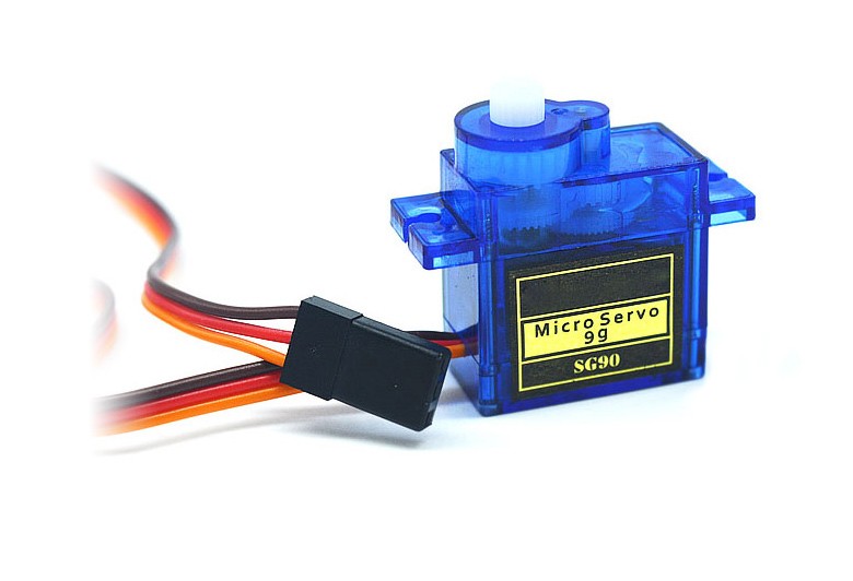
SG90 Servo motor
For this tutorial, we will be using the popular SG90 servo motor and our goal will be to rotate the servo motor from one end to the other.
Servo’s have high current requirement so when using more than one servo motor with the Arduino, it is important to connect their power connections to an external power supply as the Arduino may not be able to source the current needed for the servo. Since we will be using just one servo in this tutorial its fine to power it with an Arduino.
Required Components
The following components are required to build this project:
Each of these components can be bought via the link attached to them.
Schematics
The schematics for this project is quite simple as we will be connecting just the servo motor to the Arduino.
Servo motors generally have three pins/wires, this includes the VCC, GND, and the Signal pin. The Signal pin is the one used to feed the control signal from the microcontroller to the servo, to get the servo rotate to a particular angle.
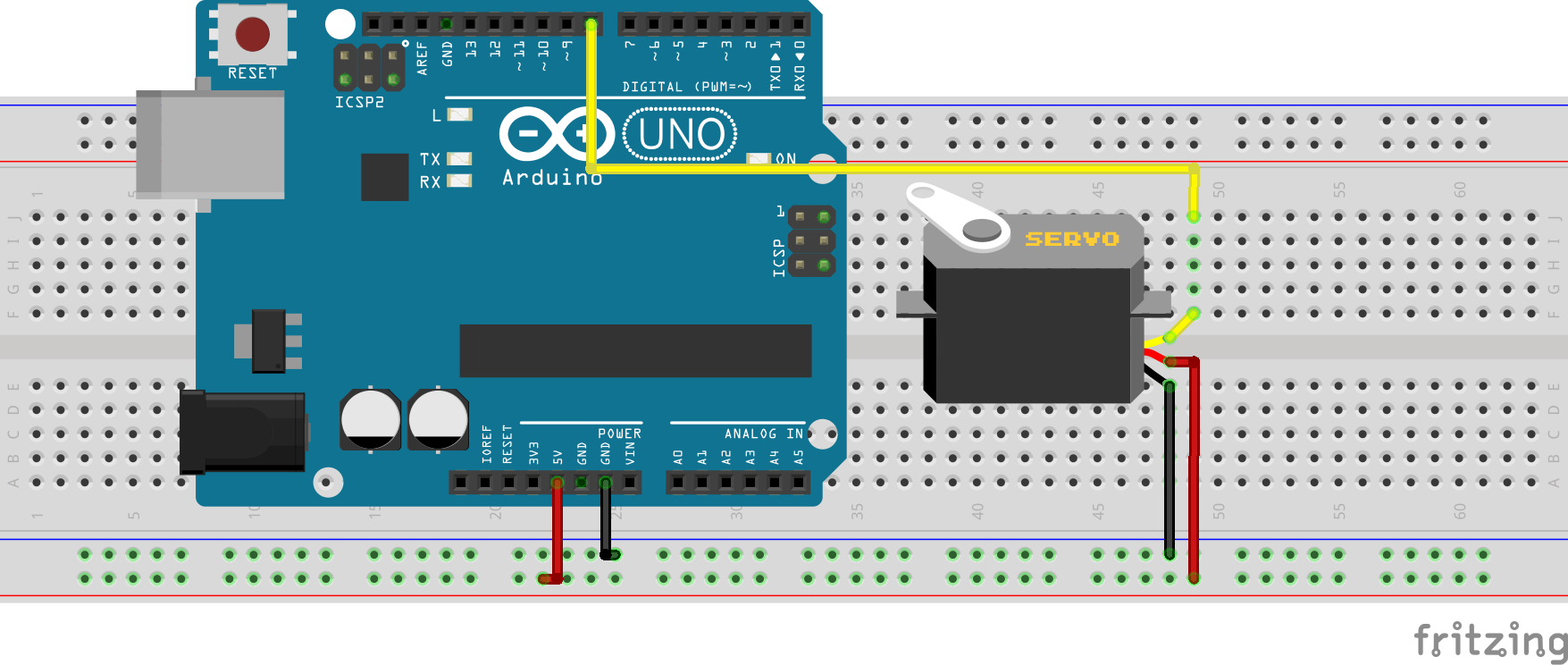
Connect the Servo to the Arduino as shown in the schematics below.
Schematics
For emphasis, the connection is further described below.
The signal pin was connected to the digital pin 8 of the Arduino because it is a PWM pin. Servo directions are sent from the microcontroller to the servo motor as PWM pulses.
With the connection all done, we can now proceed to write the code for the project.
Code
The code for this project is quite easy thanks to the very comprehensive and concise servo.h library developed by the Arduino team to facilitate the use of servo motors in Arduino projects. The library makes it easy to turn the servo at different angles using a single command. The library comes pre-installed in the Arduino IDE removing the need for us to download and install.
We start the code for the project by including the libraries that we will use which in this case is the servo.h library.
#include <Servo.h>
Next, we create an object of the library, to be used as a reference for controlling our servo motor throughout the code.
Servo servo;
With this done, we proceed to the void setup() function. we start the function by attaching the servo object created to pin D8 of the microcontroller, after which we center the servo, turning it to zero degrees.
With that done, we are ready to move the servo in any direction we desire, and we will be doing this under the void loop function. Thanks, to the servo.h library all we need to do, to rotate the servo to an angle we desire, is to pass the desired angle as an argument into the servo.write() function. To demonstrate this, a for-loop was used to turn the servos at several angles in one direction and another loop was used to turn the servo back to where it started.
void loop()
{
// scan from 0 to 180 degrees
for(angle = 10; angle < 180; angle++)
{
servo.write(angle);
delay(15);
}
// now scan back from 180 to 0 degrees
for(angle = 180; angle > 10; angle--)
{
servo.write(angle);
delay(15);
}
}
The complete code for the project is available below and can be downloaded from the download section at the end of the tutorial.
#include <Servo.h>
Servo servo;
int angle = 10;
void setup() {
  servo.attach(8);
  servo.write(angle);
}
void loop()
{
 // scan from 0 to 180 degrees
  for(angle = 10; angle < 180; angle++)
  {
    servo.write(angle);
    delay(15);
  }
  // now scan back from 180 to 0 degrees
  for(angle = 180; angle > 10; angle--)
  {
    servo.write(angle);
    delay(15);
  }
}
Demo
Copy the code above and upload to your Arduino and servo motor setup, after a few time, you should see the servo motor start turning as shown in the gif below.
Demo
That’s it for this tutorial guys, the code above can be expanded in several ways for use in different projects involving servo motors, what cool thing will you be building with the servo motor? feel free to share via the comment section.
The video tutorial for this project can be watched on youtube.
Earlier this month, Google released Android Things 1.0 and announced many consumer products that will ship in the coming months based on the stripped-down, IoT-oriented Android variant. Google uncovered four ARM-based production boards for Android Things 1.0: Innocomm’s i.MX8M based on WB10-AT, Intrinsyc’s Open-Q 212A and Open-Q 624A, based on the Snapdragon 212 and 634, respectively, and the MediaTek MT8516.
The most important news with the first market-ready release of Android Things is that Google is offering free OTA security and patch updates for three years to all targeted devices. However, Google needs a licensing deal to deploy more than 100 commercial systems using the OTA updated long-term version of Android Things, and the OS itself is “managed” and tightly controlled by Google.
The modules share the same small footprints of about a 50 x 50mm. They also focus on audio features that might support integration with the Google Assistant voice agent. The first round of consumer devices using Android Things are smart speakers and automation hubs that integrate Google Assistant.
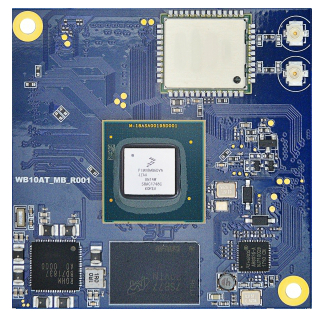
WB10-AT
InnoComm Google WB10AT COM
InnoComm’s 50 x 50mm WB10-AT COM is almost identical to the WB10 module announced in March. The only difference except for the OS is that the AT version ships with 1GB LPDDR4 instead of 2GB. The WB10-AT includes a 1.5GHz, Cortex-A53 based NXP i.MX8M Quad SoC with a 266MHz Cortex-M4 core. It extends 8GB eMMC, 802.11ac, Bluetooth 4.2, and a GbE controller.
The WB10-AT allows HDMI 2.0 with 4K HDR support, as well as extensive audio I/O enabled by the audio-savvy i.MX8M. Audio specs include 4x SAI, DSD512, and S/PDIF.
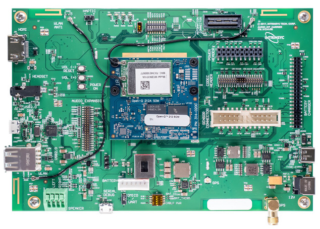
Open-Q 212A Development Kit
Open-Q 212A board and module
Intrinsyc’s Open-Q 212A is a sandwich-style SBC designed for next-gen smart speaker and voice-controlled home hub products. There is a new 50 x 46.5mm Open-Q 212A Android Things SOM with a quad-core, Cortex-A7 Qualcomm Snapdragon 212 (SDA212) — the lowest-end SoC available for Android Things mounted on a 170 x 115mm carrier board.
The new module provides 1GB LPDDR3, 4GB eMMC, WiFi-ac, and BT 4.2. The 12V carrier board adds 2x USB host ports, a micro-USB client port, and a micro-USB debug port. It also includes a MIPI-CSI and MIPI-DSI interfaces, with the latter capable of up to 720p LCD displays. PCB antennas are also available.
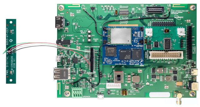
Open-Q 624A Development Kit
Open-Q 624A
This new sandwich-style kit is Google’s high-end Android Things platform. It connects a new Open-Q 624A Android Things SOM and carrier board, each of which is the same size as their Open-Q 212A counterparts.
The module extends 2GB RAM, 4GB eMMC, WiFi-ac, BT 4.2, and a new, undocumented octa-core Snapdragon 624 SoC based on the existing Snapdragon 625. Like the Snapdragon 625, the 624 provides 8x Cortex-A53 cores at up to 1.8GHz along with an Adreno 506 GPU with support for 4K @ 30fps video. Google calls the Snapdragon 624 the SDA624, and in one place Intrinsyc refers to it as the APQ8053, which is also the name of the Snapdragon 825.
The Open-Q 624A carrier board has a feature set that is very similar to that of the similarly sized Open-Q 212A board. However, it adds a USB 3.0 Type-C port, sensor expansion and haptic output, and an optional GPS receiver, which like the module’s WiFi and Bluetooth, is available with an antenna.
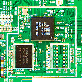
MediaTek MT8516
MediaTek MT8516
Google refers to the MT8516 as a virtual SoM, as opposed to the other physical modules, and suggests that the module’s capabilities are directly integrated into a reference board designed for high volume applications.
Whatever the form factor, the MT8516 provides a quad-core, 1.3GHz Cortex-A35 processor with 4GB eMMC, WiFi, BT, and RF. The platform is intended for voice assistance and other audio applications and provides 4-channel I2S x2, 8-channel TDM, and 2-channel PDM input for voice input control and connected audio.
The Cortex-A35 cores draw about 33 percent less power per core and occupy 25 percent less silicon area than Cortex-A53. The -A35 design lies at the heart of NXP’s i.MX8X SoC, which is also available in two dual-core models. The i.MX8X is found on Phytec’s phyCore-i.MX 8 module.
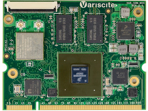
Variscite a leading SOC manufacturer from Israel, has released a new version of its wireless-enabled “VAR-SOM-MX6” module. It adds support for the i.MX6 QuadPlus SoC. Variscite is renovating the old COM once again with a model that adds support for NXP’s QuadPlus. It is going to be a new addition to the i.MX6 Solo, DualLite, Dual, and Quad versions. The module runs Linux 4.9.11 and Android 8.0 (Oreo).
VAR-SOM-MX6 module with QuadPlus support
The i.MX6 QuadPlus, which is also available on the Wandboard Reload SBCs, iWave’s i.MX6 COMs, and other boards. It has the same, 1.2GHz quad-core CPU as the Quad, but offers an enhanced Vivante GC2000+ GPU with 50 percent elevated graphics performance. The SoC also provides HD-resolution H.264 decode and encode.
The 2018 version of the VAR-SOM-MX6 is identical with the pin configuration as the earlier models. It has up to 4GB DDR3 RAM and data storage of 4GB to 64GB via eMMC and 128MB to 1GB NAND flash. There’s a GbE controller, although with the usual i.MX6 bandwidth limits. The 802.11n WiFi, which is accompanied by Bluetooth 4.1 with BLE, is available with optional 2×2 MIMO.
The 67.8 x 51.7mm module houses dual 24-bit LVDS interfaces with resistive touch, as well as an HDMI and DSI interfaces. The long list of peripherals includes dual CAN, SATA, PCIe, MIPI-CSI, and much more support. The module has a range of -40 to 85°C working temperatures.
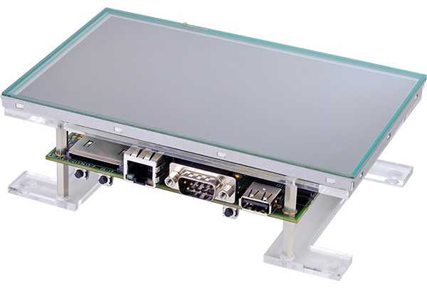
VAR-SOM-MX6 eval kits
VAR-SOM-MX6 Development Kit
The $399 VAR-SOM-MX6 Starter Kit includes the carrier board with the VAR-SOM-MX6 module, an antenna, a debug cable, a microSD card, and a carrier board design package. The $499 Development Kit version adds a 12V power supply, an Ethernet cable, and a 7-inch resistive touch panel. The $549 Development Kit Pro advances to a 7-inchcapacitive touchscreen.
The VAR-SOM-MX6 module with QuadPlus support is available now starting at $52 per unit in volume. The development kits start at $399. More information may be found in Variscite’s VAR-SOM-MX6 with the QuadPlus announcement and product page.
A lot of makers have started venturing into the wearable world in which everything is portable, invisible, light, flexible and functional. Many have found that using Arduino compromised two of those characteristics. Arduino is not flexible, and it is not invisible which is why it is hard to incorporate into this kind of projects.
NextFlex in Silicon Valley has created a prototype of a flexible Arduino, based on the Arduino mini. The prototype is printed on a polymer and then the standard components are bonded. This means that the device is not yet completely flexible since it includes some rigid components, but the company hopes that in the future components such as resistors and capacitors would be printable too.
The process for making the flexible Arduino involves automated screen printers and industrial inkjet printers for printing the circuit on a 1mm thick flexible plastic board. Then, the microcontroller silicon die is connected directly into the surface with high precision.
The conductive ink used is an advanced formulation of silver ink with bending and flexing capabilities, and with strong adhesion to the surface. The ink is not new in the market, but the company is working toward making more reliable and resilient materials.
This device could bring wearables to a whole new level of comfort and could also be used in a lot of situations such as when space is an important variable, or when weight could affect the correct functioning of the device. As a result, the device would not only be useful for makers, but also for students, product designers etc.
On June 26 of the current year, NextFlex will be taking about the project at the Sensors Expo & conference in San Jose, California.
Manufacturers think that prices in this kind of technology would drop rapidly, making it accessible for everyone to use on their projects. NextFlex wants to make this kind of technology the new mainstream for all kind of projects. Flexible microcontrollers could also be used in IoT and medical applications.
In conclusion, Arduino is already a beloved microcontroller because of its open source hardware and software, its ability to be easily programmed, and its low cost, but now it could also be known because of its practical presentation, and ability to be blended. This device is just a prototype and we should expect improvements in the future, but the future is looking bright for makers.
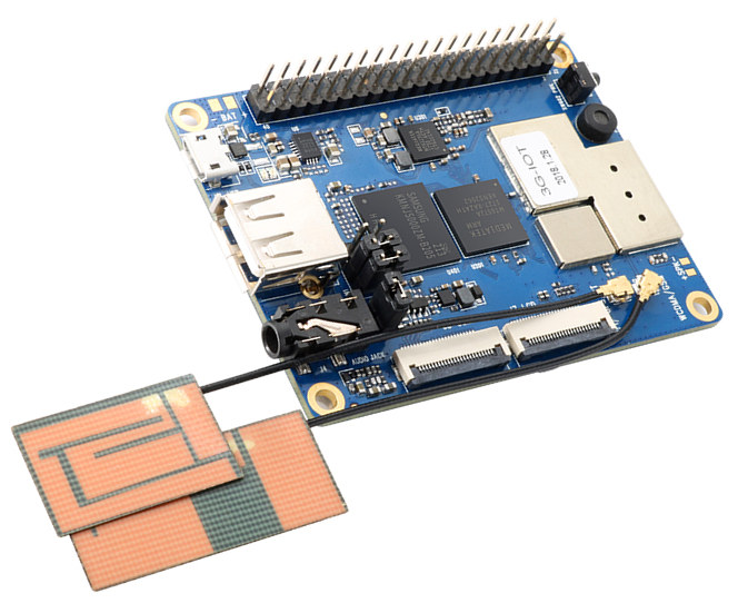
The Shenzhen based company, Xulong who makes the famous Raspberry Pi Clone; Orange Pi has recently launched a new IoT board to expand its IoT family line. The company who launched a 4G board, the Orange Pi 4G board early this year has announced the Orange Pi 3G IoT board, an IoT board that offers worth comparison to the 4G board and comes cheaper.
Orange Pi 3G IoT Board
Just like its other released boards, the Orange Pi 3G is also an open source board. The SBC (Single Board Computer) is powered by a dual Cortex-A7 MediaTek MT6572 running at 1.2GHz speed, a bit lower than the quad-core 1.3GHz MediaTek MT6737 found on the Orange Pi 4G board and higher than the single-core 1GHz RDA Micro 8810PL found on the Orange Pi 2G board.
The Orange 3G boards provide a compromise between using the slower 2G board and the most expensive 4G board. The board will allow users to deploy IoT solution on the widely available 3G networks as compared to 4G networks. The board doesn’t just come with only 3G cellular connectivity but also includes WiFi, Bluetooth, and GPS making it an ideal candidate for use as an IoT gateway.
The board is equipped with a 512MB DDR2 RAM, an onboard 4GB eMMC memory and support for a MicroSD card. It comes equipped with the standard 40-Pin header found on the Raspberry Pi, and this will allow it to have compatibility with some Raspberry Pi Hats.
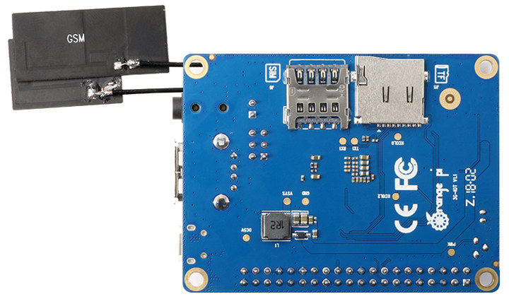
The following are the specifications listed for the Orange Pi 3G-IOT:
WiFi/BT antenna connectors (ext. antennas may be optional)
Display/Media:
LCD interface (FWVGA via FPC ZIF connector) with capacitive touch
MIPI-CSI camera interface
3.5mm earphone audio jack
Mic
Optional speaker
Other I/O:
USB 2.0 host port
Micro-USB port with power support
40-pin expansion header
Other features — 2x LEDs
Power — 5V 2A via micro-USB; power button; optional battery
Dimensions — 68 x 52mm
Operating system — Android 4.4 with C, C++, Kotlin, Java, Shell, and Python support
One major talking point for the Orange Pi 3G-IoT is the OS support. It is still stuck at the ancient Android 4.4 firmware while the Orange Pi 4G already supports Android 8.1. Linux operating system support doesn’t seems to be available for the Orange Pi 3G but we can’t rule it out since the company normally release the Android SDK which also includes an Linux kernel.
The board is available for purchase at the cost of $19.90 and can be purchased online from Aliexpress.