In this episode Shahriar takes a close look at the newly released Siglent SDG6000X Series Pulse / Arbitrary Waveform Generator. SDG6000X is a series of dual-channel Pulse/ Arbitrary Waveform Generators that feature up to 500MHz output frequency, a maximum sample rate of 2.4GSa/s and 16-bit vertical resolution when used as a function generator. The particular reviewed model is the SDG6052X which is the top-end model. The full teardown of the unit reveals the internal architecture of the instrument, DAC / FPGA interconnect as well as the output amplifier structure. Although the limitations of the FPGA prevents the instrument to operate at full 2.5GSa/s in arb-mode, the instrument is capable of providing complex modulation up to the full 500MHz signal bandwidth.
Siglent SDG6000X Series Arbitrary waveform generator review, teardown and experiments – [Link]
Dire situations require unpleasant solutions, an excellent example of this statement is spying and we have seen what the NSA has done in this regard. It goes against proper ethical character, however, it might be needed in certain circumstances. Usually, the first thing a person who wants to spy would do would be to check and closely monitor the internet presence or life of the party being suspected and possibly try to access their profile(s). You could also buy an expensive bug or listening device, plant it somewhere the person goes every day, this could be the person’s house and start eavesdropping.
Another method could be to hire a private investigator or a detective to monitor the person’s actions. However, if they are suspicions, you would probably want to do things discreetly. Going the professional route might work, but is also expensive and somewhat not fun to do (less of learning involved). Do It Yourself (DIY) is the talk of the day, why don’t we go that route? And it’s not like this will be the first time someone is doing that, I once did a project sometime ago that can eavesdrop conversation from a person behind a wall.
TomTechTod released an open source radio transmitter, which measures 5mm by 9mm and is powered by a small battery which has a 4.8mm diameter. This device is actually the smallest radio transmitter I have heard of, and it is super tiny, yet this 433 megahertz (Mhz) transmitter has a high-frequency oscillator and a low-frequency amplifier to ensure maximum efficiency no matter the condition.
Other features include the microphone, the battery holder, two transistors, a resonator too. There is also an antenna with a wire and a resistor. The board is 0.8m thick and can transmit up to 120 meters even with obstacles in the area.
One great advantage that comes with going for a super tiny board such as this one is that the PCBs are not expensive thereby making the board super cheap. The boards are being sold for just 45 cents each.
Files needed to create your own transmitter can be found here, with just a bit of soldering here and there, you have your very own spy bug. A super tiny one to be precise. Of course, I am not encouraging you to start spying on everyone you see I am just saying you should go and have fun.
Computer vision started as a way for computers to understand their surroundings, this requires making a computer with a high-level understanding of digital images or videos. A device that performs computer vision needs to acquire, process, and analyze images to extract data from the real world and turn it into numerical information that can be used for something. The main application for this technology has always been artificial intelligence since giving a computer the ability to understand its surroundings (and learn from them) it’s a huge step towards decision making which is a fundamental part of AI.
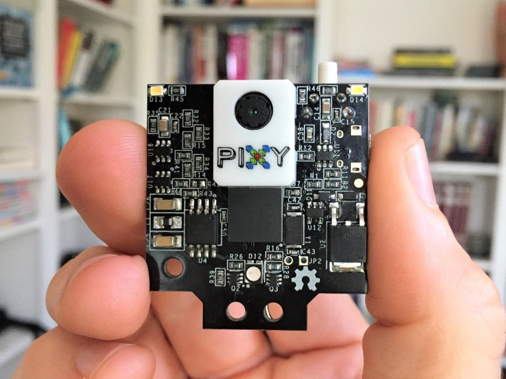
Makers have also started using this type of technology which lead Charmed Labs to create Pixy in 2013. Pixy is a small, easily programmable device used to recognize certain things in its sight. Pixy can be taught objects, and it can also recognize color codes. This year, Pixy 2 was announced, and it can do everything Pixy could plus some additional features.
Pixy 2 has a custom pan tilt mechanism, making it easy to look around. Also, the image processing is now at 60 frames per second. It includes new algorithms for line detection, so it can track lines, and it’s now capable of identifying intersections, and reading signals to make decisions. Signals are simple barcodes which can be printed out and can be easily programmed to a certain instruction to be performed at the sight of that specific barcode.
The device includes a cable to plug it directly into the Arduino, or it can be connected to Raspberry PI via USB cable. It can also communicate via SPI, I2C and UART giving the makers a wide range of options to work with. Finally, the new version has a LED light meant to be used in dark spaces.
A lot of projects for Pixy can be found on the internet, and with the new additions that Pixy 2 offers, there would soon be a lot of applications for this device too. Pixy 2 is smaller, faster, and smarter. As a result, makers will find creative ways to exploit these characteristics in their projects. Finally, Pixy can also be used with Lego Mindstorms (NXT and EV3).
The first Pixy was launched on Kickstarter, but Pixy 2 is not crowdfunding, and its already available to be bought on Amazon or on its official website.
The definitive guide on how to transfer your entire Desktop Work or Entertainment to any Android Smartphone or Tablet
Windows applications are very common for our everyday work and life, so why should we leave them home (or office) on our Windows desktop PCs? What if we could use them on the go, right on our smartphones or tablets? Well, with the modern IT development level this is not the question anymore.
ExaGear Windows Emulator app can solve this issue. This is a virtual machine that allows you to natively run any PC application on any Android mobile device by creating the environment inside the Android operating system and launching the app within this environment. In fact, the overall usability, performance and speed of windows applications stay the same. You literally feel like you are working on your PC.
Run any Windows Software on your Android Mobile Devices – [Link]
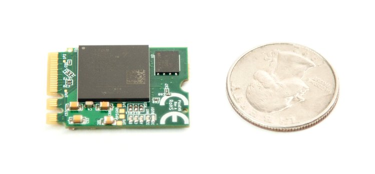
FPGA (Field-programmable gate arrays) devices have gained popularity in the past few years, mainly because of their ability to “become” any digital circuit given that there are enough logic blocks. These devices have endless applications and are sometimes faster which is why they are also used for hardware acceleration. Joining the FPGA industry is the PicoEVB, a small, cheap, open source board designed for PCIe prototyping.
PicoEVB is designed around Xilinx Artix XC7A50T, and measures 22 x 30 x 3.8 mm (about the size of a quarter). Also, it´s schematics will be published making the device open software and hardware. The files will be uploaded on its GitHub repository (there are some sample projects too). It was made to fit in laptop´s M.2 slot, and it can be used as an integrated part of your computer. It does not need any cables since its powered by your computer, and it can be programmed using Xilings Vivado IDE.
Nowadays, PCIe dev boards could cost around $1000, but PicoEVB will cost $219 making it a great competitor in PCIe design. The product can be bought through PicoEVB website, Amazon, Crowd supply and Ebay.
The device has 3 LEDs, 4 digital channels, or 1 analog and 2 digital, or 2 analog channels. Additionally, PicoEVB supports Windows and Linux. The only problem that a user might find is not having an M.2 slot which can be solved with an adapter to mPCIe slot.
Everything needed to program and debug the FPGA is on board, and taking into consideration the low price, it is a great alternative for designing PCIe on a low budget without reducing functionality. It´s the most compact and affordable FPGA development kit currently in the market.
Hi guys, welcome to another Arduino tutorial. Today, I will be showing you how to use the 3.2″color TFT display with Arduino.
The display demand for every project is unique, a project may require just a simple, single color OLED display, while another project may require something bigger, all based on the function the display is to perform. For this reason, as a maker or electronics hobbyist, anyone needs to know how to work with as many displays as possible, that’s why today, we will take a look at how to use the super cheap, 3.2″ color TFT display with Arduino.
Using the 3.2″ HX8357B Color TFT Display with Arduino – [Link]
Arduino is an open source hardware and software company that creates Single Board Controllers (SBC) and Microcontroller kits, and these kits come in a Do-It-Yourself (DIY) form. Arduino can be used by almost anyone because it is inexpensive and also easy for professionals and even amateurs to use. Despite the fact that Arduino kits come in a pre-assembled manner, one can get stuck trying to think of ideas for a project or experiment.
Circuit.io Platform
Situations, where ideas are not forthcoming, are not unusual as it is a brain freeze caused by tension. Arduino has provided open source hardware and software however without ideas to work on; the kits become useless. Most times, there could be a knowledge of what components to use but how to fix them together might be a problem. This is where circuito.io comes in, imagine having a platform that affords one the opportunity to create the coolest projects just by selecting components you want to use.
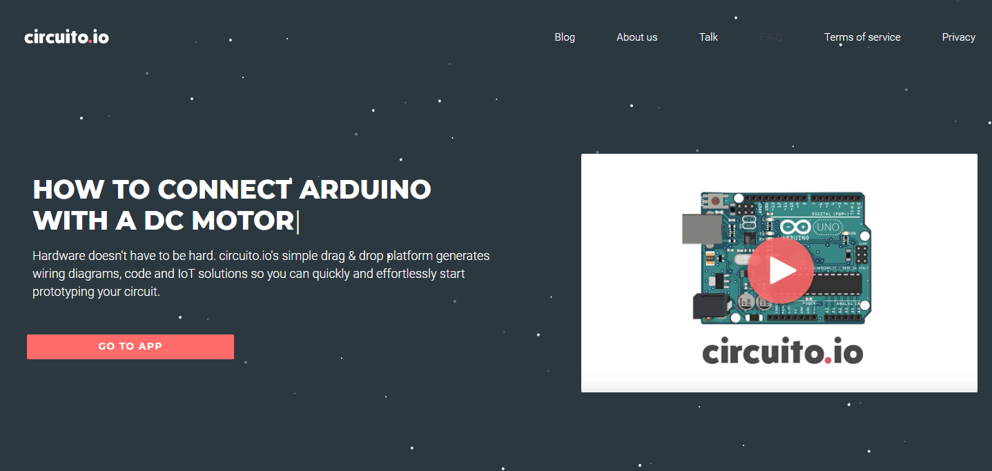
Circuito.io is an online tool for designing complete electronic circuits. The Circuito app generates instant and accurate schematics and code for your electronic circuit. You select the major building blocks, and it computes all the electrical requirements for your selection.
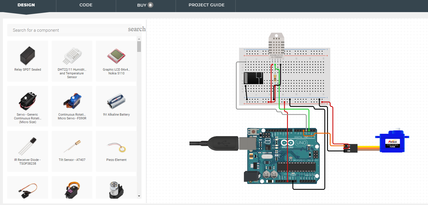
It has a fantastic interface that allows you to drag and drop different parts together. It also has three different sections that one needs to work on before testing, and the first is the Bill of Materials (BoM) called DESIGN.
Here, you check out all the materials available and you then select your preferred options. You choose the components you want, or you think you need and move on to the next section. The next section being the wiring tool which will process, add all necessary additional items required and in return give a well-labeled wiring diagram. Another exciting aspect about circuito.io is that it has an interface that allows you to step through each building component, guiding you through the creation of the circuit; This simply means that you are not working with a static diagram rather one that can move in different directions.
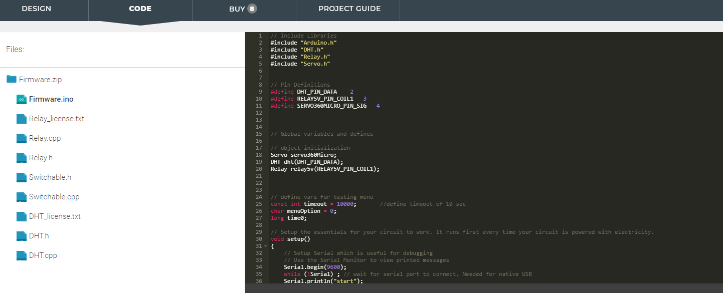
Circuito.io Code Section
It does not end there though, and it only gets better with circuito.io. After building with the aid of the diagram, one can move on to the CODE module; this is a part of the platform that gives examples on how to program every piece used in the previous steps. The platform will solve the problem of hundreds of Arduino users, and it will be a lot easier to program your circuit after going through sample sketches for various pieces. It even acts as a tutorial method for beginners. So if you are stuck on what Arduino project to work on, circuito.io might just be the app for you.
Intel co-founder Gordon Moore predicted in 1965 that the number of transistors per silicon chip would double every two years. This came to be known as Moore´s Law which has been proven accurate for the last fifty years. Many scientists argue that the law is soon to be broken because of physical limitations. The end of Moore´s law would mean a stagnation in computer processing and power and could cause economic issues because changing the whole computer industry to adapt to a new technology would generate really high costs.
Unisantis electronics in association with the Belgian research institute Imec have proposed a solution that not only allows the size to get smaller, but also will have minimum effect in manufacturing process. The Surrounding Gate Transistor (SGT) has a vertical design (as opposed to commonly used transistors which have a horizontal design), this means 50% less occupied area while electron mobility could increase by 300%. Additionally, the vertical structure improves operating voltage, stability, and leakage current.
Nowadays, experts at casino utan spelpaus state that transistors used are about 10 nm, but smaller sizes come with problems such as quantum tunneling which allows the electrons to flow from one gate to the next. SGT´s surround the channel on all sides and that provides better control over the channel. The surrounding gate topology enables a single SRAM cell using just six 5 nm transistors.
Also, Unisantis has developed the process for STG production using the technology available nowadays. As a result, the implementation of this technology in the sector will not mean a huge impact on costs.
Other solutions have been proposed such as software improvements, and parallelization, but these are not long-term solutions since a physical barrier is soon to be reached. Other solutions are too expensive to implement, or the idea is still in early steps. Many industries are working toward solving this problem, but few viable solutions have been reached.
Technology industry demands constant improvement in processing and power efficiency, and Unisantis electronics solutions offers price and performance, this could make this technology the next “standard” for computer products and will allow Moore´s law to stay valid for some more time. Its important to clarify that if Moore´s Law stops being valid, we won´t be the first to feel the impact since latest transistor technology is mainly used in super computers, it will take a couple of years for us to feel the slowing in the improvement rate of everyday devices.
Hi guys, welcome to another Arduino tutorial. Today, I will be showing you how to use the 3.2″color TFT display with Arduino.
The display demand for every project is unique, a project may require just a simple, single character OLED display, while another project may require something bigger, all based on the function the display is to perform. For this reason, as a maker or electronics hobbyist, anyone needs to know how to work with as many displays as possible, that’s why today, we will take a look at how to use the super cheap, 3.2″ color TFT display with Arduino.
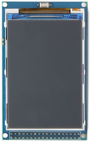
3.2″ Color TFT Display
For this tutorial, we will use the 3.2″ TFT display from banggood. The display which is based on the HX8357B LCD Controller, supports 16-wire DataBus interface and comes with 262K color at 480 x 320 resolution. The module includes an SD card socket, an SPI FLASH circuit and a 5V-3.3V power and Logic Level conversion circuit which makes it easy to use with any microcontroller that uses either 5v or 3.3v logic voltage level. The module can be directly inserted into an Arduino Mega or Due board.
To demonstrate how the display works, we will use the UTFT LCD library for Arduino to display some images and text on the display including an animated graph. All these will show how the display could be used for something like an oscilloscope.
Required Components
The following components are required to build this project:
These components can each be bought via the links attached. The 3.2″ TFT display, as at the time I bought it was listed on the website as a 3″ display but after buying and measuring, the size of the display is 3.2″.
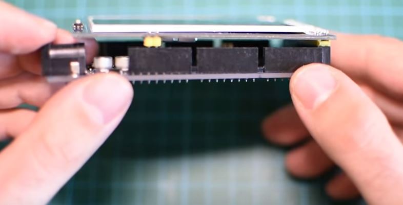
Schematics
The display comes in a shield form, which means it can be plugged directly into the Arduino with which it is going to be used, as such, no schematic is needed. Plug the display into your Arduino Mega or Due as shown in the image below.
Code
To achieve the goals of this tutorial, we will use a simple sample code attached to the UTFT library. The UTFT library is a library created to facilitate easy interaction between a microcontroller and several LCD displays. Unfortunately, the latest versions of the UTFT library has no support for the HX8357B LCD controller which is used to our 3.2″ TFT display. To go round this hurdle, we will be installing a previous version of the library on the Arduino IDE.
The wonderful library written by Henning Karlsen can be downloaded from the link below. The libraries are pre-built for each Arduino board so choose the right one that matches the board you are using from the link below.
Use your favorite library installation method to install the library after downloading and launch an Instance of the Arduino IDE. With the IDE opened, click on file, select examples, select UTFT then select the Display Demo or the UTFT_Demo_480x320 example.
We will attempt to do a brief explanation of the code. The code starts by setting the speed (the wait variable) at which it runs to 2000. This speed can be reduced to zero so the demo can play slowly. After this, we include the utft library and invoke the custom library for the for Arduino Due.
#define WAIT 2000 // Delay between tests, set to 0 to demo speed, 2000 to see what it does!

#define CENTRE 240

#include <TFT_HX8357_Due.h> // Hardware-specific library

TFT_HX8357_Due tft = TFT_HX8357_Due();       // Invoke custom library
Next, we specify the initial color for the fonts to be used. It should be noted that to use custom fonts, they must be pre-loaded into the library by editing the User_Setup.h file in the library.
#define TFT_GREY 0x7BEF
with that done, we proceed to the void setup() function. Under the setup() function, we initialize the LCD using the init command and we ensure the LCD display is on landscape using the set rotation function with a value of 1.
Next is the void loop() function which I personally now use as a reference for functions and how to use them. The void loop function uses quite a number of functions which were used to achieve different effects in the demo. The functions are easy to use and from their name, one can easily tell what they do.
void loop()
{
int buf[478];
int x, x2;
int y, y2;
int r;
runTime = millis();
// Clear the screen and draw the frame
tft.fillScreen(TFT_BLACK);
tft.fillRect(0, 0, 480, 13, TFT_RED);
tft.fillRect(0, 305, 480, 320, TFT_GREY);
tft.setTextColor(TFT_BLACK,TFT_RED);
tft.drawCentreString("* TFT_HX8357_Due *", CENTRE, 3, 1);
tft.setTextColor(TFT_YELLOW,TFT_GREY);
tft.drawCentreString("Adapted by Bodmer", CENTRE, 309,1);
tft.drawRect(0, 14, 479, 305-14, TFT_BLUE);
// Draw crosshairs
tft.drawLine(239, 15, 239, 304, TFT_BLUE);
tft.drawLine(1, 159, 478, 159, TFT_BLUE);
for (int i=9; i<470; i+=10)
tft.drawLine(i, 157, i, 161, TFT_BLUE);
for (int i=19; i<220; i+=10)
tft.drawLine(237, i, 241, i, TFT_BLUE);
// Draw sin-, cos- and tan-lines
tft.setTextColor(TFT_CYAN);
tft.drawString("Sin", 5, 15,2);
for (int i=1; i<478; i++)
{
tft.drawPixel(i,159+(sin(((i*1.13)*3.14)/180)*95),TFT_CYAN);
}
tft.setTextColor(TFT_RED);
tft.drawString("Cos", 5, 30,2);
for (int i=1; i<478; i++)
{
tft.drawPixel(i,159+(cos(((i*1.13)*3.14)/180)*95),TFT_RED);
}
tft.setTextColor(TFT_YELLOW);
tft.drawString("Tan", 5, 45,2);
for (int i=1; i<478; i++)
{
tft.drawPixel(i,159+(tan(((i*1.13)*3.14)/180)),TFT_YELLOW);
}
delay(WAIT);
tft.fillRect(1,15,478-1,304-15,TFT_BLACK);
tft.drawLine(239, 15, 239, 304,TFT_BLUE);
tft.drawLine(1, 159, 478, 159,TFT_BLUE);
// Draw a moving sinewave
int col = 0;
x=1;
for (int i=1; i<(477*15); i++)
{
x++;
if (x==478)
x=1;
if (i>478)
{
if ((x==239)||(buf[x-1]==159))
col = TFT_BLUE;
else
tft.drawPixel(x,buf[x-1],TFT_BLACK);
}
y=159+(sin(((i*0.7)*3.14)/180)*(90-(i / 100)));
tft.drawPixel(x,y, TFT_BLUE);
buf[x-1]=y;
}
delay(WAIT);
tft.fillRect(1,15,478-1,304-15,TFT_BLACK);
// Draw some filled rectangles
for (int i=1; i<6; i++)
{
switch (i)
{
case 1:
col = TFT_MAGENTA;
break;
case 2:
col = TFT_RED;
break;
case 3:
col = TFT_GREEN;
break;
case 4:
col = TFT_BLUE;
break;
case 5:
col = TFT_YELLOW;
break;
}
tft.fillRect(150+(i*20), 70+(i*20), 60, 60,col);
}
delay(WAIT);
tft.fillRect(1,15,478-1,304-15,TFT_BLACK);
// Draw some filled, rounded rectangles
for (int i=1; i<6; i++)
{
switch (i)
{
case 1:
col = TFT_MAGENTA;
break;
case 2:
col = TFT_RED;
break;
case 3:
col = TFT_GREEN;
break;
case 4:
col = TFT_BLUE;
break;
case 5:
col = TFT_YELLOW;
break;
}
tft.fillRoundRect(270-(i*20), 70+(i*20), 60, 60, 3, col);
}
delay(WAIT);
tft.fillRect(1,15,478-1,304-15,TFT_BLACK);
// Draw some filled circles
for (int i=1; i<6; i++)
{
switch (i)
{
case 1:
col = TFT_MAGENTA;
break;
case 2:
col = TFT_RED;
break;
case 3:
col = TFT_GREEN;
break;
case 4:
col = TFT_BLUE;
break;
case 5:
col = TFT_YELLOW;
break;
}
tft.fillCircle(180+(i*20),100+(i*20), 30,col);
}
delay(WAIT);
tft.fillRect(1,15,478-1,304-15,TFT_BLACK);
// Draw some lines in a pattern
for (int i=15; i<304; i+=5)
{
tft.drawLine(1, i, (i*1.6)-10, 303, TFT_RED);
}
for (int i=304; i>15; i-=5)
{
tft.drawLine(477, i, (i*1.6)-11, 15, TFT_RED);
}
for (int i=304; i>15; i-=5)
{
tft.drawLine(1, i, 491-(i*1.6), 15, TFT_CYAN);
}
for (int i=15; i<304; i+=5)
{
tft.drawLine(477, i, 490-(i*1.6), 303, TFT_CYAN);
}
delay(WAIT);
tft.fillRect(1,15,478-1,304-15,TFT_BLACK);
// Draw some random circles
for (int i=0; i<100; i++)
{
x=32+random(416);
y=45+random(226);
r=random(30);
tft.drawCircle(x, y, r,random(0xFFFF));
}
delay(WAIT);
tft.fillRect(1,15,478-1,304-15,TFT_BLACK);
// Draw some random rectangles
for (int i=0; i<100; i++)
{
x=2+random(476);
y=16+random(289);
x2=2+random(476);
y2=16+random(289);
if (x2<x) {
r=x;x=x2;x2=r;
}
if (y2<y) {
r=y;y=y2;y2=r;
}
tft.drawRect(x, y, x2-x, y2-y,random(0xFFFF));
}
delay(WAIT);
tft.fillRect(1,15,478-1,304-15,TFT_BLACK);
// Draw some random rounded rectangles
for (int i=0; i<100; i++)
{
x=2+random(476);
y=16+random(289);
x2=2+random(476);
y2=16+random(289);
if (x2<x) {
r=x;x=x2;x2=r;
}
if (y2<y) {
r=y;y=y2;y2=r;
}
tft.drawRoundRect(x, y, x2-x, y2-y, 3,random(0xFFFF));
}
delay(WAIT);
tft.fillRect(1,15,478-1,304-15,TFT_BLACK);
for (int i=0; i<100; i++)
{
x=2+random(476);
y=16+random(289);
x2=2+random(476);
y2=16+random(289);
col=random(0xFFFF);
tft.drawLine(x, y, x2, y2,col);
}
delay(WAIT);
tft.fillRect(1,15,478-1,304-15,TFT_BLACK);
for (int i=0; i<10000; i++)
{
tft.drawPixel(2+random(476), 16+random(289),random(0xFFFF));
}
delay(WAIT);
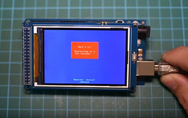
tft.fillRect(0, 0, 480, 320, TFT_BLUE);
tft.fillRoundRect(160, 70, 319-160, 169-70, 3,TFT_RED);
tft.setTextColor(TFT_WHITE,TFT_RED);
tft.drawCentreString("That's it!", CENTRE, 93,2);
tft.drawCentreString("Restarting in a", CENTRE, 119, 2);
tft.drawCentreString("few seconds...", CENTRE, 132, 2);
tft.setTextColor(TFT_GREEN,TFT_BLUE);
tft.drawCentreString("Runtime: (msecs)", CENTRE, 280, 2);
tft.setTextDatum(TC_DATUM);
runTime = millis()-runTime;
tft.drawNumber(runTime, CENTRE, 300,2);
tft.setTextDatum(TL_DATUM);
delay (10000);
}
Take some time to go through the code to better understand what each function does.
Demo
Upload the code to your Arduino board and you should see the display come up after a few minutes, displaying texts, and different other graphics. A view of the display in action is shown in the image below.
You can use either of the two Arduino boards mentioned above for this tutorial. The Arduino due is faster than the Arduino mega so it will run the code faster than the mega. For instance, on the Arduino Due, the code took 23 seconds to get to the end while on the Arduino Mega, it took 44 seconds to get to the end confirming the speed of the Due.
That’s it for this tutorial guys, what cool thing will you be building with this display? feel free to share under the comment section below.
The video tutorial for this project can be watched on youtube here.
Have you ever been to a concert with no way to find the friends you were supposed to meet, seems like things could not get worse but there is no signal and Google map is not working (even when it does, it won’t pinpoint where they are)? Yes, I know a lot of people can relate to this situation. It might not have been at a concert, could have been in a conference, during hiking, cycling events or a beach party. A solution to this problem might be a recent crowdfunded product called Lynq.
Lynq Location Tracker
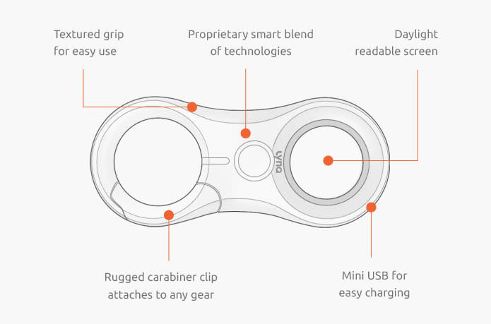
Lynq is a convenient little device that’ll not only help you locate your friends and family in the great outdoors, but it might even save lives. Lynq is an ultimate tracker which gives direction and distance without the aid of connectivity or maps.
Lynq is a 4″x2″x1″ sized tracking device that works with a 3-mile range, it has been tested under various conditions according to the makers and has been declared to have the capability to work anywhere. A capable waterproof and rugged device that can work in the most extreme harsh environment as well.
There are two stages involved when using the Lynq tracking device. The first step is the synchronization stage; with set up of the device you are able to connect to other devices one wants to track. Lynq can connect to a maximum of 15 other Lynq devices. Once you are done with the synchronization stage, everyone is free to roam along as they are within 5 kilometers range. The next thing after splitting up is the linking stage. You link up or should I say Lynq link up with the rest of your group. Just follow the directional indicator displayed on the screen to find them. One can also create or set up a safe zone or meeting point where everyone is supposed to return to.
The device comes in an hourglass shape, and it weighs 73 grams including the weight of the batteries. The battery can last for up to 3 days without charging. The GPS accuracy is 12 to 15 feet, and the accuracy of the directional indicator is 5 degrees. Lynq makes use of proprietary algorithms and communications protocols that combine low power radio, GPS and a custom antenna without the aid of sensors. USB cable for charging, a quick setup card, and a registration card come with the product.
The company is thinking of including an optional connectivity application for people interested in connecting to their mobile phones. The product has a one year warranty for wears and tears or other manufacturing defects. Lynq adheres to the standard privacy policy and does not keep a record of the locations you enter after you successfully get to your destination and there is no way any other person can listen to you or watch you via the device, so it is safe.
Lynq is available for pre-order on the Indiegogo campaign page with a starting price of $89. More information about the Lynq tracking device can be found on the product campaign page.