Arduino, a worldwide leader in microcontrollers and IoT has now added two new members to the family. IoT (internet of things) is a recent term used to describe common devices embedded with electronics, giving them new functionalities such as data gathering, wireless controlling etc. Arduino gave their users the ability to easily navigate through IoT world because of their user-friendly system and has launched different boards and shields throughout the years.
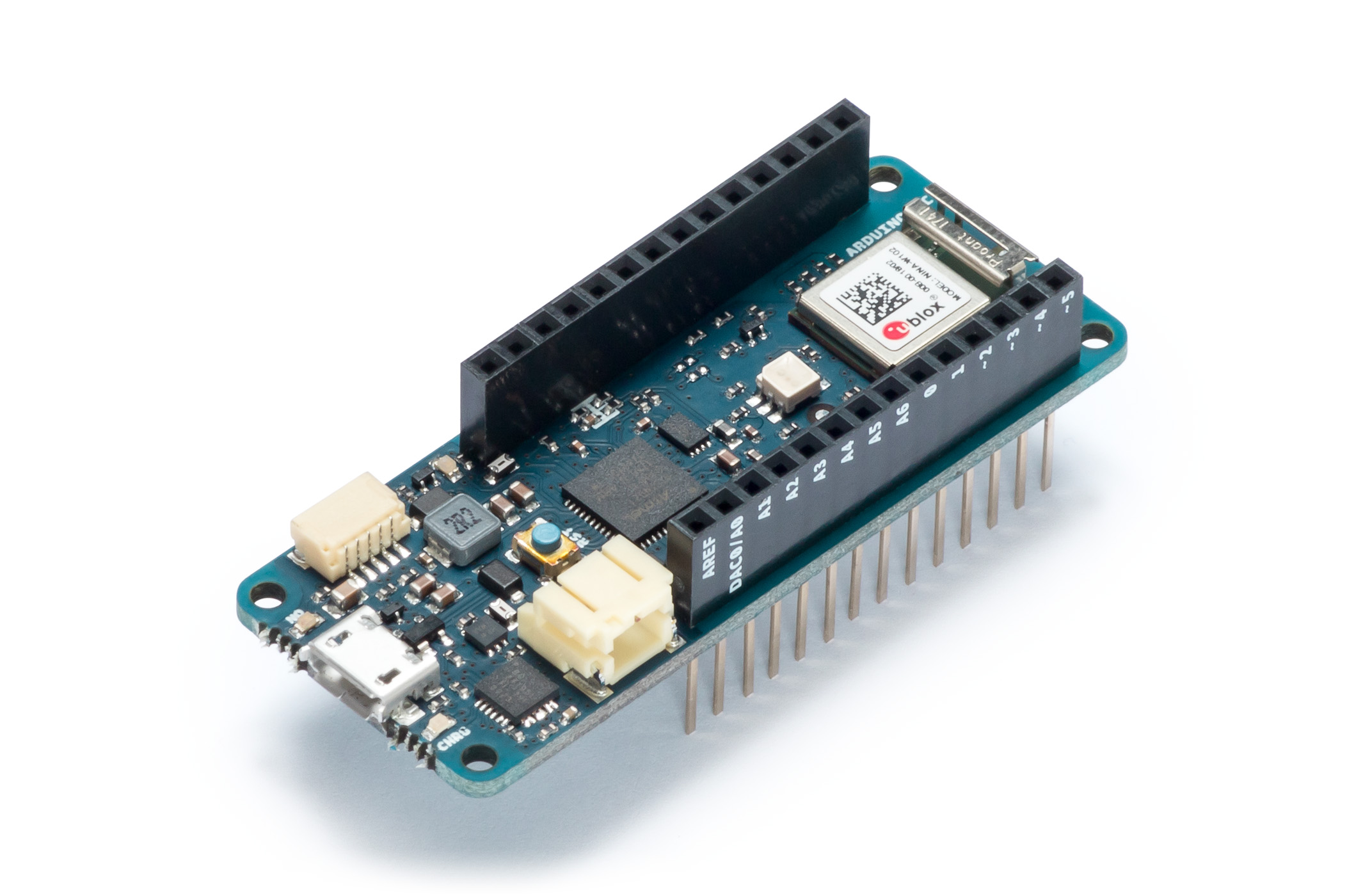
In May, Arduino unveiled the MKR WIFI 1010 and MKR NB 1500, two new wireless connectivity boards designed to compete in the internet of things development.
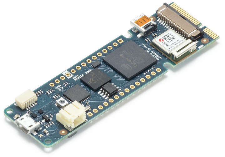
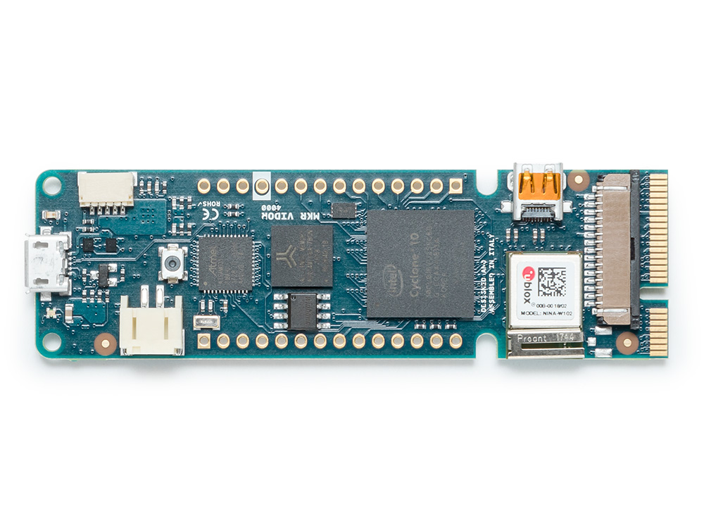
The first one is the descendant of MKR1000, but it now offers low power consumption, and comes equipped with an ESP32- based module manufactured by u-blox. This gives the board 2.4 GHz WIFI and Bluetooth connectivity.
The second one is designed to work over cellular/LTE networks and supports transmissions via AT&T, T – Mobile, Verizon etc. Additionally, it provides faster communication, and power saving because of faster wake up and connection times.
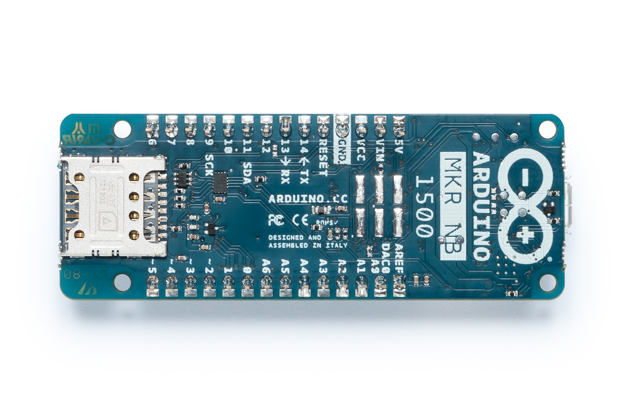
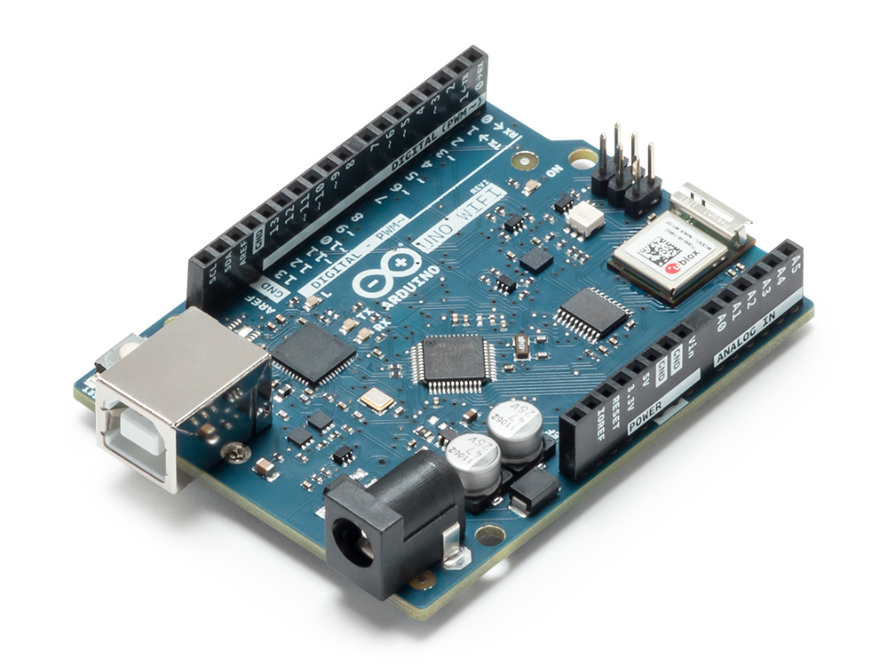
Both boards are compatible with Arduino Uno, MEGA and all MKR boards, and both operate at 3.3 v and have 22 digital I/Os and seven analog inputs. They will be available for sale in the Arduino store in June of this year.
MKR1010 is fully compatible with the Arduino cloud, and has open- source WIFI firmware with allows the user to easily edit, upgrade and fix security flaws. Also, it has two processors, one based on ARM core technology, and the other one based on dual- core Espressif IC. ECC508, a chip for crypto authentication is included for secure communication.
MKR1010 measures only 61.5 mm x 25 mm, and weights only 32 gr making it perfect for IoT projects where size might be a concern, or when the device is meant to go unnoticed. MKR NB 1500 is slightly smaller.
Internet of things has turned into a competition over fastest connections and accurate results. It has been used everywhere from architecture, to medicine and transportation. Massimo Banzi the Arduino co-founder said,
The new boards bring new communication options to satisfy the needs of the most demanding use cases, giving users one of the widest range of options on the market of certified products
Arduino´s new MKR boards will provide users with new capabilities which will lead to more projects with better performance even in the most demanding areas of the market.

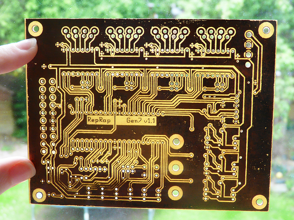
![Making your first Circuit Board – Getting started with PCBway [Part 2]](https://www.electronics-lab.com/wp-content/uploads/2018/05/PCB3-604x270.jpg)


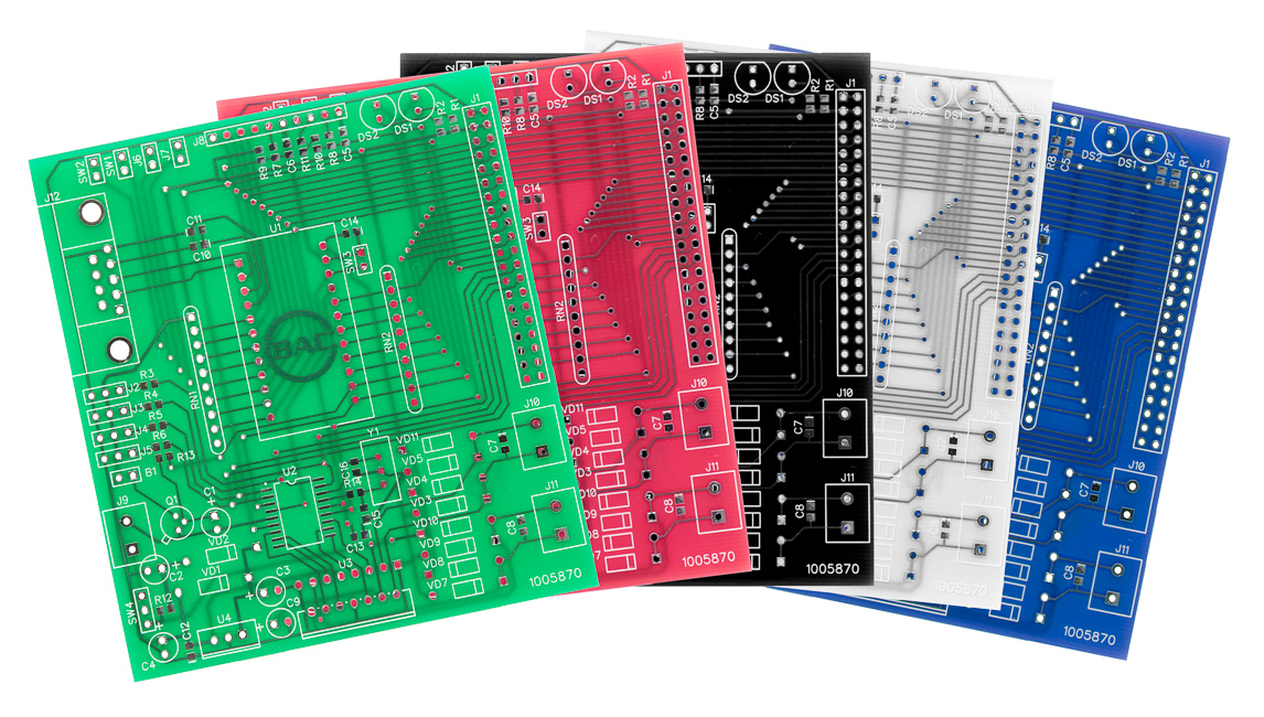
![Making Your First Printed Circuit Board – Getting Started With PCBWAY [PART 1]](https://www.electronics-lab.com/wp-content/uploads/2018/05/pcb-boards-604x270.jpg)