Hi guys, welcome to today’s tutorial. Smart farms are becoming very popular as everyone is beginning to see the benefits in terms of crop health and yield and I know a lot of people that will be interested in smart farm automation. That’s why today, we will be looking at how to use a soil moisture sensor with an Arduino to determine the moisture content in the soil.
Soil moisture is generally the amount of water that is held in spaces between soil particles. It’s is a very important factor that determines the growth of crops and their health.
Instead of the old gravimetric method of measuring soil water content, the soil moisture sensor measures the volumetric water content indirectly by using other properties associated with the soil. The soil moisture sensor used for this tutorial uses electrical resistance of the soil to determine the soil humidity. The electrical resistance of the soil reduces with increase in the amount of water in the soil. The electrical resistance in the soil, however, increases with reduction in the amount of water in the soil. The sensor consists of a probe and a comparator with an adjustable potentiometer which can be used to set the sensitivity of the sensor.
Using a Soil Moisture Sensor with Arduino – [Link]
If your project calls for light sensitivity, it’s hard to beat light dependent resistors (LDRs), also known as photoresistors. They’re available for a few cents each, and their resistance varies based on how much light they receive. In the dark, these devices produce resistances in the megohm range, and can fall to hundreds of ohms or even less when exposed to sufficient light. You first instinct when prototyping this type of device is likely to use an analog input on an Arduino or similar dev board to sense voltage levels. This works quite well in many situations, but you may also want to consider a comparator or operational amplifier (op-amp) to turn this analog input into a simple on/off signal. You could also use one of these components by itself to produce a usable output without the use of a microcontroller.
LDR Analog Input to Microcontroller
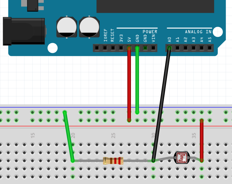
An LDR setup for Arduino Analog Input. Illustration: Jeremy S. Cook in Fritzing
First, let’s examine how a microcontroller would see an LDR input. Using the circuit illustrated in the figure above with an Arduino Uno, an LDR is attached to 5VDC, then routed to the analog input A0. Voltage at the intersection of A0, the resistor, and LDR is divided between the fixed resistor and LDR, which decreases its resistance as light is applied. Voltage at this analog input increases with the lowered resistance in proportion to the amount of light the LDR sees.
The Arduino board is thus able to sense the resulting voltage level and convert it to an analog value. A threshold can be setup to respond to different light levels as on or off, or the analog signal can be used for proportional control. Note that the resistor in this illustration is just a placeholder; it would need to be adjusted based on your LDR sensitivity. You can also use a trimming resistor to tweak output values as needed.
Comparator Digitizes Analog Signal
What if you need light input, but just want an on/off value? Analog inputs can handle this programmatically, but if you’re using an Arduino Uno you’re restricted to the 6 analog pins. There’s also the normally minor issue of additional program complexity. If you need more performance out of your setup, you could turn to a comparator, or operational amplifier (op-amp) set up to act as one, to convert this analog value into a simple on/off signal.
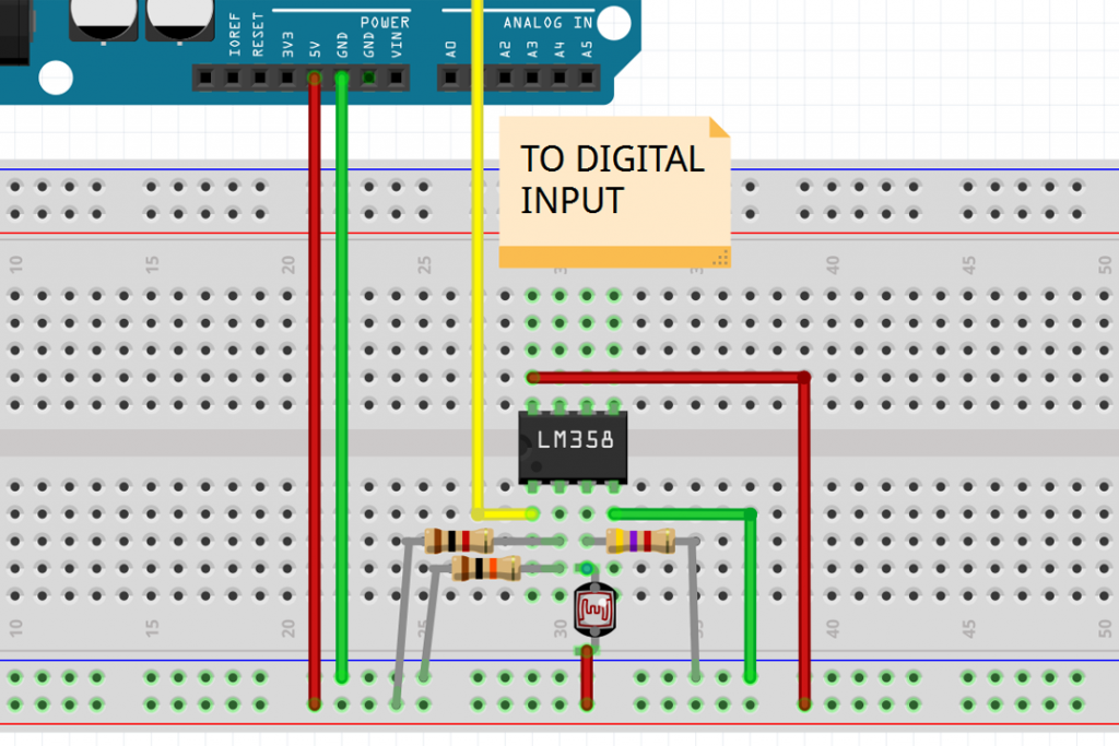
Caption: An LDR and LM358 Op-amp setup to detect light as a binary signal to an Arduino Uno Illustration: Jeremy S. Cook in Fritzing
For example, if you were going to use an LM358 op-amp and LDR to detect light, you could tie the V+ (pin 8) to the 5V supply of your Arduino, ground (pin 4) to the Arduino’s ground, and output A (pin 1) to a digital pin on your Arduino board. The inverting input (pin 2) would be hooked to a voltage divider between +5V and ground, and your LDR would be setup in a voltage divider on the non-inverting input (pin 3). Here the LDR would act as the resistor from +5V to the op-amp input, and the set resistor would run to ground.
This will give you an on/off input to your Arduino without mucking about with any extra programming. Note that because of the way this op-amp operates, the output will be less than 5V, but will be sufficient to trigger the needed input. Obviously this will add some wiring complexity—more work than a few lines of code—so it’s not ideal in all situations.
Comparator Sans Arduino
You’re probably wondering at this point why you wouldn’t simply get a dev board capable of more analog inputs if that’s what is needed. After all, hooking up additional wiring or adding more complication to your PCB isn’t trivial. Certainly there are some applications that call for this, but for really simple electronics, you may not need a microcontroller at all.
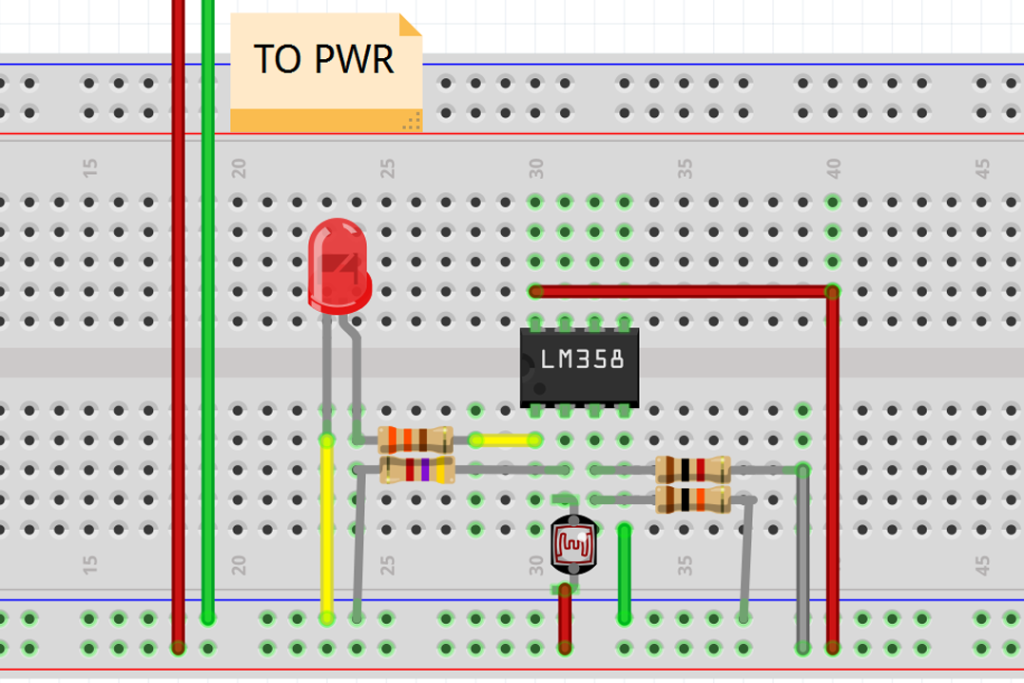
Caption: An LDR and LM358 Op-amp setup to turn an LED on when there isn’t sufficient light available. Illustration: Jeremy S. Cook in Fritzing
One such simple application would be a light that you want to come on when the ambient light drops below a certain threshold. In this application, you’d want to put the resistors only voltage divider on the non-inverting input (pin 3), while the LDR voltage divider would be placed on the inverting input (pin 2). This would cause the voltage on pin 2 to be larger than pin 3 when the light is on, turning the output (pin 1) on when there isn’t enough light.
Of course LDRs are but one type of sensor, and there are many models of op-amps and comparators with different characteristics available depending on your needs. If you’re just starting out with sensors and electronics, using a dev board like an Arduino is a great choice. As you advance in your knowledge, you might also consider analog electronics for your builds. While not appropriate or necessary for every project, it’s a great tool to have available when purely digital processing doesn’t quite fit your application.
Jeremy S. Cook and Zach Wendt are engineers who enjoy sharing how electronic components can best impact applications. Jeremy writes for a variety of technical publications. Zach works for Arrow Electronics, a major supplier of Arduino products.
Whether you are designing an SoC, MCU or other chip, the one common heartache is “freezing RTL.” Up until that point, it’s no problem making a change or update, but once it’s frozen, the chip design is “locked in.” A change after that point could require a new spin that is not only costly, but can also significantly delay the chip development schedule.
Now imagine what it would be like to have no deadline to freeze RTL. What chip designer would not want that? The good news is this is now possible using embedded FPGA (eFPGA). With eFPGA, designers have the flexibility to make changes at any point in the chip development process, even in the customers’ systems. While this is beneficial to any chip design team, it is especially beneficial for applications such as data centers, networking, deep learning, artificial intelligence, aerospace and defense.
What is eFPA?
Many people think that eFPGA is the same as traditional FPGA such as those offered by Xilinx and Altera. This is not the case at all. While the technology is similar, eFPGA requires no SERDES and PHYs because on-chip signaling is very fast. Density is also very similar, although some eFPGA platforms are much better than others so designers need to do their homework and shop around for the best platform. The real difference is the users. FPGA chips are used primarily by systems companies, with some in high volume. eFPGAs are used primarily by chip companies who need to integrate a small amount of FPGA-like flexibility into their chips.
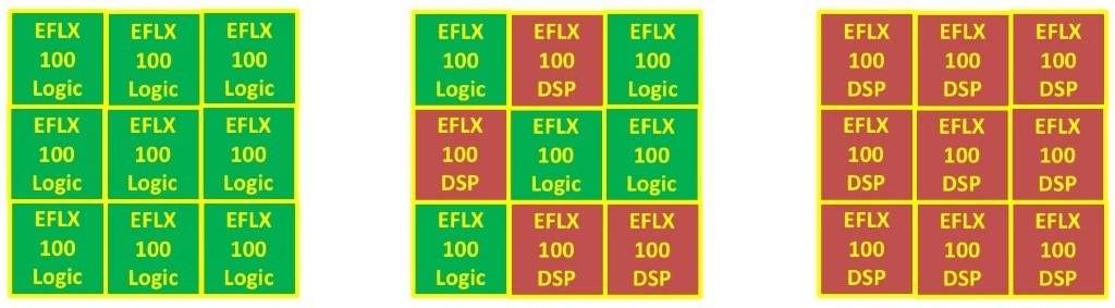
An FPGA combines an array of programmable/reconfigurable logic blocks in a programmable interconnect fabric. In an FPGA chip, the outer rim of the chip consists of a combination of GPIO, SERDES and specialized PHYs such as DDR3/4. In advanced FPGAs, the I/O ring is roughly 1/4 of the chip and the “fabric” is roughly 3/4 of the chip. The “fabric” itself is mostly interconnect in today’s FPGA chips where 20-25% of the fabric area is programmable logic and 75-80% is programmable interconnect.
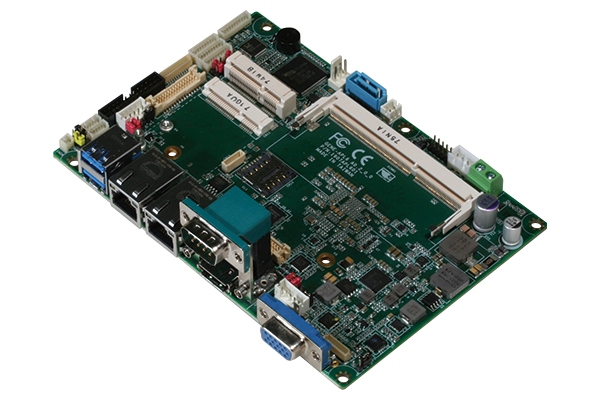
(Taipei, Taiwan – May 3, 2018) – AAEON, one of the world’s leading developers and manufacturers of embedded platforms, launches the GENE-APL6, a rugged subcompact motherboard purpose-built for factory automation and transport applications.
Equipped with an Intel® Pentium® N4200 or Celeron® N3350 processor and DDR3L memory, the fanless GENE-APL6 features a solder-up design, which allows for the easy implementation of a heat spreader to channel heat from the CPU out through the chassis. Additional wide temperature support controls are available on request.
A wide DC input range of 9V to 36V allows the board to overcome fluctuations in power supply and continue running in the unstable environments of factory automation and in-vehicle systems. The GENE-APL6 has been further ruggedized with anti-vibration measures including onboard eMMC storage of up to 128G.
AAEON is a customer-focused company, and it responded to requests for dual LVDS support when designing the GENE-APL6. The low power consumption technology with high noise immunity is ideal for rugged applications, and an HDMI port can be installed as a custom option. Four USB ports, four COM ports, and Mini Card and mSATA expansion slots, give the board the flexibility to match its strength.
“By removing points of weakness, such as storage through expansion slots only, and by adding the features end users want to see, we’ve made the GENE-APL6 the strongest, most complete factory automation and in-vehicle motherboard on the market,” said Julie Huang, AAEON embedded computing division product manager.
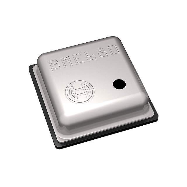
Integrated environmental sensors from Bosch Sensortec, the BME680, for wearables and mobile use, is available from Rutronik UK.
The Bosch Sensortec BME680 expands Rutronik UK’s portfolio to include the first integrated MEMS sensor measuring individually, highly linear, and precise, gas, air pressure, humidity, and temperature. The BME680 is an integrated environmental sensor specifically developed for wearables and mobile applications. It features a space-saving design and low power consumption.
The BME680 detects a number of different gases, including volatile organic compounds in paints containing formaldehyde, varnishes, paint strippers, cleaning agents, furniture, office equipment, adhesives, and alcohol. With accuracy of ±0.12 hPa and a TCO of 1.5Pa/K, the sensor features a precise barometer, says Rutronik UK and high-resolution and low-noise sensors for measuring humidity and temperature, making the BME680 suitable for home automation, indoor navigation, personalised weather stations, or sport and fitness tools.
The BME680 supports the I²C and SPI buses (three- or four-wire), is compatible with a wide range of VDD and VDDIO supply voltages, and can work in standard, forced, and sleep mode. It is supplied calibrated and an air pressure calculation can also be carried out at a later stage using the ACP 2.0 software from Bosch Sensortec.
The sensor is housed in LGA package measuring 3.0 x 3.0 x 0.95mm³. The design supports electromagnetic compatibility (EMC), longevity, and optimal power consumption in various operating modes, adds Rutronik.
To make the set-up process as simple as possible, standard settings for common applications such as weather monitoring, staircase/elevator detection, indoor navigation, and drop detection are already available. The data rate, noise, response time, and power consumption can also be individually adjusted.
The Bosch Sensortec BME680 is available on Rutronik’s e-commerce platform Rutronik24.com (where orders can also be placed directly).Rutronik UK operates as an independent company of the parent company, Rutronik Elektronische Bauelemente GmbH. It has a team of highly-qualified UK employees with broad experience of the electronics industry.
Rutronik Elektronische Bauelemente GmbH is one of the leading broadline distributors for semiconductors, passive and electromechanical components in addition to storage technologies, displays and boards and wireless products. The company primarily targets automotive, medical, industrial, home appliance, energy and lighting markets.
Hi guys, welcome to today’s tutorial. Smart farms are becoming very popular as everyone is beginning to see the benefits in terms of crop health and yield and I know a lot of people that will be interested in smart farm automation. That’s why today, we will be looking at how to use a soil moisture sensor with an Arduino to determine the moisture content in the soil.
Soil moisture is generally the amount of water that is held in spaces between soil particles. It’s is a very important factor that determines the growth of crops and their health.
Instead of the old gravimetric method of measuring soil water content, the soil moisture sensor measures the volumetric water content indirectly by using other properties associated with the soil. The soil moisture sensor used for this tutorial uses electrical resistance of the soil to determine the soil humidity. The electrical resistance of the soil reduces with increase in the amount of water in the soil. The electrical resistance in the soil, however, increases with reduction in the amount of water in the soil. The sensor consists of a probe and a comparator with an adjustable potentiometer which can be used to set the sensitivity of the sensor.
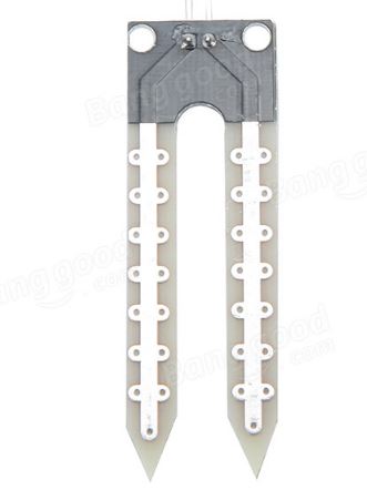
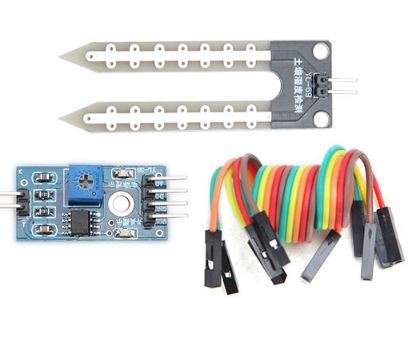
Soil Moisture Sensor
Due to the desire and design techniques of different manufacturers, the sensor comes in different forms, cheap version of the sensor comes with a separate comparator board which is connected to the probe via jumper wires as shown in the image above, this version of the sensor always include an Analog to digital converter which allows the use of the sensor as a digital sensor. Other versions of the sensor from manufacturers like Sparkfun may have all the electronics attached to the probe. Irrespective of the sensor’s form factor, the connections, and use is the same.
Some of the features of this sensor include:
Operating voltage: 3.3V~5V.
Adjustable sensitivity (shown in blue digital potentiometer adjustment)
Dual output mode, analog output more accurate.
A fixed bolt hole for easy installation.
With power indicator (red) and digital switching output indicator (green).
Having LM393 comparator chip, stable.
Panel PCB Dimension: 3cm x 1.5cm.
Soil Probe Dimension: 6cm x 2cm.
Cable Length: 21cm.
The probe of the sensor shown below consists of two large exposed pads that are used to test the electrical conductivity of the soil.
Our goal for this tutorial is to demonstrate how to use this interesting sensor by measuring the soil humidity and displaying the value either on the Arduino Serial monitor or on the Nokia 5110 LCD.
Required Components
The following components are required to build this project;
These components can all be bought via the link attached to each of them.
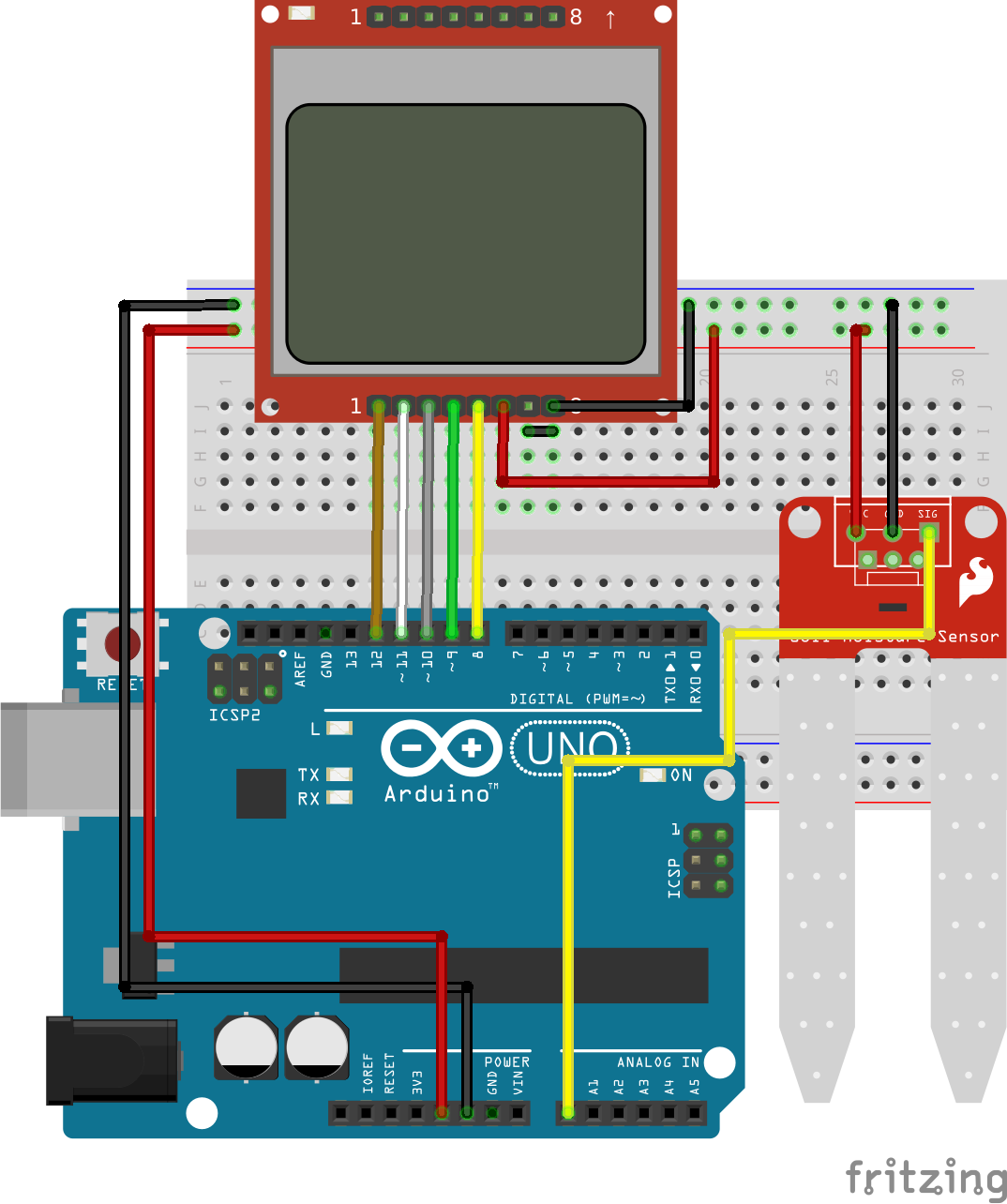
Schematics
Connect the components as shown in the image below.
The pin connection between the Arduino and the soil moisture sensor is described below to make the schematics easier to follow.
Moisture Sensor – Arduino
VCC - 5V
GND - GND
SIG - A0
We have covered how to use the Nokia 5110 LCD display in several tutorials on this website so I won’t be going into the details of how to use the display. For those who may find it difficult to follow the schematics, the pin connections for the LCD is also described below.
Go over the connection once more to ensure everything is connected as it should be.
Code
Two Arduino sketches are provided for this tutorial. The first one is for those who are comfortable with displaying the data on the serial monitor while the second sketch contains the code necessary to display the soil humidity percentage on the Nokia 5110 LCD display. Since we have covered the use of Nokia 5110 LCD display in several tutorials on this website, I will only explain the first sketch which contains the code to obtain the soil moisture level and display on the serial monitor.
The concept behind the code for this tutorial is simple, since we know the range of the Arduino ADC is between 0 and 1023, we are sure whatever readings the sensor provides will be within that range, thus, when we read the analog value provided by the soil moisture sensor, we use the Arduino map function to convert whatever value was read to a value between 0 and 100, indicating a percentage. The percentage is then displayed on the serial monitor or on the LCD Display. A percentage is used for good UX as it is easier for the user to understand.
To briefly explain the code, the first thing we do is to declare the analog pin of the Arduino to which the moisture sensor is connected after which we declare other variables that will be used later on in our code.
   //////////////////////////////////////////////
  //        ARDUINO SOIL MOISTURE DEMO        //
 //                                          //
//           http://www.educ8s.tv           //
/////////////////////////////////////////////


int sensorPin = A0;
int sensorValue = 0;
int percent = 0;
Next, we move to the void setup() function where we initialize the serial communication so we can display data on serial monitor.
void setup() {
  Serial.begin(9600);
}
Next is the void loop() function. We start the function by reading the value from the sensor then we call the convert to percentage function after which we display the converted value on the serial monitor.
The code for the conversion to percent function is shown below. As mentioned earlier, it takes in the analog value and converts it to the percentage value using the Arduino map function.
int convertToPercent(int value)
{
  int percentValue = 0;
  percentValue = map(value, 1023, 465, 0, 100);
  return percentValue;
}
The procedure described above is the same for the second sketch, we only need to include dependencies required for the Nokia 5110 LCD Display.
The complete code for the project is attached under the download section of this tutorial.
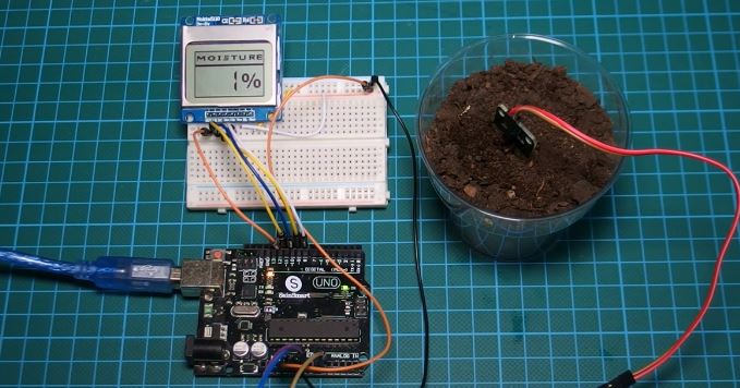
Demo
Upload the code to your Arduino and setup the system with the soil sensor dipped in a fairly dry soil you should see the LCD/serial monitor display the amount of water in the soil as shown in the image below.
Demo – Dry soil
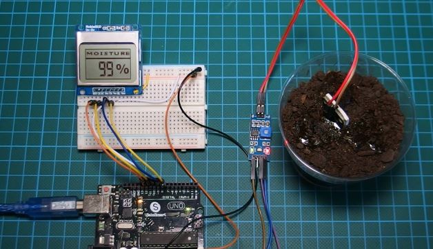
By adding a little amount of water to the soil, the resistance in the soil is lowered and you can see the change immediately on the Display/serial monitor as shown in the image below.
Demo – Wet Soil
This project is a big step towards smart irrigation system as the change in the soil level can be set to activate a relay to turn on a pump to water plants once the water level is low.
That’s it for this tutorial guys, don’t forget to leave questions, and comments, in the comments section of the tutorial.
Till next time, Keep Building!
The youtube video for this tutorial is available via the attached link
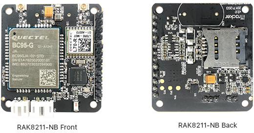
In the last few years, we have seen a lot of love poured towards the hardware ecosystem especially hardware related to the Internet of Things applications (hardly would you find any board that doesn’t have one or two IoT offerings). Some boards give basic IoT functionality like providing you with a basic IoT connectivity interface with no extra add-ons while some boards goes the extra mile by providing more, RAK8211-NB iTracker is one of those boards.
RAK8211-NB iTracker
Rak Wireless, the Chinese based hardware company has recently launched a new IoT focused board called the RAK8211-NB iTracker based on the Quectel BC95-G NB-IoT Module, Nordic Semi nRF52832 Bluetooth 5 chip, and Quectel L70-R GNSS module. The Quectel BC95-G is a high-performance NB-IoT module which supports multiple frequency bands of B1/B3/B8/B5/B20/B28* with extremely low power consumption. The ultra-compact 23.6mm × 19.9mm × 2.2mm profile makes it a perfect choice for size-sensitive applications like the RAK8211-NB iTracker. The Quectel provides a flexible and scalable platform for migrating from GSM/GPRS to NB-IoT networks.
The RAK8211-NB is a module geared towards asset tracking and management due to its arrays of features, and it’s one of those board that supports the new Bluetooth 5.0. The board includes a vast array of connectivity options (NB-IoT, BLE 5.0 and GPS). The asset tracker module comes with five different sensors to monitor motion and environmental data, and can optionally be powered directly by a solar panel. It comes with accompanying sensors like an accelerometer, a light sensor and a barometric sensor. At the heart of the RAK8211-NB is the Nordic NRF52832 SoC. The nRF52832 SoC is built around a 32-bit ARM® Cortex™-M4F CPU with 512kB + 64kB RAM. The embedded 2.4GHz transceiver supports Bluetooth Low Energy, ANT, and proprietary 2.4 GHz protocol stack.
The RAK8211-NB module is Arduino friendly and can be programmed using the IDE. The board also provides SWD interface for programming the NRF52832 core. The combination of BLE and NB-IoT offers flexible low power consumption development along with a myriad of application option ranging from telemetry to live tracking and environment sensing. The RAK8211-NB iTracker provides applications in the following areas:
Vehicle location/fleet transportation management.
Safety monitoring of old/young children.
Animal protection and animal husbandry management.
Asset tracking and management.
Prototyping for NB-IoT Applications.
The below are some of the specifications of the module:
Connectivity
NB-IoT via Quectel BC95-G (Global) wireless communication module + SIM card socket
Bluetooth 5 via Nordic Semi nRF52832 Arm Cortex-M4F micro-controller (Arduino compatible)
LIS2MDL ultra-low-power, high-performance 3-axis digital magnetic sensor.
Tilt sensor
BME280 pressure, humidity and temperature sensor
The OPT3001 intensity of light sensor
Expansion – 3x headers with SWD, 2x sensor out + tilt out (also usable as GPIO and analog inputs), 3.3V, GND, and reset
Power Supply – 3.5V to 18V via solar panel (P2) or battery (P3)
Dimensions – 43mm x 38mm x 18mm
Temperature Range – 40°C to +85°CBLE Features
The company provides instructions to use the module with the Arduino IDE, Espruino (JavaScript) and Arm Keil tools. The RAK8211-NB iTracker kit is available and sells for $98.40 + shipping on Aliexpress. Rak Wireless also offers another variant of RAK8211 with RAK8211-G based on the most of the same features, except GPRS is used instead of NB-IoT. It is sold for $87.40 + shipping.
Back in March 2016, Espressif Announced the ESP8285 Wi-Fi Chip, a supposed killer of the favorite ESP8266 chip. The new chip is an ESP8266, but with the flash memory onboard – 1MB flash memory. Espressif’s ESP8285 delivers highly integrated Wi-Fi SoC solution to meet users’ constant demands for efficient power usage, compact design and reliable performance in the Internet of Things industry. With the complete and self-contained Wi-Fi networking capabilities, ESP8285 can perform either as a standalone application or as the slave to a host MCU. When ESP8285 hosts the application, it promptly boots up from the flash. The Chip is also ultra-small as compared to the ESP8266 making it suitable for applications like in wearables.
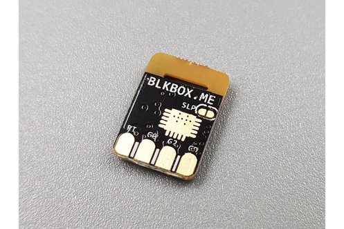
Taiwan based Blkbox may have designed the world’s smallest WiFi IoT module with their Espressif Systems ESP8285 based BB-E01P module which is pin-compatible with the ESP-01 module, and measuring just 10×14 mm. Several ESP8285 modules have been released, but the Blkbox version is probably the smallest ever. Itead Studio’s PSF-A85, an ESP8285 Wireless Module measures just 14mm*135mm, and even the Electrodragon ESP8285 WiFi module measures 15.5mm x 17.8mm. With this, the Blkbox module might be the smallest we currently have. The BB-E01P is the equivalent of the Blkbox predecessor BB-E01 with reduced dimensions.
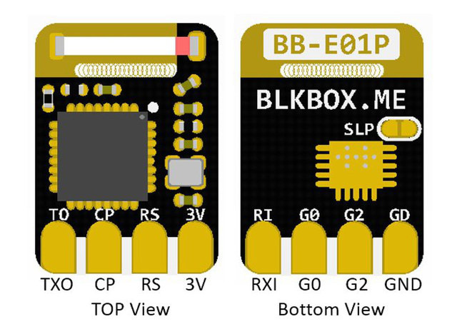
BB-E01P ESP8285 Pinout
The following are the specification of the Blkbox BB-E01P ESP8285 WiFi module:
Connectivity – 802.11 b/g/n WiFi with chip antenna
Expansion – 8-pin (2.54mm pitch) with Tx/Rx, CP, RS, GPIO0, GPIO2, 3V, GND (Same layout as ESP-01)
Interface – UART
Misc – Jumper supports Deep Sleep Mode (AT+GSLP)
Firmware Version: AT v1.6 / SDK v2.2
Power Supply – 3V -3.6V
Dimensions – 10 x 14 mm
Pin Pitch – 2.54mm
The Blkbox board is preloaded with the firmware version AT v1.5/SDK v2.2. Just like every other Blkbox boards, the module can be purchased on Tindie for $6.80 + shipping.
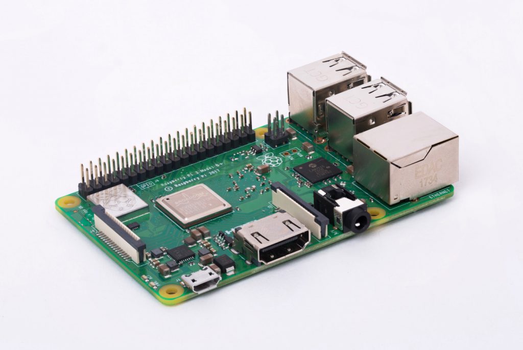
The third revision of the Raspberry Pi can best be summed up by the old adage of more of the same. A faster processor and Power over Ethernet capability were advertised – OEMsecrets tells you what you need to know.
Raspberry Pi’s are always sold via the ecosystem. This is a promise which the foundation, by and large, manages to keep: if you use a sufficiently recent version of RaspBian so that the new SOC is supported, the same memory card can also be used in older versions of the process computer. When looking at the thing from the top, not many differences can be seen. The most important change is the addition of the four pin header for the Power over Ethernet hat: it might cause problems with some cases. Other than that, the physical dimensions remain the same.
The third revision of the Raspberry Pi can best be summed up by the old adage of more of the same – [Link]
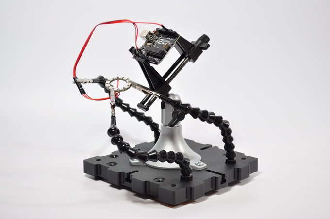
The most capable and expandable third hand system for holding your projects is getting a major upgrade! Jotham McMillan writes:
Dear fellow Kickstarter Patrons, at various points in my life, I’ve built RC cars, messed with Arduino projects, built custom computers, assembled models, added LEDs to my snowboard and so on. A common thread in these projects was the need to hold pieces in place while I soldered, glued or painted my parts.
The usual solution is some type of third hand tool…and there are some good ones out there but none of them have the functionality that I was looking for and they often had compromises with the parts they use. My wife can tell you that I don’t like to compromise thus…
RaptorLoc Pro – A versatile modular third hand system – [Link]