Hardkernel has produced a single-unit version of its four-unit, 32-core Odroid-MC1 cluster computer for running Docker Swarm, Build Farm, and other parallel computing applications. The design offers greater flexibility for users to combine Odroid-MC1 Solo units for a “single unit, 2, 3, 4, 5, 6, or n stackable cluster”. The octa-core Odroid-MC1 Solo costs $48. Combing one or more Solo units with the original 4-unit MC1 acts as a single cluster.
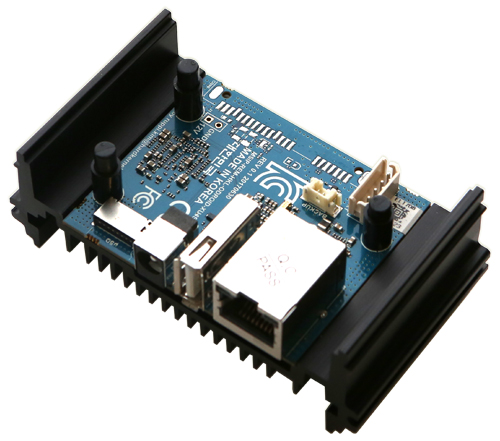
Odroid-MC1 Solo
The Odroid-MC1 Solo and Odroid-MC1 use an Odroid-XU4S SBC that is similar to the SBC that powers the Odroid-HC2 network attached storage (NAS) device. Both boards are smaller, stripped-down, headless version of the open-spec Odroid-XU4 SBC.
Like the Odroid-HC2 board, the MC1 board has removed the XU4’s HDMI port, 2x USB 3.0 ports, optional eMMC, and 30- and 12-pin GPIO connectors. Like the Odroid-XU4, the boards are powered by the Samsung Exynos5422 SoC with four Cortex-A15, four Cortex-A7 cores, and Mali-T628 GPU.
All these boards are equipped with 2GB LPDDR3 (in a PoP configuration), as well as a GbE port, USB 2.0 host port, and a bootable microSD slot with UHS-1 support. The XU4s used on the Odroid-MC1 lacks the one additional feature found on the HC2 NAS computer that is a USB 3.0-based SATA port.
The new Odroid-MC1 Solo board, including the stacking case, measures 92 x 42 x 29mm. These boards are powered by a 5V/4A power supply. A UART, an RTC with battery connector, as well as “M3 x 8mm” self-tapping screws are also there on this board. The XU4-compatible Linux image is based on Kernel 4.14 LTS.
Key Specs:
CPU Samsung Exynos5422 ARM® Cortex™-A15 Quad 2.0GHz/Cortex™-A7 Quad 1.4GHz
DRAM Memory 2Gbyte LPDDR3 RAM PoP (750Mhz, 12GB/s memory bandwidth, 2x32bit bus)
GPU Mali™-T628 MP6 OpenGL ES 3.1 / 3.0 / 2.0 / 1.1 and OpenCL 1.2 Full profile
Micro-SD Slot UHS-1 compatible micro-SD slot up to 128GB/SDXC
USB2.0 Host HighSpeed USB standard A type connector x 1 port
LEDs Power, System-status
Gbit Ethernet LAN 10/100/1000Mbps Ethernet with RJ-45 Jack ( Auto-MDIX support)
Power Input DC Barrel Jack Socket 5.5/21.mm for 4.8V~5.2V input
Size 92 x 42 x 29 mm
The Odroid-MC1 Solo is available now for $48. More information may be found at Hardkernel’s Odroid-MC1 Solo shopping page.
Regardless of how strong a password is, or what level of code-based authentication a website is using, any system that sends codes in a text message can be hacked by a skilled hacker. The most secure way to set up two-factor authentication is to use a reliable app on a smartphone to generate those six-digit codes or to carry a piece of hardware that can verify user’s true identity.
Yubikey can simplify and secure your online login
A device like the YubiKey is just that sort of security enhancing hardware. These little key-shaped fobs plug into user’s computer and along with the password, complete the second half of a 2FA web login. A hacker might find a way to lay his hands on one’s passwords or intercept a six-digit 2FA code while it’s being sent to the phone, but they’ll have a hard time to snatch an actual key off user’s keychain. A YubiKey will directly provide another and more convenient method of authentication.
The YubiKey is like other, similar devices having a small metal and plastic key about the size of a USB stick. They plug into a computer, and some also can connect to the phone. It can be used in either place, along with the password to authenticate web logins. It can be thought of as a physical key that, instead of unlocking a door, unlocks user’s online life.
There are several manufacturers that make these types of keys, and they all basically work the same way. They fulfill an industry standard called Universal 2nd Factor, or U2F. The standard combines hardware-based authentication with public key cryptography. This method of cryptography is extremely difficult to compromise. These U2F keys simplify the process of securely accessing online services like Google, Facebook, Dropbox, Windows, and Mac OS.
The YubiKey is made by the company Yubico and meets the U2F and FIDO2 standards. The keys are durable, water-resistant, and battery-free. The full-size YubiKey 4 Series ranges from $40 to $60 and comes in versions for USB-A ports or USB-C ports. For Android users, there’s the NFC-compatible YubiKey Neo for $50.
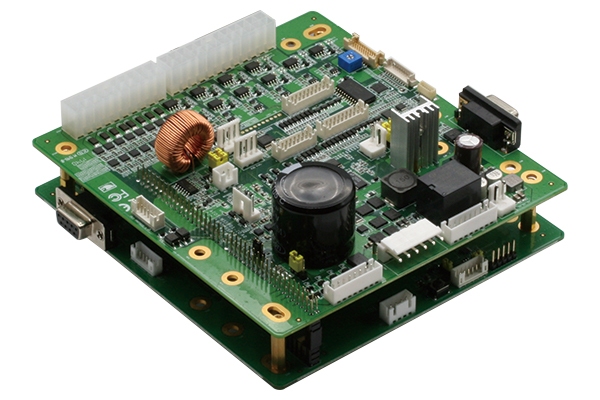
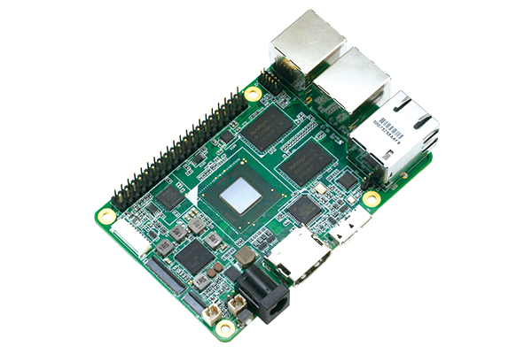
(Taipei, Taiwan – April 24, 2018) – AAEON, a leading developer of industrial computers and intelligent retail systems, releases an updated version of its Intelligent Vending Development Kit. The kit is a complete hardware solution that makes it easier than ever before for retailers to implement the latest smart vending technologies.
The kit includes a vending machine controller unit, a separate UP Board PC unit to handle the interactive retail functions, a motor for the machine’s internal mechanisms, a camera, a QR Code device, and all the cables needed to connect these components. Additional WiFi and Bluetooth connectivity components are also available on request.
AAEON is now offering two versions of its Intelligent Vending Development Kit, but both come with the Windows 10 IoT Enterprise OS and a customer-friendly API pre-installed. The kits also utilize the power of the UP Board and its Intel® Atom™ x5-z8350 processor and DDR3L memory to manage a fast, effective facial recognition program.
As a customer approaches the vending machine, an image of their face is captured and their age range, gender and mood are detected. Based on the results, a particular set of products are recommended. Crucially, the process happens almost instantaneously, so there’s no risk of the customer being inconvenienced.
The latest version of the development kit also incorporates Microsoft Azure and Power BI services. With this service, information about every product sold and the gender, age range and mood of each buyer is collated by Azure and broken down by Power BI’s data analytics tools. The result is real-time inventory control information and a series of insightful customer behavior reports and charts that operators can access at any time. Users who buy this version of the development kit will also receive a 60-day free trial for the Power BI Pro service.
“Intelligent vending machines represent the future of automatic retailing,” AAEON design manufacturing product manager Brenda Huang said. “Increasingly, customers are both expecting and relying on intelligent, interactive systems, and the data these machines collect will also give businesses an edge over their competitors.”
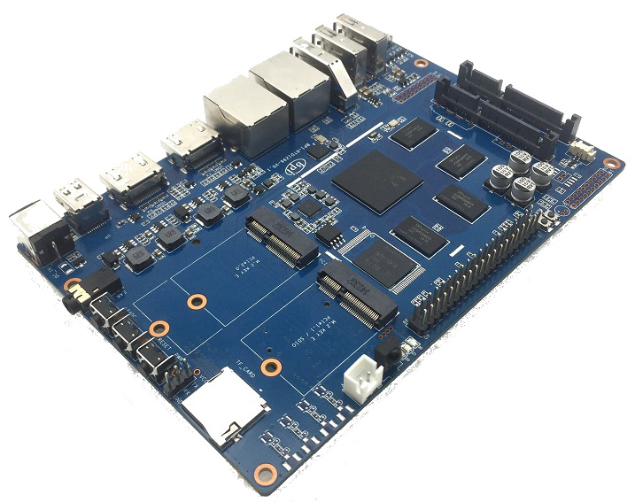
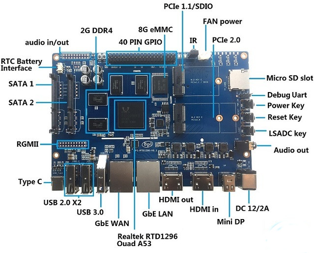
SinoVoIP, the makers of the DIY Raspberry Pi lookalike board, the BananaPi has unveiled a new maker board designed for media, storage, and networking applications called the Banana Pi BPI-W2. The Banana Pi BPI-W2 is based on the Realtek RTD1296 processor. Recently, Realtek worked on the first RTD1296 processor with extra Gigabit Ethernet, SATA interfaces and USB 3.0. The Realtek RTD1296 is a high-end processor which already powers some Android TV Boxes like the Zidoo X9S and some others but there is little adoption in the general maker’s ecosystem. SinoVoIP is hoping to bring the powerful Realtek processor to the maker’s world with the introduction of the BananaPi BPI-W2 which is a friendly maker’s board.
BananaPI BPI-W2
BananaPi BPI-W2 is going to be SinoVoIP’s fourth board so far and comes with some improved features and modifications. The board integrates a Realtek RTD1296 SoC with 4x Cortex-A53 cores clocked at up to 1.5GHz with a high-end Mali-T820 MP3 GPU. It also incorporates dual GbE ports and a GbE WAN Port for router applications. It includes a variety of peripherals, including an HDMI input in addition to the HDMI output, and a mini-DisplayPort. A single PCIe2.0, PCIe1.1 & SDIO, M.2 interface, USB 2.0, USB 3.0 Port, SATA port, the WAN port provides support for 802.11ac/n WLAN connection through PCI-e port. From this onboard features, it is obvious the board is designed for media, storage, and networking applications.
Just like other Banana Pi boards in the past, the BananaPi BPI-W2 provides support for popular Raspberry Pi add-on boards through a 40-pin header. Some of its other features include an RTC, IR, debug, audio I/O, and a 12V input.
BananaPi BPI – W2 is expected to work with Android 6.0 and 7.0 as well as multiple OS such as Open WRT, Debian, Linux, Ubuntu Linux and many more. The router can be used for home entertainment, high wireless performance, automation of a building and so on.
Below are some of the specifications of the BananaPi BPI-W2 board:
SoC – Realtek RTD1296 quad-core Cortex A53 processor with ARM Mali-T820 MP3 GPU
System Memory – 2GB DDR4 RAM
Storage – 8GB eMMC flash (optional 16, 32 or 64GB), 2x SATA 3.0 interfaces, micro SD slot up to 256GB
Video
Output – HDMI 2.0a up to 4K @ 60 Hz, mini DP
Input – HDMI 2.0 input up to 1080p60
Playback – HDR, 10-bit HEVC/H.265 up to 4K @ 60fps, H.264 up to 4K @ 24 fps, VP9 up to 4K @ 30 fps, BDISO/MKV, etc…
Audio I/O – HDMI, mini DP, 3.5mm audio jack
Connectivity
2x Gigabit Ethernet
SIM card slot (requires mPCIe modem)
USB – 1x USB 3.0, 2x USB 2.0 ports, USB type C interface (still no idea if video and power are supported)
Expansions
1x M.2 Key E “PCIe 1.1/SDIO” slot
1x M.2 Key E “PCIe 2.0” slot
40-pin “Raspberry Pi” GPIO header
Debugging – 3-pin UART connector
Misc – Power, reset and LSADC keys; RTC battery connector; IR receiver; fan header
Power Supply – 12V /2A via power barrel connector
Dimensions – 148 x 100.5 mm (same as Banana Pi R2 board)
Banana Pi BPI-W2 SBC is billed as open source, and should eventually ship with schematics and other documentation. The board is available and can be purchased for $93 on Aliexpress. More information about the board can be found here.
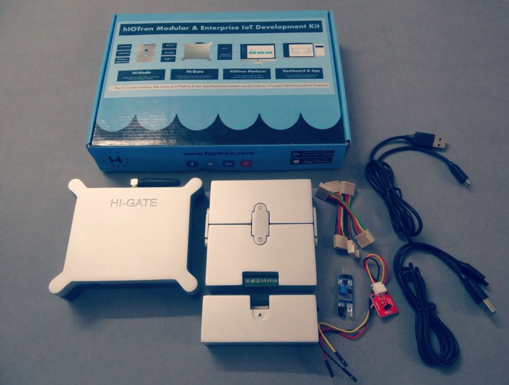
HioTron IoT Kit is a modular and enterprise IoT kit that is entirely pre-programmed prototyping kit for quickly building and testing IoT concepts. All modules are plug-n-play, allowing for flexible prototyping, customization & production. This set of kit is made by the Indian based company HioTron, which specializes in IoT solutions development. This Kit includes Hardware, IoT Platform & User App/Dashboard needed to build quickly any IoT application right from Scratch to Production.
Hiotron Development Kit
One of the challenges that come with embarking on IoT project is that of the platform, software, wireless standard, API, and hardware selection. We have numerous IoT enabled hardware in the market, with each having their own software stack and also several IoT platforms available to pick from. The process of going through these selection pools, valuable and productivity time could be lost and still not arrive at something that genuinely works or is efficient. Hiotron’s goal is to solve this by providing a complete package that can be used from PoC (Proof Of Concept) to Production. HioTron complete IoT solution which includes not only the hardware building blocks (Nodes & Gateway) needed to quickly prototype a wireless IoT system from scratch but most importantly hIOTron enterprise IoT™ Platform is integrated with custom mobile application & GUI dashboard that enable user to get up and run PoC of any idea as easily and quickly as possible.
The IoT Kit is ideal for makers, enthuthat siast, startups and even organization that wants to embark on IoT projects in the areas of smart cities, agriculture, industrial & smart factories, energy, healthcare, logistics, and several others. The kit is modular which means you can easily stack in add-ons on top of existing ones or add another device to the network infrastructure. The kit includes the following:
Hi-Node
Hi-Gate
hIOTron IoT Platform
Dashboard and Mobile App
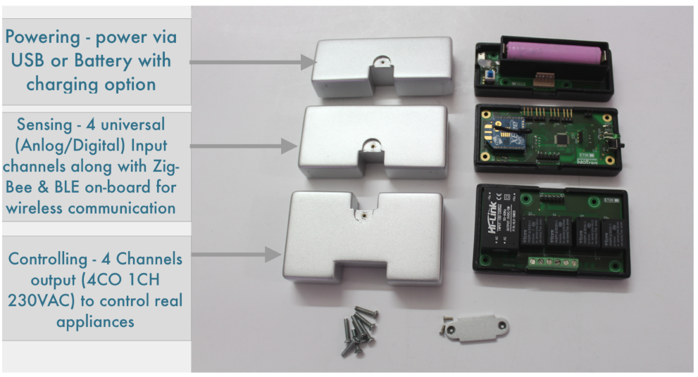
Hi-Node
Hi-Node is a battery (2700 mAh Li-ion) or USB [Optional] powered wireless node which comes with 4 output channels to control real-world devices using 4 relays (Output 5A 230VAC) with 4 connectors and 4 universal (Analog/Digital) input channels to communicate with real-world sensors and transmit this information to IoT gateway using wireless (Zig-bee & BLE4.0) protocols.
Hi-Node
Hi-Node provides standard interface that offers not only remote monitoring but also control capability for managing many types of devices and it also offers advanced Edge Analytics & Local storage. The Hi-Node ZigBee is based on the Digikey Wired XBee module which boasts a range of about 80 – 100 meters line of sight and about 40 meters indoor. The Hi-Node is based around the ATmega328P with 2KB of SRAM, 32KB of Flash memory, and 1KB of EEPROM.
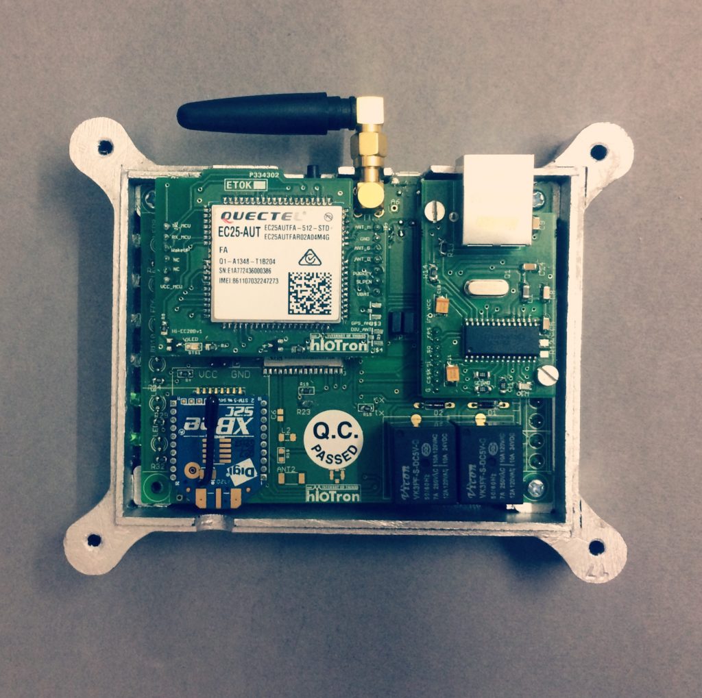
Hi-Gate
Hi-Gate is the brain of this kit which is fully Modular & Enterprise IoT gateway and which doesn’t only translate the protocol [RF/ NON-RF –To– REST/MQTT] but has TI CC3200 at its heart. The Gateway device comes with Zig-Bee and BLE4.0 to support its local network infrastructure with the Hi-Nodes and an outbound connectivity for connecting to the outside world using Wi-Fi 802.11 B/G/N Radio, Ethernet, and Cellular connectivity (2G, 3G, and 4G).
Hi-Gate
The Gateway device supports dual mode of operation – As a Node or Gateway. The Hi-Gate can support up to 25 wireless Hi-Nodes and offers an auto-reconnect for Wi-Fi and GSM network.
The following are the specification of the Hi-Gate:
Hardware System
Controller: ARM Cortex-M4 Core at 80 MHz
Flash: 1MB Serial Flash Memory
RAM: 256KB
EEPROM: 512KB External
Interface
Power input: 9-12V DC
2-GPIO Port Pins
2-Analog Port Pins
RTC
WiFi Specs
IEEE 802.11 b/g/n
Frequency Band: 2.4 ~ 2.462 GHz
HioTron IoT Platform
The hIOTron IoT Platform supports five major D’s such as Device Management, Device Connectivity, Data Storage, Data Analytics and Dashboard/Application enabled for the management of an IoT project life cycle. The Hi-Gate stream data to the hIOTron platform where all the analytics, storage, automation will be carried out.
The Hiotron IOT Platform
Dashboard & Mobile App
You can monitor & control your project application through the Dashboard & Mobile Application provide by HioTron and do unlimited customization from anywhere, anytime.
The Modular & Enterprise IoT development kit comes in 3 versions are Standard, Advance & Customizedwhich can be selected based on applications requirement. The kit pricing is currently not disclosed. More information about the Kit can be found here and for more details on about getting started with the kit can be found here.
The researchers at Soochow University in China, have published a paper on the hybrid device that is able to harness the power of sun and rain using a hybrid panel. By attaching a transparent nanogenerator to a silicon solar cell, researchers have designed a device that harvests solar energy in sunny conditions and the mechanical energy of falling raindrops in rainy conditions. The dual functionality of this hybrid panel may provide a way to collect energy with greater efficiency in the midst of constantly changing weather conditions.
The hybrid solar panel can generate power fro rain too
The hybrid device consists of a conventional silicon solar cell and a Triboelectric Nanogenerator (TENG), which turns the mechanical energy of falling raindrops into electricity. Although previous research has shown that these two types of devices can be connected with an extra wire, in the new design the solar cell and TENG are integrated by sharing a mutual electrode.
The biggest breakthrough in this work is that an integrated generator composed of a solar cell and a TENG was demonstrated through sharing a mutual electrode,
Zhen Wen at Soochow University said,
Compared to previous work, the simple design of the mutual electrode reduces the number of functional layers, which greatly improves the output efficiency.
The mutual electrode not only results in a more compact design, but it also offers advantages to both the solar cell and TENG. In particular, the TENG protects the solar cell by acting as a waterproof barrier and prevents water from penetrating the silicon. The textured electrode surface also greatly overcomes unwanted reflection of light, enhancing light harvesting of the solar panel. The textured surface results in a greater contact area between the TENG and falling raindrops, which improves the overall performance of the nanogenerator.
Due to the unique design, it has advantages of being lightweight and having a high efficiency, The team is now designing a fiber-shaped device and expect to weave them together as a fabric. In near future, it is possible to fabricate such clothing that can generate electricity from sunshine and raindrops, and then use this electricity to power wearable electronic devices.
Hi guys, welcome to today’s tutorial. Today we will look at how to use a hall effect sensor with Arduino.
A hall effect sensor is a sensor that varies its output based on the presence or absence of a magnetic field. This means that the output signal produced by a Hall effect sensor is a function of magnetic field density around it. When the magnetic flux density around it exceeds a certain pre-set threshold value, the sensor detects it and generates an output voltage sometimes called the hall voltage to indicate the presence of the magnetic field.
Hall sensors are becoming very popular due to their versatility and they are used in many different applications. One of the popular applications of hall effect sensors is in automotive systems where they are used to detect position, measure distance and speed. They are also used in modern devices like smartphones and computers and also used in different type of switches where the presence of a magnetic field is used to either activate or deactivate a circuit.
Hi guys, welcome to today’s tutorial. Today we will look at how to use a hall effect sensor with Arduino.
A hall effect sensor is a sensor that varies its output based on the presence or absence of a magnetic field. This means that the output signal produced by a Hall effect sensor is a function of magnetic field density around it. When the magnetic flux density around it exceeds a certain pre-set threshold value, the sensor detects it and generates an output voltage sometimes called the hall voltage to indicate the presence of the magnetic field.
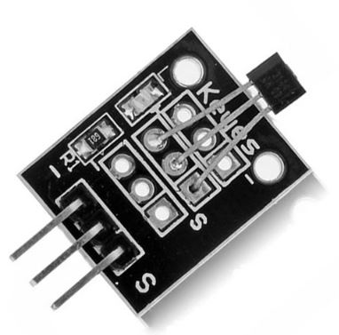
Hall Effect Sensor
Hall sensors are becoming very popular due to their versatility and they are used in many different applications. One of the popular applications of hall effect sensors is in automotive systems where they are used to detect position, measure distance and speed. They are also used in modern devices like smartphones and computers and also used in different type of switches where the presence of a magnetic field is used to either activate or deactivate a circuit.
Hall sensors produce either analog or digital output depending on the particular sensor. Whichever type, they usually come in a three pin package with one pin to represent signal and the other two to provide power to the sensor. This makes easy the connection to any microcontroller.
For today’s tutorial, we will demonstrate how the hall effect sensor works by connecting it alongside a LED to an Arduino. The Arduino will be programmed such that when a magnet is brought close to the hall effect sensor, the LED comes on and when the magnet is removed, it goes off.
Required Components
The following components are required to build this project.
As usual, the exact components used for this tutorial can be bought via the links attached to each of the components listed above.
Schematics
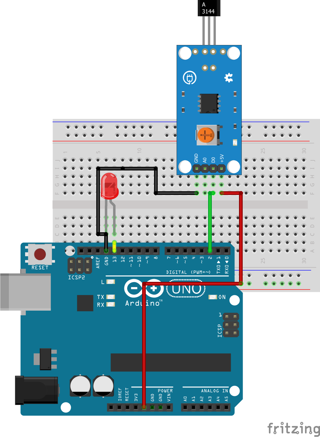
The schematic for this project is a simple one, as all we have to do is connect the three pins of the hall sensor and an LED to the Arduino. Connect the components as shown in the schematics below.
Schematics
The connection is further described below to make it easy to follow.
Hall Sensor – Arduino
VCC - 5V
GND - GND
SIG - D2
The LED can be plugged directly into the Arduino with the positive leg in Arduino pin 13 and the other leg plugged into the ground pin without a resistor because arduino has an internal resistor attached to pin 13.
With the schematics done, we can proceed to the code for this project.
Code
The code for this project is really simple, all we want to do as earlier mentioned is to check if a magnetic field is being sensed and if yes, turn on the LED if no, we turn off the LED.
To do a short explanation of the code for this project, the first thing we do is declare the pins of the Arduino to which our hall sensor and LED is connected, after which we create a variable “state” which will store the value from the hall sensor.
   //////////////////////////////////////////////
  //        HALL EFFECT SENSOR DEMO           //
 //          Author: Nick Koumaris           //
//           http://www.educ8s.tv           //
/////////////////////////////////////////////

int hallSensorPin = 2;
int ledPin =  13;
int state = 0;
Next, we proceed to the void setup function where we declare the pin mode for the pins of the Arduino to which the LED and the Hall sensor are connected.
Next is the void loop function, the task here is the same as if we want to use a push button to control an LED with an Arduino in between. We read the output of the hall sensor and store in a variable named state. When the value is LOW, we turn the LED, HIGH and when the value is high, we turn the LED Low. The configuration of your hall sensor may be different as the sensor may turn High when a magnetic field is detected. This should be confirmed on the sensor’s datasheet.
void loop(){
state = digitalRead(hallSensorPin);
if (state == LOW) {
digitalWrite(ledPin, HIGH);
}
else {
digitalWrite(ledPin, LOW);
}
}
The complete code for this project is shown below and also available for download under the download section at the end of this tutorial.
//////////////////////////////////////////////
// HALL EFFECT SENSOR DEMO //
// //
// http://www.educ8s.tv //
/////////////////////////////////////////////
int hallSensorPin = 2;
int ledPin = 13;
int state = 0;
void setup() {
  pinMode(ledPin, OUTPUT);
  pinMode(hallSensorPin, INPUT);
}
void loop(){

  state = digitalRead(hallSensorPin);

  if (state == LOW) {
    digitalWrite(ledPin, HIGH);
  }
  else {
    digitalWrite(ledPin, LOW);
  }
}
Demo
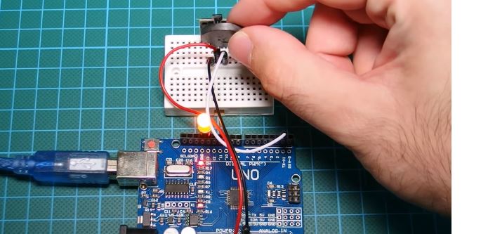
Copy the code and upload to your Arduino board. You should see the LED switch when a magnet is brought close to it as shown in the image below.
Demo
That’s it for this tutorial guys, thanks for following, If you have any questions as regards this tutorial, do not hesitate to drop it under the comment section of this tutorial. I will be glad to help.
The video version of this tutorial on youtube is here:
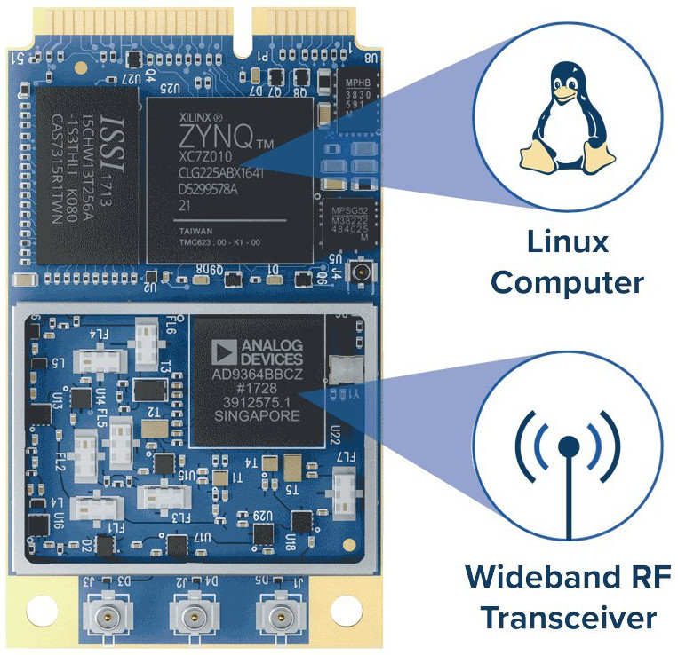
Epiq Solutions, a company from the USA, has included a new member of its Sidekiq line of Software-defined radio (SDR) add-on cards called the Sidekiq Z2. Dimensions of this card are only 51 x 30 x 5mm, the size of a full-size mini-PCIe card, the Sidekiq Z2 computer-on-module is advertised as “the world’s smallest wideband RF transceiver + Linux computer in a product-ready module”. The module is most suitable for handheld RF testing and measurement, remote RF sensing, wireless security applications, and CubeSat/UAS datalinks. A carrier board is also available with this module.
Sidekiq Z2 SDR Module
Unlike previous Sidekiq cards, the Sidekiq Z2 can act as a standalone computer, running Linux on a Xilinx Zynq-7000 series Arm/FPGA SoC. Like the original Sidekiq, which is available in mini-PCIe or M.2 form factors, the Sidekiq Z2 operates at 70MHz to 6GHz. There’s also a Sidekiq X2, which uses the VITA57.1 FMC form factor, which supports 1MHz to 6GHz frequencies.
Epiq claims, the new Sidekiq Z2 can boot Linux in under two seconds, with a typical system power consumption under 2 Watts. The Zynq comes with 512MB DDR3L RAM and 32MB QSPI flash. The SoC drives USB 2.0 OTG, serial UART, JTAG, and GPIO signals to a carrier board.
The shielded AD9634 1Rx + 1Tx transceiver has a 4-band Rx pre-select filter bank and an up to 61.44 Msamples/sec sample rate. The 40MHz TCVCXO ref clock features +/- 1 PPM stability. The 3.3V, 8-gram module supports -40 to 85°C temperatures. The module also offers many U.FL antenna connectors.
The company offers a Sidekiq Z2 Evaluation Kit (EVK) that includes two Sidekiq Z2 cards pre-loaded and supported by Analog Devices’ open source IIO reference design, along with two simple carrier cards. An optional Platform Development Kit (PDK) offers enhanced support and an optimized FPGA reference design to maximize processing capability of the FPGA. Epiq Solutions also presents applications for embedded RF spectrum analysis as well as 2G/3G/4G cellular network survey.
The Sidekiq Z2 is available now at a price of $649 for 1,000+ unit orders. The Sidekiq Z2 EVK and PDK also appear to be available, with pricing undisclosed. More information may be found in the Epiq Solutions Sidekiq Z2 announcement and product page.
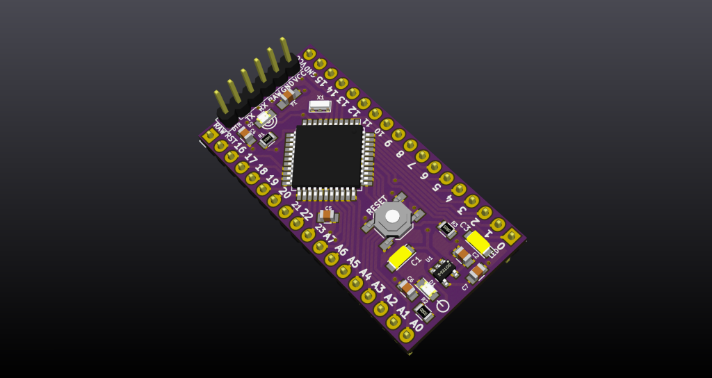
A DIY Arduino type hardware board based on ATmega644p Atmega1284p
This project is free and based on @MCUDude’s MightyCore which has awesome well designed kits for serious development with AVR’s.
Mightyduino is an Arduino with more memory than an Arduino Pro mini. It can use 644p (64k) or 1284p (128k) chips. Its voltage can be configured by U1 and the frequecy can be configured by the Murata’s ressonator (crystal). It has a power led and another one connected to pin D0. The push button performs reset. DTR pin can be used to external reset. The RAW pin is the input voltage <16v. The VCC pin is the regulator output and IC voltage, it can be loaded up to peak of 500mA.