Hi guys, welcome to today’s tutorial. In this tutorial we will look at how to use the TCS230 color sensor with Arduino. To demonstrate the ability of the color sensor, we will build a color detector system capable of detecting the color in front of the sensor and displaying that color on a TFT Display. For this project, we will use the TCS230 color sensor and the color will be displayed on the ST7735 1.8″ TFT Display.
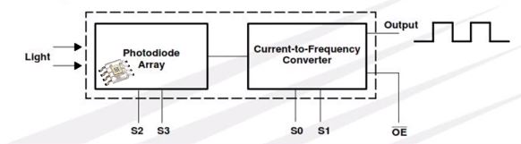
The TCS230 is a programmable color light-to-frequency converter which combines configurable silicon photodiodes and a current-to-frequency converter on a single monolithic CMOS integrated circuit.
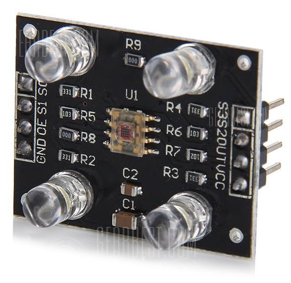
The color sensor module is made up of the color sensor itself and four Infrared LEDs which are used to illuminate any object placed in front of the sensor to ensure the readings are accurate and are not affected by the surrounding illumination. The sensor is made up of an array of photodiodes with color filters for red, blue, green and a clear filter on top.
Color Detector Using TCS230 Color sensor and Arduino – [Link]
Hi guys, welcome to today’s tutorial. In this tutorial we will look at how to use the TCS230 color sensor with Arduino. To demonstrate the ability of the color sensor, we will build a color detector system capable of detecting the color in front of the sensor and displaying that color on a TFT Display. For this project, we will use the TCS230 color sensor and the color will be displayed on the ST7735 1.8″ TFT Display.
The TCS230 is a programmable color light-to-frequency converter which combines configurable silicon photodiodes and a current-to-frequency converter on a single monolithic CMOS integrated circuit.
TCS230 Color Sensor
The color sensor module is made up of the color sensor itself and four Infrared LEDs which are used to illuminate any object placed in front of the sensor to ensure the readings are accurate and are not affected by the surrounding illumination. The sensor is made up of an array of photodiodes with color filters for red, blue, green and a clear filter on top.
The detect a color, the sensor reads an 8×8 array of photodiodes which comprises of 16 photodiodes with blue filters, 16 photodiodes with green filters, 16 photodiodes with red filters, and 16 photodiodes are clear with no filters. The four types (colors) of photodiodes are interdigitated to minimize the effect of non-uniformity of incident irradiance. All 16 photodiodes of the same color are connected in parallel and which type of photodiode the device uses during operation is pin-selectable.
The output of the TCs230 color sensor is a 50% duty cycle square wave whose frequency is proportional to the light intensity of the selected filter.
Required Components
The following components are required to build this project;
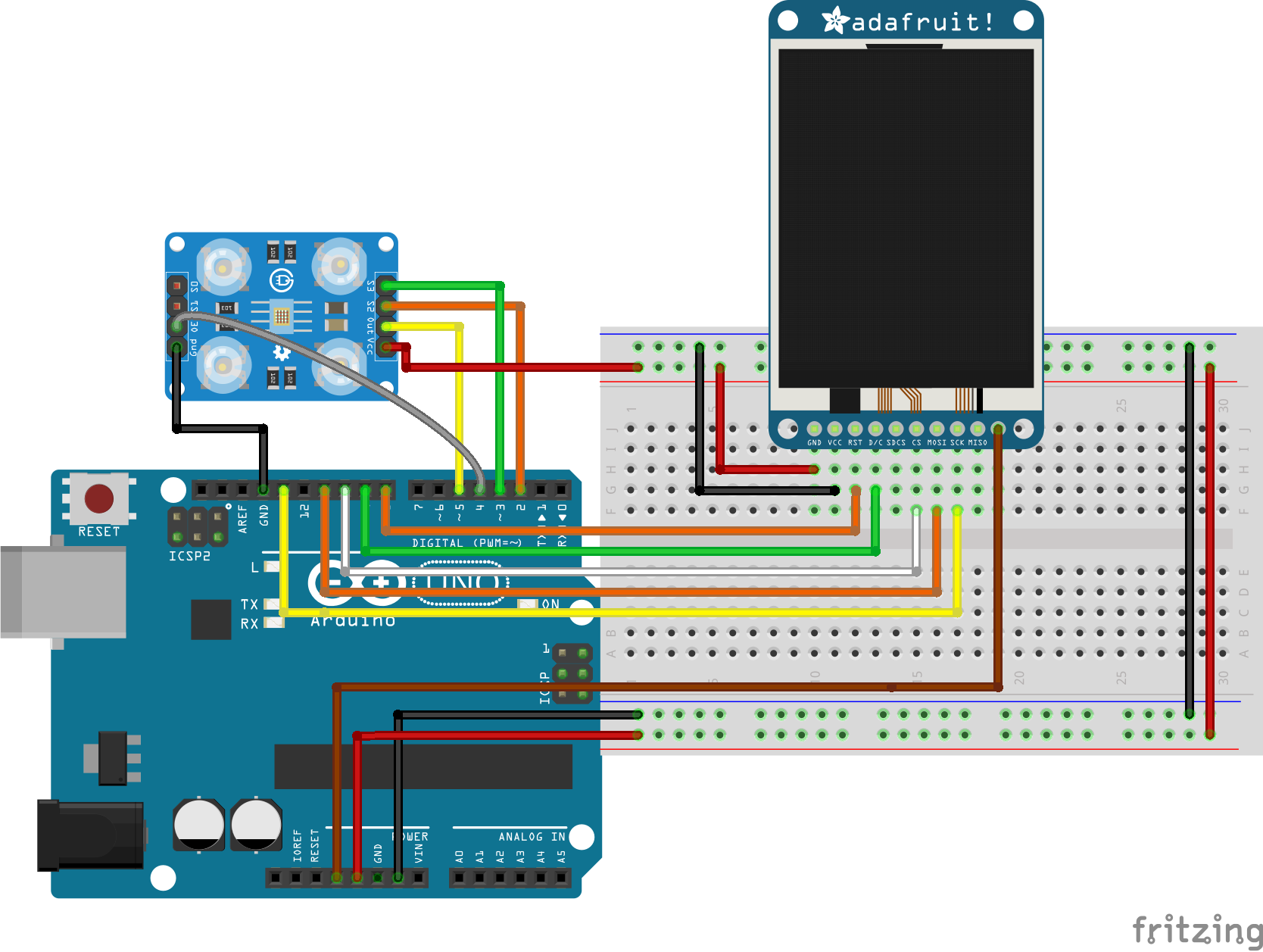
Some TCS230 modules include a LED Pin, if this is the model you have, you should connect the LED pin to the 5V pin of the Arduino.
More information on how to connect and use the ST7735 TFT display has been covered in a previous tutorial here and it may help you understand how the display works.
Go over the schematics once again to ensure everything is rightly connected before moving to the next section.
Code
To easily write the code for this project we need four libraries, two of which are needed to enable us to interface with the color sensor and extract readings while the other two are needed to enable us to use the TFT display. The required libraries are:
Next, we declare the pins of the Arduino to which the CS, DC and RST pins of our display are connected to.
#define cs 10
#define dc 9
#define rst 8
Next, we declare the colors specifying their hex values and we also declare the GPIO pins of the Arduino to which the color sensor pins are connected.
// Color definitions
#define BLACK 0x0000
#define BLUE 0x001F
#define RED 0xF800
#define GREEN 0x07E0
#define CYAN 0x07FF
#define MAGENTA 0xF81F
#define YELLOW 0xFFE0
#define WHITE 0xFFFF
#define GREY 0xC618
// Pin definitions
#define S2_OUT 2
#define S3_OUT 3
#define OE_OUT 4 // LOW = ENABLED
Next, we create three variables to represent red(R), green(G) and blue(B). These variables will capture the color content of the data received by the color sensor.
int R = 0;
int G = 0;
int B = 0;
Next, we create an instance of the Color sensor library and the ST7735 display’s library specifying the required pins.
MD_TCS230 CS(S2_OUT, S3_OUT, OE_OUT);
int state = 0;
Adafruit_ST7735 tft = Adafruit_ST7735(cs, dc, rst);
With all the preliminary jobs done, we then move to the void setup() function, where we initialize the display and display a welcome text. We then start communication with the color sensor.
Next up is the void loop function. The first thing we do under this function is to calibrate the color sensor by feeding it Black and white colors, once our project recognizes these colors, it’s then calibrated and able to recognize any other color in between.
After the calibration has been done, the state variable becomes greater than zero and the program starts running. From this point the module can read any color fed to it.
The complete code for this project is available below and also included in the zip file under the download section.
 //////////////////////////////////////////////
  //       Arduino Color Sensor Tutorial      //
 //          with ST7735 TFT LCD             //
//           http://www.educ8s.tv           //
/////////////////////////////////////////////

#include <MD_TCS230.h>
#include <FreqCount.h>
#include <Adafruit_ST7735.h>
#include <Adafruit_GFX.h>
#define cs   10
#define dc   9
#define rst  8
// Color definitions
#define BLACK    0x0000
#define BLUE     0x001F
#define RED      0xF800
#define GREEN    0x07E0
#define CYAN     0x07FF
#define MAGENTA  0xF81F
#define YELLOW   0xFFE0
#define WHITE    0xFFFF
#define GREY     0xC618

// Pin definitions
#define  S2_OUT  2
#define  S3_OUT  3
#define  OE_OUT   4    // LOW = ENABLED
int R = 0;
int G = 0;
int B = 0;
MD_TCS230 CS(S2_OUT, S3_OUT, OE_OUT);

int state = 0;

Adafruit_ST7735 tft = Adafruit_ST7735(cs, dc, rst);
void setup() {

  Serial.begin(57600);

  tft.initR(INITR_BLACKTAB);   // initialize a ST7735S chip, black tab

  drawBlackScreen();

  tft.setCursor(20,30);
  tft.setTextColor(RED);
  tft.setTextSize(2);
  tft.print("Color");

  tft.setCursor(20,60);
  tft.setTextColor(GREEN);
  tft.setTextSize(2);
  tft.print("Sensor");

  tft.setCursor(20,90);
  tft.setTextColor(BLUE);
  tft.setTextSize(2);
  tft.print("Tutorial");

  delay(3000);

  drawBlackScreen();

   tft.setCursor(10,30);
   tft.setTextColor(WHITE);
   tft.setTextSize(2);
   tft.print("SET BLACK");
   delay(5000);

   CS.begin();
   CS.read();
}
void loop() {

if(state ==0)
{
  if (CS.available()) {
   sensorData  sd;
   CS.getRaw(&sd);
   CS.setDarkCal(&sd);
   Serial.println("Black Calibration Set");
   state++;
   drawBlackScreen();

   tft.setCursor(10,30);
   tft.setTextColor(WHITE);
   tft.setTextSize(2);
   tft.print("SET WHITE");

   delay(5000);
   CS.read();
  }
}
else if(state == 1)
{
if (CS.available()) {
sensorData sd;
CS.getRaw(&sd);
CS.setWhiteCal(&sd);
Serial.println("White Calibration Set");
drawBlackScreen();
tft.setCursor(35,30);
tft.setTextColor(WHITE);
tft.setTextSize(2);
tft.print("COLOR");
tft.drawRect(30,70,70,60,WHITE);
state++;
}
}else
{
readSensor();
}
}
void drawBlackScreen()
{
tft.fillScreen(BLACK);
//Draw white frame
tft.drawRect(0,0,127,159,WHITE);
tft.drawRect(1,1,127,159,WHITE);
}
uint16_t convertRGB24toRGB565(uint8_t r, uint8_t g, uint8_t b)
{
return ((r / 8) << 11) | ((g / 4) << 5) | (b / 8);
}
void readSensor()
{
static bool waiting = false;
if (!waiting)
{
CS.read();
waiting = true;
}
else
{
if (CS.available())
{
colorData rgb;
CS.getRGB(&rgb);
Serial.print("RGB [");
Serial.print(rgb.value[TCS230_RGB_R]);
Serial.print(",");
Serial.print(rgb.value[TCS230_RGB_G]);
Serial.print(",");
Serial.print(rgb.value[TCS230_RGB_B]);
Serial.println("]");
R = rgb.value[TCS230_RGB_R];
G = rgb.value[TCS230_RGB_G];
B = rgb.value[TCS230_RGB_B];
int color = convertRGB24toRGB565(R,G,B); //Convertion to 16bit color for the display
delay(100);
tft.fillRect(31,71,68,58,color);
waiting = false;
}
}
}
Demo
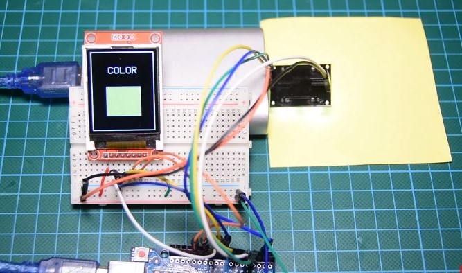
Check your connections once more to be sure everything is correct, then upload the code to the Arduino and put colored paper or any colored material in front of the color sensor. Don’t forget to calibrate the sensor using black and white colors first before feeding it other colors. The image below shows the project recognizing the yellow color.
Demo
Cool right?
That’s it for this tutorial guys, color sorting has several real-life applications and I’m sure it is awesome to know that this can be done with something as cheap as the Arduino. What problem will you solve with this tutorial, let’s get the conversation started. Feel free to reach me via the comment section if you have any questions in regards to the tutorial.
Till next time!
You can watch the video of this tutorial on youtube here
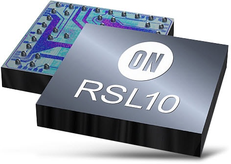
Bringing the industry’s lowest power Bluetooth® low energy technology to IoT with a highly flexible multi-protocol 2,4 GHz radio RSL10 from ON Semiconductor.
RSL10 is a multi-protocol Bluetooth 5 certified radio System on Chip (SoC) which brings ultra-low-power wireless technology to IoT.
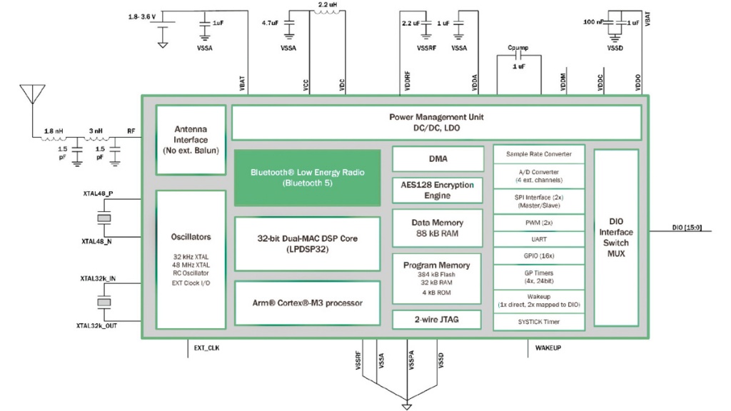
Offering the industry’s lowest power consumption, RSL10 helps provide devices like heart rate monitors with advanced wireless features while optimizing system size and battery life.
Unlike most other multi-protocol radio SoCs, RSL10 is specifically designed for applications using 1.2V and 1.5V batteries, and supports a voltage supply range between 1.1V and 3.3V without a required DC/DC converter. The highly-integrated radio SoC features a dual-core architecture and a 2.4 GHz transceiver, providing the flexibility to support Bluetooth low energy technology and 2.4GHz proprietary or custom protocols.
Features
Ultra-Low-Power:
Industry’s lowest power consumption in Deep Sleep Mode (62.5 nW) and Rx in Receive Mode (7 mW)
Supports Bluetooth low energy and 2.4 GHz proprietary/custom protocols
Supports Firmware Over The Air (FOTA)
Flexible Voltage Supply Range (1.1 and 3.3 V): Supports devices using 1.2 and 1.5 V batteries without a required external DC/DC converter
Ultra-Miniature: RSL10 is offered in a 5.50 mm2 WLCSP and a 6 x 6 mm QFN. For added miniaturization, the radio SoC can be integrated into System-in-Package (SiP) solutions which combine RSL10 with a custom ASIC.
Sophisticated Dual-Core Architecture: Features a programmable ARM Cortex-M3 processor for clocking speeds up to 48 MHz and the flexibility to support 2.4 GHz proprietary and custom protocol stacks. An embedded Digital Signal Processor (DSP) enables signal processing intensive applications, such as wireless audio codecs.
On-Chip and Software Wireless Support: Features a 2.4 GHz Radio Frequency Front-End (RFFE) and a Bluetooth 5 certified baseband controller which supports 2 Mbps data rates. A wide range of supported Bluetooth low energy protocols are provided in the RSL10 development tools kit.
Highly-Integrated System-on-Chip (SoC): The powerful dual-core architecture is complemented by high-efficiency power management units, oscillators, flash, and RAM memories, a DMA controller, and peripherals and interfaces.
Other Key Technical Features:
384 kB of flash memory
IP protection feature to secure flash contents
Configurable analog and digital sensor interfaces (GPIOs, LSADs, I2C, SPI, PCM)
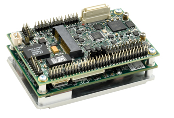
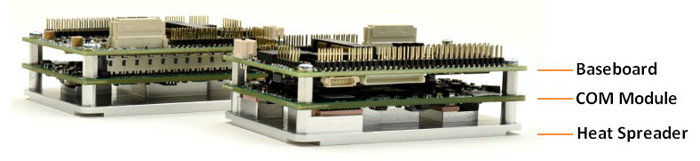
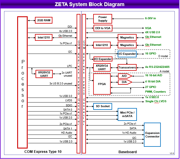
Zeta is a Single Board Computer (SBC) from Diamond Systems that combines a COM Express Mini Type 10 module based on Apollo Lake or Bay Trail SoCs with a DAQ-rich carrier, and a heat spreader mounted below. The Zeta COM Express Mini Type 10 supports the quad-core Atom E3940 and Pentium N4200 from Intel’s Apollo Lake generation, as well as a dual-core Atom E3825 from the earlier Bay Trail family. Measures 84mm by 55mm, Diamond, Creators of Zeta do not promote their creation as a standalone Computer -on-Module product mostly because of its extra add-ons and functionality.
Diamond Systems Zeta
According to Diamond, the 84 x 55mm Zeta offers functionality and performance equivalent to Diamond’s Bay Trail-based Aries PC/104 SBC, at just 40 percent of its 116 x 102mm size.
The Zeta processor choice can be obtained in two Stock Keeping Units (SKUs), one has 16x DIO lines while the other has an FPGA-driven data acquisition circuit that replaces the 16x DIO with a 27x DIO connector. The second SKU also adds 4x channels of 16-bit digital outputs, eight 32-bit timers, 16x channels of 16-bit analog inputs among other features.
The Zeta offers 2GB, 4GB, or 8GB RAM depending on the type of processor chosen. There’s also a microSD slot, as well as a mini-PCI express slot with mSATA support. Standard features include 2x GbE, VGA, LVDS, USB 3.0, 4x USB 2.0, and 4x RS-232/422/485. It also comes with an optional daughter board to act as an expansion set. The daughter board has a full-size mini-PCI express slot, an M.2 M-key 2242 for an SSD, and audio I/O.
General Specifications for the Zeta Serial Board Controller are:
Processor — Intel Apollo Lake or Bay Trail:
Atom x5-E3940 — 4x Apollo Lake cores @ 1.6GHz/1.8GHz; 9W TDP
Pentium N4200 — 4x Apollo Lake cores @ 1.1GHz/2.5GHz; 6W TDP
Atom E3825 — 2x Bay Trail cores @ 1.33GHz; 6W TDP
Memory & Storage:
2GB (E3825), 4GB (E3940) or 8GB (N4200) RAM
MicroSD slot (bootable for Linux)
mSATA via mini-PCIe slot
M.2 M-key 2242 for SSD on an optional daughterboard
Display — VGA; LVDS
Networking — 2x Gigabit Ethernet
Expansion Options:
Mini-PCIe slot with PCIe, USB, and mSATA support.
Expansion daughterboard:
Full-size mini-PCIe slot with PCIe and USB
HD audio (Realtek ALC892) line-in, mic-in, line-out
16x DIO (via I2C) with configurable 3.3V/ 5V logic levels and Pull-up/down resistors
Other I/O:
USB 3.0
4x USB 2.0
4x RS-232/422/485 (software-programmable with termination)
16x DIO with selectable 3.3V/5V logic levels
Optional DAQ circuit (separate SKU):
27x DIO with selectable 3.3V/5V logic levels (replaces original 16x DIO)
16x 16-bit analog inputs
+/-10V, +/-5V, 0-10V, and 0-5V input ranges
100KHz max sample rate with 2048-sample FIFO
8x differential voltage inputs
4x channels of 16-bit analog outputs
8x 32-bit counter/timers.
4x 24-bit PWMs
Power — Optional 9-36V input
Operating temperature — -40°C to 85°C
Dimensions — 84mm x 55mm (COM Express Mini Type 10)
Operating system — supports Linux (Ubuntu 16.04) and Windows 10 IoT with optional SDKs
Other features — watchdog; heat spreader; dev kit version with cables and SDKs
Block Diagram
Zeta’s small size and high feature density make it an ideal choice for mobile applications. It stands ready to meet the challenges of these environments with a wide range 6-36VDC input voltage, a -40 to +85°C operating temperature range, and fanless heat spreader cooling (heat sink options are available). Zeta is available for order online at an undisclosed price. More information for the Diamond Systems Zeta can be found on the product page.
Octavo Systems back in 2017 released their OSD335x-SM System-In-Package device, a powerful ARM Cortex®-A8 SIP-based package. The OSD335x-SM was a device of its class, measured at just 21mm x 21mm, and the OSD335x-SM is the smallest AM335x processor-based module on the market today that still allows complete access to all the AM335x device I/Os including PRUs. The OSD335x-SM helps in removing the need for DDR routing, power sequencing, complex supply chains and even the need for building larger PCBs to accommodate several components.
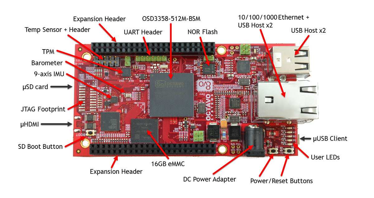
Octavo has announced the availability of the OSD3358-SM-RED platform. The OSD3358-SM-RED platform is the official Reference, Evaluation, and Development platform for the OSD335x-SM SiP family. It is designed by Octavo Systems to allow users to evaluate the OSD335x-SM SiP for their application quickly.
The OSD3358-SM-RED is fully designed around the OSD335x-SM SiP at its core, thus inheriting all the features of the SiP device. The OSD335x-SM integrates a powerful 1GHz Texas Instruments Sitara AM335x processor, DDR3 Memory, two power supplies, and passives into a single easy to use package. The 256 Ball BGA is 60% smaller than an equivalent design using discrete devices, making it the smallest ARM Cortex-A8 system implementation.
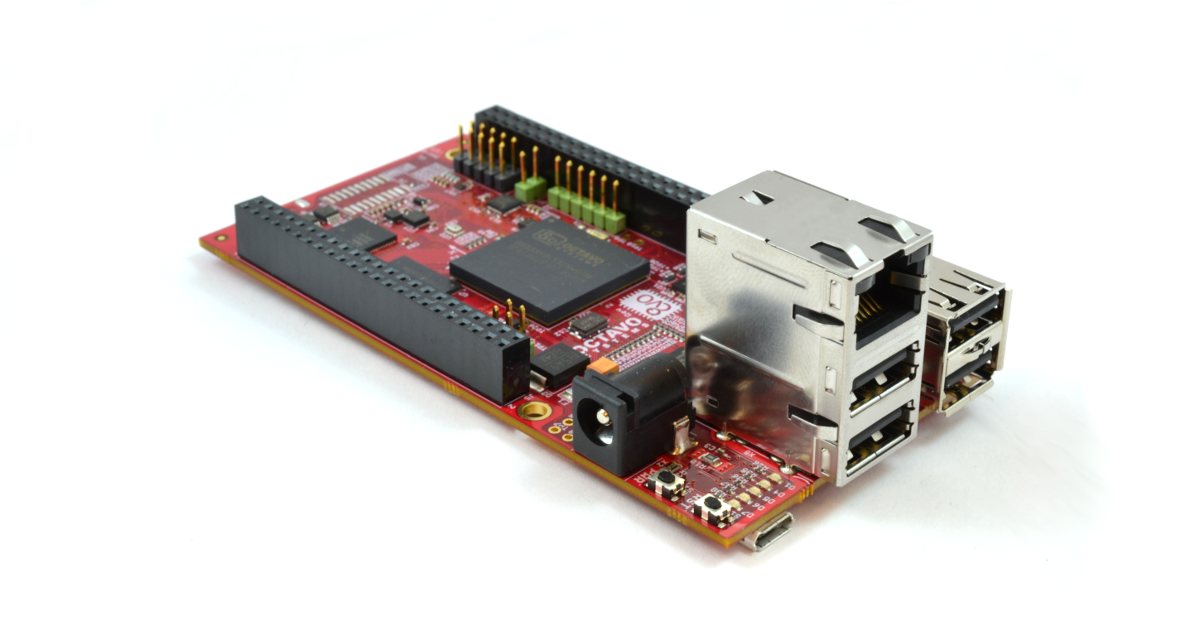
The development board comes included with a Gigabyte Ethernet (10/100/1000 Ethernet), a whopping 5 USB 2.o ports (comes with 4 USB hub ports and 1 micro USB client port), a micro HDMI for display, and two 46 pin expansion headers which makes it compatible with the Beaglebone ecosystem. The OSD3358-SM-RED has a 16GB eMMC on board and a microSD card interface.
The board also adds some onboard sensors providing a possible real-world case study. It comes with a 9-axis IMU that provides acceleration, gyroscope, and magnetometer data; a barometer to provide altitude; and a multi-channel temperature sensor.
Even though the SM-RED shares some compatibility with the BeagleBone it has no onboard WiFi and Bluetooth, but there’s an Ethernet port, and unlike the BB Black and other BeagleBone variants, it’s a GbE port. You also get 16GB eMMC compared to 4GB on the other BeagleBones.
The following are the specifications for the OSD3358-SM-RED:
Processor — TI Sitara AM335x (1x Cortex-A8 @ 1GHz)
PowerVR SGX530 GPU
32-bit 200MHz Cortex-M3 based programmable real-time units (PRUs)
Memory — 512MB DDR3 RAM
Storage — 16GB eMMC
microSD slot with card pre-installed with Debian and drivers
Display — Micro-HDMI port
Networking — 10/100/1000 Ethernet port
Other I/O:
4x USB 2.0 host/device ports
Micro-USB client port
UART and JTAG
2x BeagleBone Black Cape compatible expansion connectors
Other features — 9-axis IMU
Barometer and temperature sensors
4x LEDs
TPM and secure NOR (currently not supported)
Power — 5V input
LiPo battery connector
Power and reset buttons
PMIC (via OSD3358 SiP)
Dimensions – 108 x 54 x 32mm
Operating system — Debian Linux
The OSD3358-SM-RED platform comes pre-loaded with a Debian Linux distribution complete with driver libraries for the different sensors on the board. All of the design files are freely available and can be used as a known good starting point for new designs. The OSD3358-SM-RED is available from Octavo Systems, Digi-Key, and Mouser for $199. More information may be found on Octavo’s OSD3358-SM-RED product and shopping page.
The LMZM33603 36V, 3A power module offers stellar EMI performance in a compact QFN package.
Order yours today and enjoy the peace of mind that comes with reliable performance, small solution size, and reduced design cycle time.
Powering high-current processors requires flexible solutions, and the TPS53681 PMBus multiphase PWM buck controller delivers with dual output 6+2/5+3 phase configuration. This multiphase driverless controller is paired with TI smart power stages for accurate current sensing and excellent thermal performance.
With a 94% smaller footprint, lower leakage and flat-clamping technology, TI’s Flat-Clamp portfolio provides more robust protection than traditional TVS surge diodes.
TI’s new TVS3300 family of Flat-Clamps gives designers precise control over clamping voltage vs surge current, even across temperature. It’s time to re-evaluate your TVS protection. Learn more in the whitepaper.
Powering your 4A to 8A digital load just got smaller, easier, and more reliable. At 7.5mm x 7.5mm, the TPSM84824 17V, 8A step-down power module provides the smallest footprint in its class. And with TurboTrans™ technology, it delivers fast transient response with the industry’s lowest overshoot.
TPSM84824 comes with minimal external components, and pin- and footprint-compatible 4A and 6A alternatives.
Presenting an easier way to power your high-current digital core: TPSM846C23 is a PMBus-compliant DC/DC power module with an integrated inductor and FETs that crams 35A of output current capability into 240mm2. Two of these modules can easily be paralleled to deliver up to 70A of output current to the point-of-load from a nominal 12V or 5V input voltage.
The TPS5516x-Q1 family provides a cost-effective single chip solution for a regulated output voltage between 5V and 12V, with up to 1A load current depending on voltage requirements. The buck-boost overlap control ensures automatic transition between step-down and step-up mode with optimal efficiency.
These buck/boosts provide a smaller solution size and higher efficiency than a discrete boost-buck converter solution.
Want the lowest standby power? Need to simplify your system design for your AC/DC applications? Get to know our newest power factor correction (PFC) controller, UCC28056. With zero cross detection scheme (without auxiliary winding) and advanced burst mode, UCC28056 will help you design your next offline system.
TI’s BQ25910, the industry’s first integrated 6A three-level buck battery charger, is a game-changer for how we will charge our smartphones, tablets, electronic point of sale (EPOS) and other portable electronics in the future. New power conversion technology reduces battery charging time up to 50% and allows for up to 5% efficiency improvements compared to conventional architectures.
Any engineers out there looking for high-efficiency DC/DC conversion without the headaches that typically come with EMI mitigation and thermal management? Everyone? Ok, good.
Introducing the LM73605/6 and LM76002/3 families of wide VINsynchronous buck converters. Designed with high integration, thoughtful pin-out, and best-in-class thermal coefficients, LM73605/6 and LM76002/3 give you amazing performance without all of the headaches.
With a 27mm2 package size and only two external components, the LMZM23600/ 01 power module can convert a nominal 24V input to 3.3V in a solution size that is 45% smaller than competition. With the simplicity of power modules paired with the magic of WEBENCH®, you can bring the world’s tiniest 36V, 1A buck design to market with blazing speed.
To find the best price for Texas Instruments search OEMsecrets
In the last few years, we have seen that the Makers’ Movement is growing quite strong, more makers, innovators, and hardware startups are beginning to come up. We saw back in 2015, the most famous hardware prototyping board “The Arduino” is now assembled in the USA as compared to it being manufactured only in Italy, this not only increases the number of Arduinos but also broadens up the whole hardware ecosystems. Remember Pebble Time? The guys that broke the Kickstarter record, they received $1 million in 49 minutes, breaking a current record, and became the most funded Kickstarter to date, reaching $20.4M dollars all the way to its deadline, from over 78,741 backers.
It’s one thing to have an idea, and it’s another thing to get it to people that need it. One of the challenges of getting a crafted idea to users is “Funds,” you need quite some level of funds to mass produce your product and sell it out to users. While the big corporations have the necessary funding and resources, most hardware projects are developed by individuals or small startups and don’t necessarily have such funds available. Projects that are just starting out sometimes need a financial boost to get things going, and most won’t get backing from a VC or angel investor the first time, but perhaps crowdfunding platforms could help here. Crowdfunding is where you get a lot of people to invest in your idea, rather than finding one person to come up with everything you need.
In this post, I will highlight some of the go-to platforms to get funding for your hardware projects and boards easily. Note – I am not affiliated with any of these platforms (at least for now).
Kickstarter
Kickstarter is the most well-known name in crowdfunding and arguably the most active platform, raising over $2 billion since its launch in 2009. Kickstarter is geared more toward creative projects like a new album or writing a book, as well as products and inventions like a personal single-wheel vehicle or a pocket-sized solar charger.
Kickstarter has been one of the significant go-to platforms for hardware-focused products, and we have seen a lot of projects that came to life as a result of there fully funded campaigns on Kickstarter. Kickstarter favors creative project from wearables, smart glasses, drones to robots have been funded on Kickstarter.
Kickstarter isn’t geared towards individuals that have a product they want to release but startups/companies that can manage the whole product cycle and value chain. So, if you have a working product (an MVP preferable and not just a prototype) Kickstarter might be the platform to get the money rolling.
Here’s another vital caveat with Kickstarter: If you don’t raise 100% of your goal, you get none of that cash. Your project needs to be 100% funded for you to collect that money. If you meet your goal? Kickstarter has a 5% fee, and the payment processor will charge an additional 3-5 percent.
IndieGoGo
IndieGoGo is another familiar crowdfunding platform which shares similar traits with Kickstarter. Even though Indiegogo can be used for all sort of projects from profits to non-profits, you can still fund your focused hardware projects on them, and quite many hardware projects have been funded here.
One major difference between Kickstarter and Indiegogo is the funding flexibility. Kickstarter requires you to reach your target to get the funds but IndieGoGo offers flexible funding, which means you get to keep the funds you raised, even if you didn’t reach your goal, of course, this comes at a price of an increased fee. The fee for either is 5% (fixed and flexible), but if you don’t hit your goal with a flexible funding campaign, you’ll pay a higher fee (which is reportedly 9%). There’s no fee for a fixed funding campaign if you don’t hit your goal. And, of course, there will be additional fees (usually around 3%) from payment processors.
IndieGoGo might be your go-to platform if you aren’t sure of getting the exact money you need and feels any funding will do.
CrowdSupply
CrowdSupply is a crowdfunding platform that has a high preference for hardware projects and boasts “over twice the success rate of Kickstarter and Indiegogo.” On crowd supply, you can create a campaign for any hardware projects, from raw IoT board to a full consumer product. CrowdSupply favors creative projects as well as individuals built projects.
CrowdSupply is my recommended go-to platform for makers, tinkers, and innovators out there with the likelihood of getting your creative project funded very high. Get started with CrowdSupply here.
Tindie
Tindie is a marketplace for makers to fund and sell their hardware creations. It is a DIY Hardware MarketPlace and not a crowdfunding platform, unlike others. Tindie pride itself as a hub where hardware makers can quickly sell their products or prototypes without the overhead required in creating a crowdfunding campaign.
Tindie is excellent if you have a customized hardware creation you want to sell out to the hardware community, it could be a new shield you just built or an addon for the raspberry pi that adds some extra functionality.
Final Words
Going by numbers alone, hardware projects should be a win-win proposition for both entrepreneurs and crowdfunding platforms. Seven of the top ten most-funded projects on Indiegogo are hardware projects. Getting your hardware product to markets is now easier than ever before and now could be the best time to get funded. If you have something nice, chances people will fund you are high if you use one of these platforms.
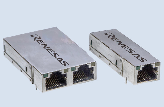
Renesas Electronics Corporation, a significant supplier of advanced semiconductor solutions, announced its latest industrial Ethernet module solution, the I-RJ45. It combines a single- or dual-port RJ45 connector and simplifies integration for industrial Ethernet by supporting various industrial network applications including sensors and transmitters, gateways, operator terminals and remote I/O.
Renesas RJ45 Ethernet Module
This new device is an intelligent RJ45 module that comes with specialized embedded software that supports multiple industrial Ethernet protocol stacks. The software package and sample codes provide system manufacturers with a complete set of tools and frameworks to build their application. This helps to prototype systems, reducing the time needed for industrial network protocol integration. The modules are 50 x 17.5 x 12mm (single) and 50 x 35 x 12mm (dual).
With a general Application Programmable Interface (API), the application can easily be connected to the protocol software. It offers a seamless integration path to other Renesas ASSP solutions. The single-port version of the RJ45 module is based on the RX64M microcontroller (MCU) Group and the dual-port module solution includes the R-IN32M3 industrial Ethernet communication chip.
Renesas also offers a solution kit version of the module that consists of a single or dual-port industrial Ethernet module attached to an adapter board for development. This adapter board enhances the module to connect with Arduino and Pmod interfaces, which enables it to connect to other Renesas MCU development boards including Renesas Synergy™ and RX. The Ethernet module solution kit also includes a quick start-up guide, a USB cable and a CD with software and documentation.
Samples of the I-RJ45 industrial Ethernet module solution are now available worldwide. The mass production is scheduled to begin in Q3, 2018. The industrial Ethernet module solution kit may be available in April 2018 and projected price of €299.00 per kit.
More information is available at the product page of Renesas.
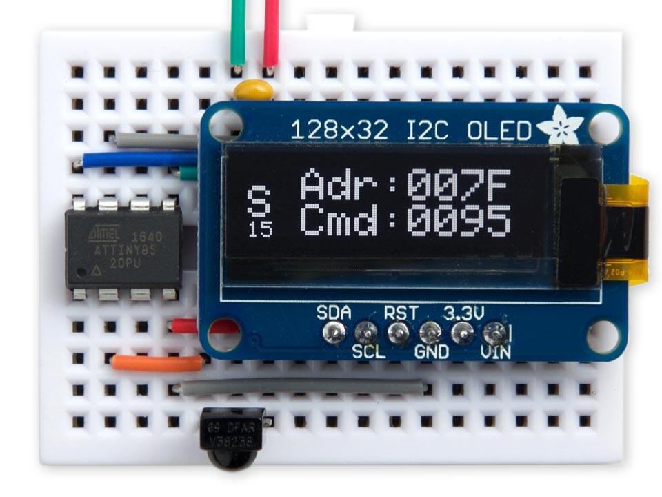
David Johnson-Davies published another great and detailed tutorial on how to build an IR remote control detective. He writes:
The IR Remote Control Detective decodes the signal from several common types of infrared remote control, such as audio, TV, and hobbyist remote controls. To use it you point a remote control at the receiver and press a key; it will then identify the protocol, and display the address and command corresponding to the key.
IR Remote Control Detective based on ATtiny85 – [Link]
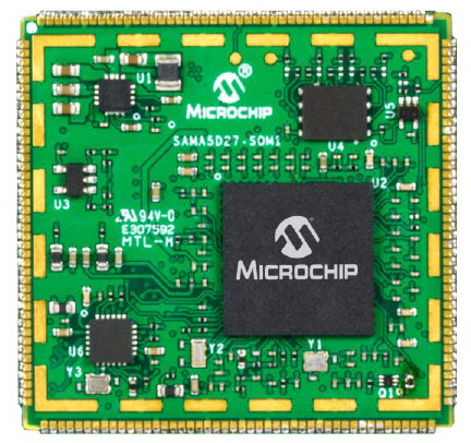
American microcontroller manufacturer company Microchip has unveiled an open source, mainline Linux ready “SAMA5D27 SOM” module. This module is based on a SiP implementation of its Cortex-A5-based SAMA5D27 SoC with 128MB RAM. The 40 x 38mm module is also compatible with a SOM1-EK1 dev board.
SAMA5D27 SOM1
SAMA5D27 SOM1
The SAMA5D27 SOM is Microchip’s first computer-on-module based on a Linux-ready application processor, and the first SiP-based module built around a SAMA5 SoC. It is mainly designed for rugged IoT applications and the module can be soldered onto a baseboard for versatile ease of use. It offers long-term availability and supports industrial grade -40 to 85°C temperature range.
The SAMA5D27 SOM1 combines the RAM-ready SAMA5D27C-D1G SiP with 64Mb of non-volatile QSPI boot flash and a 10/100 Ethernet PHY. The module also integrates a 2Kb EEPROM with pre-programmed MAC address. The SOM is further equipped with a PMIC and a 3.3V power supply. Typical power consumption ranges from 120mA to 160mA. There’s also a 60mA idle mode and an ultra-low 30mA mode.
This module has 128 GPIO pins including 2x USB 2.0 host, one USB device, and 2x SD/MMC interfaces with eMMC 4.51 support. There is also support for 10x UART, 7x SPI, 2x CAN, camera and audio interfaces, and much more.
Like the Xplained boards, the module is open source, from the mainline Linux support to the posting of open schematics, design, Gerber, and BoM files for both the SOM and the optional SOM1-EK1 development board.
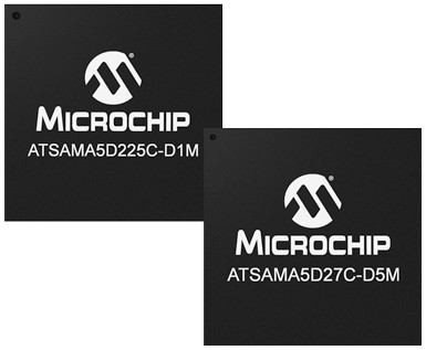
SAMA5D2 SiP
SAMA5D2 SiP
The newly launched SAMA5D2 SiP is built around the Microchip SAMA5D2. The FreeRTOS-focused 128MB version uses a lower-end SAM5D22 model limited to 16-bit DDR2 RAM while the Linux-ready 512MB and 1GB versions use the higher end SAMA5D27 and SAMA5D28, respectively, with 16/32-bit DDR. All the models are renowned for offering CAN support, and because the SAMA5D28 also adds security features, it’s the only one that is pre-certified for PCI Security.
The SAMA5D has fewer I/O pins and slower performance (166-500MHz) compared to the earlier, 600MHz SAMA5D4, but the power consumption is significantly lower. The SAMA5D2 SoC can run at less than 150mW in active mode at 500MHz with all peripherals activated, and at less than 0.5mW in low power mode with SRAM and registers retention.
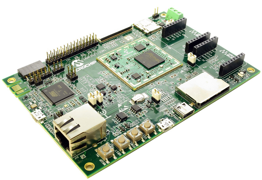
SOM1-EK1 development board
SOM1-EK1 Development Board
The SAMA5D27-SOM1-EK1 development kit is built around a baseboard with a soldered SAMA5D27-SOM1 module with the 128MB (1Gb) configuration. This board is enhanced with SD and microSD slots, as well as a 10/100 Ethernet port, a micro-USB host port, and a micro-USB device port with power input.
Additional I/O option for this dev board includes USB HSIC, CAN, JLINK, and JTAG interfaces. There’s a tamper connector, 4x push buttons, an LED, supercapacitor backup, and an ATECC508 CryptoAuthentication device. A Linux4SAM BSP is available with Linux kernel and drivers.
The ATSAMA5D27-SOM1 is available for $39, and the ATSAMA5D27-SOM1-EK1 development board is available for $245 each. The ATSAMA5D2 SiP starts at for $8.62 each. More information may be found in Microchip’s SAMA5D2 SiP and SOM announcement and launch page, which points to SOM and SiP pages, as well as the SAMA5D27-SOM1-EK1 dev board page.