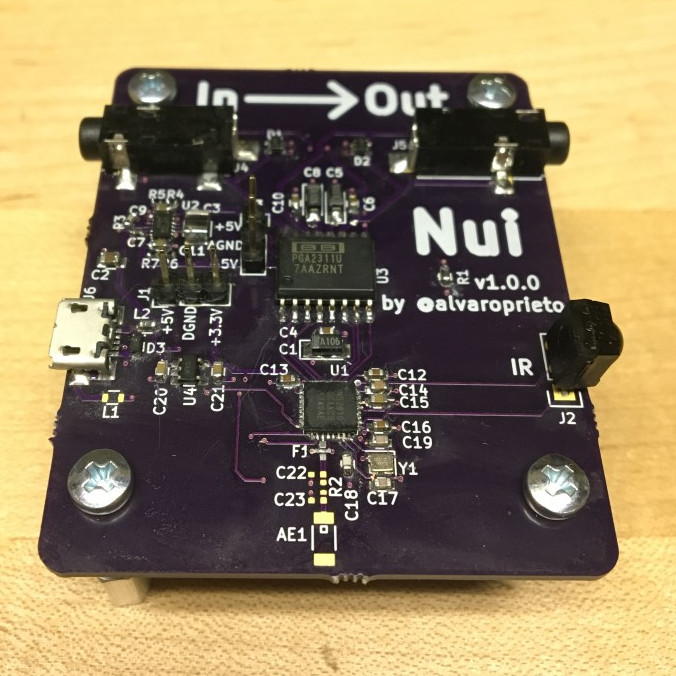
Alvaro Prieto made an IR volume controller and wrote a post on his blog detailing its assembly:
Nui is an IR controlled volume controller for analog audio. It sits between your audio source and speakers and can amplify or reduce the volume using IR commands (and eventually BLE).
Why do I need this?
It all started because I have my trusty Logitech Z-2300 speakers and subwoofer I purchased back around 2004/5. They still work great, but instead of being on my computer, they are used for my TV. Unfortunately, the TV’s line out doesn’t honor the TV’s volume and is always outputting at max volume. Sure, I can get up and change the volume on the speakers themselves, but wouldn’t it be more convenient to do it with the TV remote?!
That’s how the Nui project started. It sits between my TV and my speakers and now I don’t have to get up to change the volume 😀
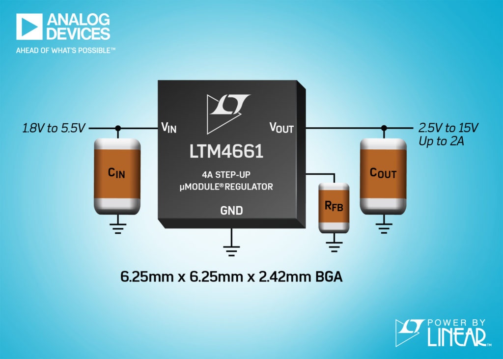
Analog Devices, Inc. has announced the Power by Linear LTM4661, a low power step-up µModule regulator in a 6.25mm x 6.25mm x 2.42mm BGA package. Only a few capacitors and one resistor are required to complete the design, and the solution occupies less than 1cm²single-sided or 0.5cm²on double-sided PCBs. The LTM4661 incorporates a switching DC/DC controller, MOSFETs, inductors and supporting components. The LTM4661 operates from a 1.8V to 5.5V input supply, and continues to operate down to 0.7V after start-up. The output voltage can be set by a single resistor ranging from 2.5V to 15V. The combination of the small, thin package and wide input and output voltage range is ideal for a wide range of applications including optical modules, battery-powered equipment, battery-based backup systems, bias voltage for power amps or laser diodes and small DC motors.
The LTM4661 can deliver 4A continuously under 3.3VINto 5VOUT, and 0.7A continuously under 3.3VINto 12VOUT. The LTM4661 employs synchronous rectification, which delivers as high as 92 per cent conversion efficiency (3.3VIN to 5VOUT). The switching frequency is 1MHz, and can also be synchronised to an external clock ranging from 500kHz to 1.5MHz. The LTM4661 1MHz switching frequency and dual phase single output architecture enable fast transient response to line and load changes and a significant reduction of output ripple voltage. The LTM4661 has three operation modes: Burst Mode operation, forced continuous mode and external sync mode. The quiescent current in Burst Mode operation is only 25µA, which provides extended battery run time. For applications demanding the lowest possible noise operation, the forced continuous mode or external sync mode minimise possible interference of switching noise.
The LTM4661 features an output disconnect during shutdown and inrush current limit at start-up. Fault protection features include short-circuit, overvoltage and over temperature protection. The LTM4661 operates from –40℃to 125℃operating temperature.
Hi guys, over the past few tutorials, we have been discussing TFT displays, how to connect and use them in Arduino projects, especially the 1.8″ Colored TFT display. In a similar way, we will look at how to use the 1.44″ TFT Display (ILI9163C) with the Arduino.
The ILI9163C based 1.44″ colored TFT Display, is a SPI protocol based display with a resolution of 128 x 128 pixels. It’s capable of displaying up to 262,000 different colors. The module can be said to be a sibling to the 1.8″ TFT display, except for the fact that it is much faster and has a better, overall cost to performance ratio when compared with the 1.8″ TFT display. Some of the features of the display are listed below;
Size: 1.44 inch
Interface: SPI
Resolution: 128*128 pixel
Visual area: 1:1 square
TFT color screen, the effect is far better than other small CSTN screen
Drive IC: ILI9163
Fully compatible and alternative 5110 interface
Onboard LDO, support 5V/3.3V input voltage, the LED backlight, 3.3V input
For this tutorial, we will focus on demonstrating how to use this display with Arduino to display texts, shapes and Images.
Using the 1.44″ Color TFT display (ILI9163C) with Arduino – [Link]
Hi guys, over the past few tutorials, we have been discussing TFT displays, how to connect and use them in Arduino projects, especially the 1.8″ Colored TFT display. In a similar way, we will look at how to use the 1.44″ TFT Display (ILI9163C) with the Arduino.
ILI9163C 1.44″ TFT Display
The ILI9163C based 1.44″ colored TFT Display, is a SPI protocol based display with a resolution of 128 x 128 pixels. It’s capable of displaying up to 262,000 different colors. The module can be said to be a sibling to the 1.8″ TFT display, except for the fact that it is much faster and has a better, overall cost to performance ratio when compared with the 1.8″ TFT display. Some of the features of the display are listed below;
Size: 1.44 inch
Interface: SPI
Resolution: 128*128 pixel
Visual area: 1:1 square
TFT color screen, the effect is far better than other small CSTN screen
Drive IC: ILI9163
Fully compatible and alternative 5110 interface
Onboard LDO, support 5V/3.3V input voltage, the LED backlight, 3.3V input
For this tutorial, we will focus on demonstrating how to use this display with Arduino to display texts, shapes and Images.
Required Components
The following components are required to replicate this tutorial.
Each of these components can be bought through the links attached to them.
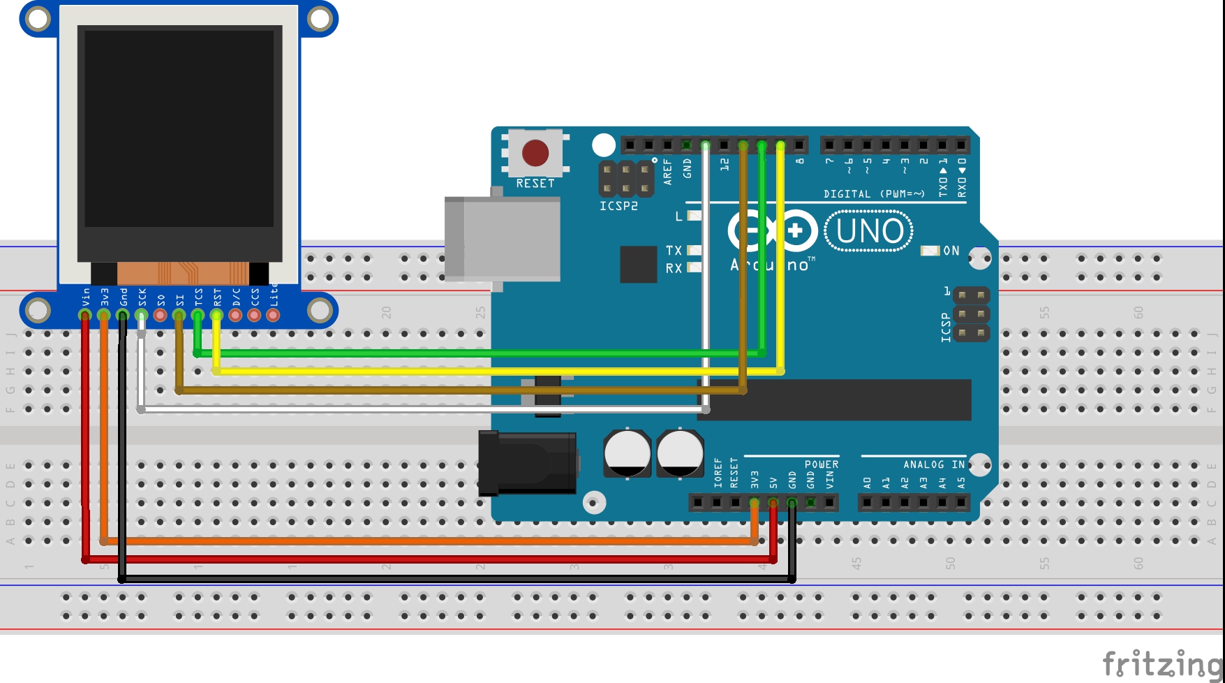
Schematics
TheTFT Display, as earlier stated, communicates with the microcontroller over SPI, thus to use it, we need to connect it to the SPI pins of the Arduino as shown in the schematics below.
Schematics
Please note that the version of the display used for this tutorial is not available on fritzing which is the software used for the schematics, so follow the pin connection list below to further understand how each pin of the TFT display should be connected to the Arduino.
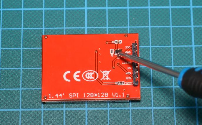
When connecting the display, ensure that has a voltage regulator (shown in the image below) before connecting it directly to the 5v logic level of the Arduino. This is because the display could be destroyed if the version of the display you have does not have the regulator.
If the display does not have a voltage regulator, you can use any logic level converter/shifter in between the display and the Arduino.
Check the connections once again to be sure everything is connected as it should be before proceeding to the next section.
Code
In order to allow the Arduino to work with the display, we need two Arduino libraries; the sumotoy TFT ILI9163C Arduino library which can be downloaded from this link and the popular Adafruit GFX Arduino library which we have used extensively in several tutorials. Download these libraries and install them in the Arduino IDE.
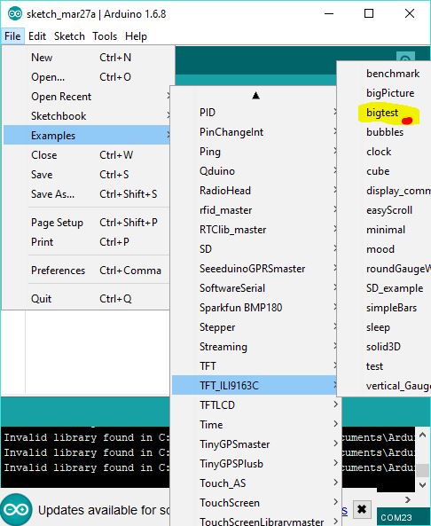
For today’s tutorial, we will be using the bigtest example which is one of the example codes that comes with the sumotoy ILI9163C Arduino library to show how to use the TFT display.
The example can be opened by going to File–>Examples–>TFT_ILI9163c–>bigtest as shown in the image below. It should be noted that this will only be available after the sumotoy library has been installed.
To explain the code, as usual, the first thing that was done is the inclusion of all the libraries needed for the code.
Next, we define some of the colors that will be used along with the corresponding hex values. If you’ve gone through any of our previous tutorials where we used the Adafruit GFX library, you would have noticed that this code contains a lot from the GFX library and it should be easier for you to follow.
// Color definitions
#define BLACK 0x0000
#define BLUE 0x001F
#define RED 0xF800
#define GREEN 0x07E0
#define CYAN 0x07FF
#define MAGENTA 0xF81F
#define YELLOW 0xFFE0
#define WHITE 0xFFFF
Next, the pins of the Arduino to which the CS and DC pin of the TFT display are connected is declared.
#define __CS 10
#define __DC 9
Next, an object of the ILI9163c library named “display” was created with CS and DC parameter as inputs but due to the kind of display being used, we need to include the pin of the Arduino to which the A0 pin of the TFT display is connected which is D8.
With this done, we move to the void setup() function. Under this function, we issue the commands that initialize the display then create a time variable updated by millis, after which we issue a command to clear the screen and display some random text on it.
void setup(void) {
display.begin();
uint16_t time = millis();
time = millis() - time;
// lcdTestPattern();
// delay(1000);
display.clearScreen();
display.setCursor(0,0);
display.print("Lorem ipsum dolor sit amet, consectetur adipiscing elit. Curabitur adipiscing ante sed nibh tincidunt feugiat. Maecenas enim massa");
delay(1000);
Some of the functions which perform actions ranging from displaying fastlines, drawing rectangles etc are then called with a delay after each function so the text or graphics stays long enough on the screen to be visible.
Up next is the void loop function. The void loop function also calls some of the same functions called under the void setup() function to display circles, rectangles etc including the testline function which is essentially used to test the screen.
The rest of the code is for the functions that were called and may not be too difficult to follow.
The complete code for this project is available below and under the example section of the Arduino IDE as described at the beginning of this section.
#include <SPI.h>
#include <Adafruit_GFX.h>
#include <TFT_ILI9163C.h>
// Color definitions
#define BLACK   0x0000
#define BLUE    0x001F
#define RED     0xF800
#define GREEN   0x07E0
#define CYAN    0x07FF
#define MAGENTA 0xF81F
#define YELLOW  0xFFE0
#define WHITE   0xFFFF
/*
Teensy3.x and Arduino's
You are using 4 wire SPI here, so:
MOSI: 11//Teensy3.x/Arduino UNO (for MEGA/DUE refere to arduino site)
MISO: 12//Teensy3.x/Arduino UNO (for MEGA/DUE refere to arduino site)
SCK: 13//Teensy3.x/Arduino UNO (for MEGA/DUE refere to arduino site)
the rest of pin below:
*/
#define __CS 10
#define __DC 9
/*
Teensy 3.x can use: 2,6,9,10,15,20,21,22,23
Arduino's 8 bit: any
DUE: check arduino site
If you do not use reset, tie it to +3V3
*/
float p = 3.1415926;
void setup(void) {
  display.begin();


  uint16_t time = millis();
  time = millis() - time;

//  lcdTestPattern();
//  delay(1000);

  display.clearScreen();
  display.setCursor(0,0);
  display.print("Lorem ipsum dolor sit amet, consectetur adipiscing elit. Curabitur adipiscing ante sed nibh tincidunt feugiat. Maecenas enim massa");
  delay(1000);
tftPrintTest();
  delay(2000);

  //a single pixel
  display.drawPixel(display.width()/2, display.height()/2, GREEN);
  delay(500);

  // line draw test
  testlines(YELLOW);
  delay(500);

  // optimized lines
  testfastlines(RED, BLUE);
  delay(500);

  testdrawrects(GREEN);
  delay(1000);

  testfillrects(BLUE, YELLOW);
  delay(1000);

  randomRect(0);
  delay(100);
  randomCircles(0);
  delay(100);
  randomLines();
  delay(100);
  randomPoints();
  delay(500);

  display.clearScreen();
  testfillcircles(10, BLUE);
  testdrawcircles(10, WHITE);
  delay(1000);

  testroundrects();
  delay(500);

  testtriangles();
  delay(500);
}
void loop() {
  testlines(random(0x0010,0xFFFF));
  randomLines();
  //randomCircles(1);
  randomCircles(0);
  randomRect(1);
  randomRect(1);
  randomRect(1);
  randomRect(1);
  randomRect(1);
  randomRect(0);
  randomRect(0);
  randomRect(0);
  randomRect(0);
  randomRect(0);
  randomRect(0);
  randomPoints();
}
void testlines(uint16_t color) {
display.clearScreen();
for (int16_t x=0; x < display.width()-1; x+=6) {
display.drawLine(0, 0, x, display.height()-1, color);
}
for (int16_t y=0; y < display.height()-1; y+=6) {
display.drawLine(0, 0, display.width()-1, y, color);
}
display.clearScreen();
for (int16_t x=0; x < display.width()-1; x+=6) {
display.drawLine(display.width()-1, 0, x, display.height()-1, color);
}
for (int16_t y=0; y < display.height()-1; y+=6) {
display.drawLine(display.width()-1, 0, 0, y, color);
}
display.clearScreen();
for (int16_t x=0; x < display.width()-1; x+=6) {
display.drawLine(0, display.height()-1, x, 0, color);
}
for (int16_t y=0; y < display.height()-1; y+=6) {
display.drawLine(0, display.height()-1, display.width()-1, y, color);
}
display.clearScreen();
for (int16_t x=0; x < display.width()-1; x+=6) {
display.drawLine(display.width()-1, display.height()-1, x, 0, color);
}
for (int16_t y=0; y < display.height()-1; y+=6) {
display.drawLine(display.width()-1, display.height()-1, 0, y, color);
}
delay(500);
}
void testdrawtext(char *text, uint16_t color) {
display.setTextSize(1);
display.setTextColor(WHITE);
display.setCursor(0,0);
for (uint8_t i=0; i < 168; i++) {
if (i == '\n') continue;
display.write(i);
if ((i > 0) && (i % 21 == 0))
display.println();
}
}
void testfastlines(uint16_t color1, uint16_t color2) {
display.clearScreen();
for (int16_t y=0; y < display.height()-1; y+=5) {
display.drawFastHLine(0, y, display.width()-1, color1);
}
for (int16_t x=0; x < display.width()-1; x+=5) {
display.drawFastVLine(x, 0, display.height()-1, color2);
}
}
void testdrawrects(uint16_t color) {
display.clearScreen();
for (int16_t x=0; x < display.height()-1; x+=6) {
display.drawRect((display.width()-1)/2 -x/2, (display.height()-1)/2 -x/2 , x, x, color);
}
}
void testfillrects(uint16_t color1, uint16_t color2) {
display.clearScreen();
for (int16_t x=display.height()-1; x > 6; x-=6) {
display.fillRect((display.width()-1)/2 -x/2, (display.height()-1)/2 -x/2 , x, x, color1);
display.drawRect((display.width()-1)/2 -x/2, (display.height()-1)/2 -x/2 , x, x, color2);
}
}
void testfillcircles(uint8_t radius, uint16_t color) {
for (uint8_t x=radius; x < display.width()-1; x+=radius*2) {
for (uint8_t y=radius; y < display.height()-1; y+=radius*2) {
display.fillCircle(x, y, radius, color);
}
}
}
void testdrawcircles(uint8_t radius, uint16_t color) {
for (int16_t x=0; x < (display.width()-1)+radius; x+=radius*2) {
for (int16_t y=0; y < (display.height())-1+radius; y+=radius*2) {
display.drawCircle(x, y, radius, color);
}
}
}
void testtriangles() {
display.clearScreen();
int color = 0xF800;
int t;
int w = display.width()/2;
int x = display.height();
int y = 0;
int z = display.width();
for(t = 0 ; t <= 15; t+=1) {
display.drawTriangle(w, y, y, x, z, x, color);
x-=4;
y+=4;
z-=4;
color+=100;
}
}
void testroundrects() {
display.clearScreen();
int color = 100;
int i;
int t;
for(t = 0 ; t <= 4; t+=1) {
int x = 0;
int y = 0;
int w = display.width();
int h = display.height();
for(i = 0 ; i <= 24; i+=1) {
display.drawRoundRect(x, y, w, h, 5, color);
x+=2;
y+=3;
w-=4;
h-=6;
color+=1100;
}
color+=100;
}
}
void tftPrintTest() {
display.clearScreen();
display.setCursor(0, 5);
display.setTextColor(RED);
display.setTextSize(1);
display.println("Hello World!");
display.setTextColor(YELLOW, GREEN);
display.setTextSize(2);
display.print("Hello Wo");
display.setTextColor(BLUE);
display.setTextSize(3);
display.print(12.57);
delay(1500);
display.setCursor(0, 5);
display.clearScreen();
display.setTextColor(WHITE);
display.setTextSize(0);
display.println("Hello World!");
display.setTextSize(1);
display.setTextColor(GREEN);
display.print(p, 5);
display.println(" Want pi?");
display.print(8675309, HEX);
display.print(" Print HEX");
display.setTextColor(WHITE);
display.println("Sketch has been");
display.println("running for: ");
display.setTextColor(MAGENTA);
display.print(millis() / 1000);
display.setTextColor(WHITE);
display.print(" sec.");
}
void randomRect(bool fill){
display.clearScreen();
uint8_t k,c;
for (k = 0; k < 16; k++) {
for (c = 0; c < 32; c++) {
uint8_t cx, cy, x, y, w, h;
// center
cx = random(0,display.width());
cy = random(0,display.height());
// size
w = random(0,30 + 6);
h = random(0,20 + 4);
// upper-left
x = cx - w / 2;
y = cy - h / 2;
if (x < 0) x = 0;
if (y < 0) y = 0;
// adjust size
if (x + w > display.width()) w = display.width() - x;
if (y + h > display.height()) h = display.height() - y;
if (fill){
display.fillRect(x, y, w, h,random(0x0010,0xFFFF));
}
else {
display.drawRect(x, y, w, h,random(0x0010,0xFFFF));
}
}
display.clearScreen();
}
}
void randomCircles(bool fill){
display.clearScreen();
uint8_t k,c;
for (k = 0; k < display.height(); k++) {
for (c = 0; c < display.height()/2; c++) {
// coordinates
uint8_t x = random(0,120 + 3), y = random(0,90 + 2), r = random(0,40 + 1);
if (x - r < 0) r = x;
if (x + r > (display.width()-1)) r = (display.width() - 1) - x;
if (y - r < 0) r = y;
if (y + r > (display.height()-1)) r = (display.height() - 1) - y;
if (fill){
display.fillCircle(x, y, r,random(0x0010,0xFFFF));
}
else {
display.drawCircle(x, y, r,random(0x0010,0xFFFF));
}
}
if (!fill)display.clearScreen();
}
}
void randomLines(){
display.clearScreen();
uint8_t k,c;
for (k = 0; k < display.height(); k++) {
for (c = 0; c < display.height()/2; c++) {
uint8_t x1 = random(0,display.width()), y1 = random(0,display.height()), x2 = random(0,display.width()), y2 = random(0,display.height());
display.drawLine(x1, y1, x2, y2,random(0x0010,0xFFFF));
}
display.clearScreen();
}
}
void randomPoints(){
display.clearScreen();
int k,c;
for (k = 0; k < 128; k++) {
for (c = 0; c < 1000; c++) {
uint8_t x = random(0,display.width()), y = random(0,display.height());
display.drawPixel(x, y,random(0x0010,0xFFFF));
}
display.clearScreen();
}
}
Demo
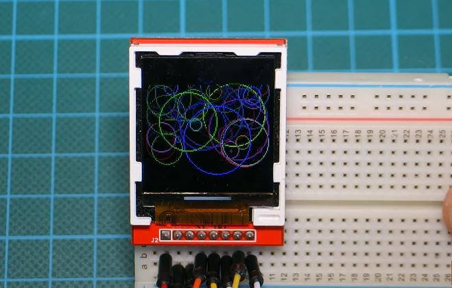
With the libraries installed, open an instance of the Arduino IDE, open the examples as described initially, don’t forget to make the A0 pin (D8) correction to the code then upload to the Arduino board. You should see different kind of text and graphics being displayed on the screen. I captured the screen in action and its shown in the image below.
Demo
Awesome, yes?
That’s it for this tutorial guys, what interesting thing are you going to build with this display? Let’s get the conversation started. Feel free to reach me via the comment section if you have any questions about the tutorial.
Till next time!
You can watch the video of this tutorial on youtube here
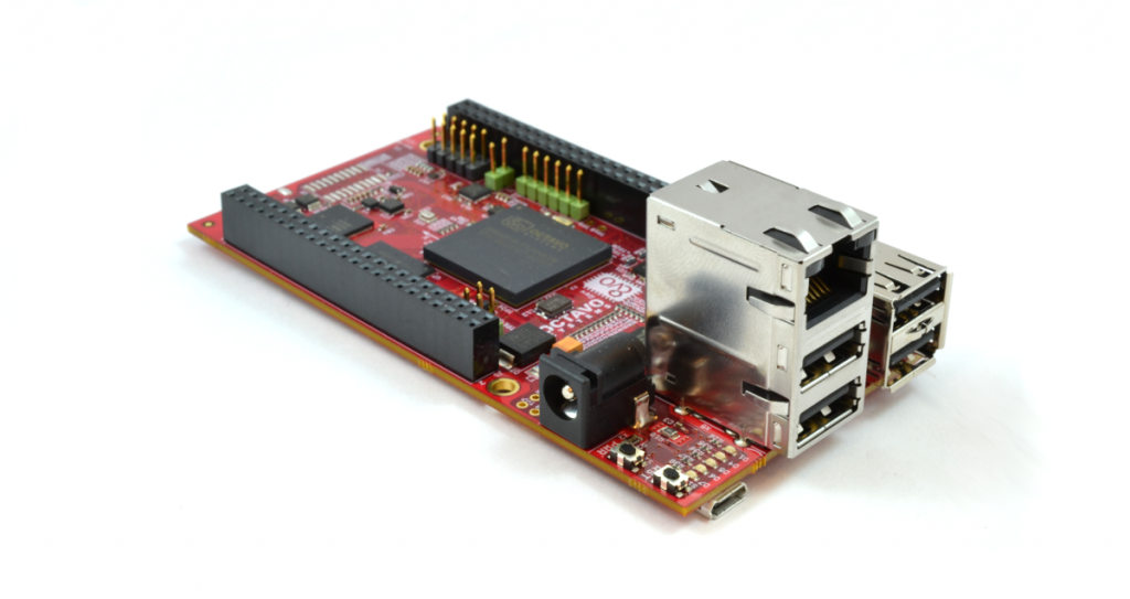
The OSD3358-SM-RED from Octavo Systems is a reference, evaluation, and development board for the OSD335x-SM series of System-in-Package (SiP) devices. It is powered by a 1 GHz processor, ADC, and 1 GB of DDR2 RAM into an enclosure of the size of a coin.
OSD3358-SM-RED single-board computer
The SiP needs a PCB, along with components like an Ethernet jack, power supply, IO pins, and USB sockets to communicate with the other complimentary electronic parts. These boards include several power options, including a micro-USB connector, barrel jack, and solder points for battery usage. Ethernet and USB connectors are included, along with expansion connectors setup so that BeagleBone Black Capes can be connected directly. Finally, a 9-axis IMU, barometer, and temperature sensor are included. Data from sensors can be collected directly without the help of extra hardware or software.
This board is longer and slightly wider than a Raspberry Pi, at an exact dimension of 108 x 54 mm. It’s also thicker at 32 mm due to the decision to mount the Ethernet jack on top of the two USB ports. A micro-SD card slot is included, though WiFi capability is not provided. For internet connectivity, the user needs to rely on wired or dongle connection.
It comes pre-loaded with a Debian Linux distribution, complete with drivers for the onboard sensors already available. It can also boot off of the SD card to load other Operating Systems. This board can be used in one of three ways: as a standalone device, a USB client, or using a UART port as a Linux terminal. In the standalone case, the user simply connects the micro-USB connector to an appropriate power source, then to a monitor via a micro-HDMI to HDMI adapter. Once booted up, the screen goes to a minimal Linux install, allowing the user to access a web browser, terminal, and other necessary tools that a developer can build upon.
At a cost of $199, this board wouldn’t be an appropriate substitute for a Raspberry Pi or BeagleBone in standalone situations, but it will certainly be useful for a professional upgrade to OSD335x-SM SiPs.
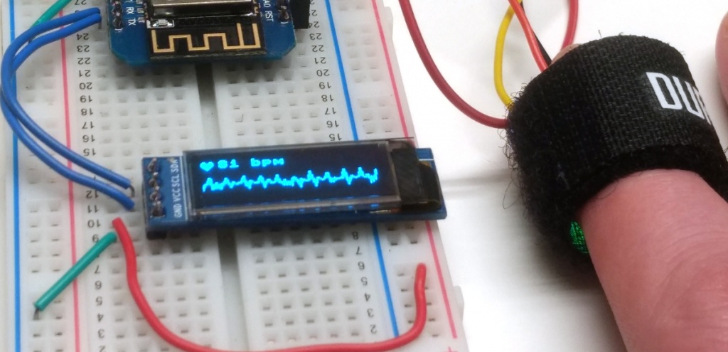
By Martin Fitzpatrick @ martinfitzpatrick.name show us how to build the micro display heart-rate monitor.
Pulse sensors have become popular due to their use in health-monitors like the Fitbit. The sensors used are cheap, simple and pretty reliable at getting a reasonable indication of heart rate in daily use. They work by sensing the change in light absorption or reflection by blood as it pulses through your arteries — a technique jauntily named photoplethysmography (PPG). The rising and falling light signal can be used to identify the pulse, and subsequently calculate heart rate.
Heart-rate monitor on a small OLED display with MicroPython – [Link]
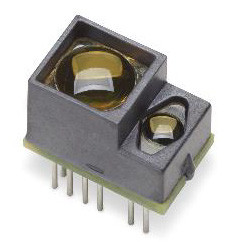
The AFBR – S50 is a multipixel distance and motion measurement sensor. It has an integrated 850nm vertical cavity surface emitting laser (VCSEL) which uses a single voltage supply of 5V. It’s measurement rates are quick and as fast as 3 kHz, which is a distinguishing feature. However, this is not the reason why the AFBR – S50 stands out. It is different because unlike other Time of Flight (ToF) ranging sensors, the AFBR – S50 can measure up to 10 meters whereas similar sensors don’t get close to that.
The AFBR-S50
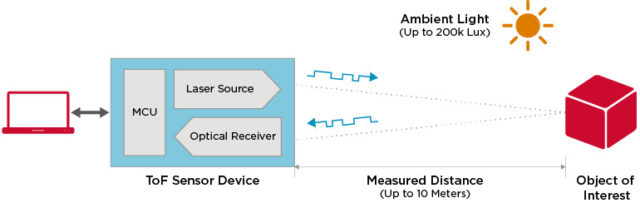
Furthermore, the sensor works on the principle of Optical Time of Flight. Time-of-Flight principle (ToF) is a method for measuring the distance between a sensor and an object, based on the time difference between the emission of a signal and its return to the sensor, after being reflected by an object. If you have used the popular HC-SR05 Ultrasonic sensor, then you have seen this principle in action. The AFBR – S50 can be used both inside and outside to cover wide ranges of ambient light. It supports almost 3000 frames every second with an accuracy of less than one percent on diverse types of surfaces.
ToF Principle
The multi-pixel sensor works with up to 16 illuminated pixels out of 32 and with its best-in-class ambient light suppression of up to 200kLx, to ensure smooth usage outside. It uses SPI Interface to communicate with a host device. AFBR – S50 not only works outside but it is also equally effective on colored, white, black and metallic reflection objects.
Broadcom has released two different versions of the sensor:
AFBR-S50MV680B
680nm laser light source.
One illuminated pixel
FOV (Field Of View) 1.55° x 1.55°
Single voltage – 5V supply
AFBR-S50MV85G
850nm laser light source
9-16 illuminated pixels
FOV 6.2° x 6.2°
Single voltage – 5V supply
Below are the General Specifications for the Multipixel sensor:
Integrated 850nm laser light source.
Between 9-16 illuminated pixels.
FOV 6.2°x 6.2° (1.55 x 1.55°/pixel).
High-speed measurement rates of up to 3 kHz.
Variable distance range up to 10m.
Operation up to 200k Lux ambient light.
Works well on all surface conditions.
SPI digital interface (up to 20 MHz).
Single voltage supply 5V.
Integrated clock source.
Laser Class 1.
Accuracy < 1 percent.
Drop-in compatible with the AFBR-S50 sensor platform
Applications for the ToF sensor can be found in areas of industrial sensing, gesture sensing, distance measurement, robotics, drones, automation, and control. The AFBR-S50 is available, but the price is currently undisclosed. You can contact Broadcom sales for more information. More details can be found on the product page, and the AFBR-S50 datasheet can be found here.
If you are new into hardware or still familiarizing yourself to the hardware ecosystem, you will realize some common terms often appear which could sometimes sound confusing or something out of rocket science, but it’s not. Here’s a quick look at five common terms used in hardware products or boards and what they denote.
Let’s take a look at them –
System-in-a-Package (SiP)
Cross section of a SiP
A system in package (SiP) contains several ICs (chips) including a microprocessor on a single substrate such as ceramic or laminate. An example SiP can comprise several chips—such as a specialized processor, DRAM, flash memory—combined with passive components—resistors and capacitors—all mounted on the same substrate. This means that a complete functional unit can be built in a multi-chip package so that few external components need to be added to make it work.
SiP dies can be stacked vertically or tiled horizontally, unlike slightly less dense multi-chip modules, which place dies horizontally on a carrier. SiP connects the dies with standard off-chip wire bonds or solder bumps.
The appeal of a SiP is that it can be compact an otherwise complex system into a very simple package, making it easier to integrate into larger systems. It also simplifies PCB layouts.
Unlike a SOC that is based on a single silicon die, SiP can be based on multiple dies in a single package. SiP is believed to provide more interconnection in the future and possibly face out SoCs.
Package-on-a-Package (PoP)
Package on a Package
A Package-on-a-Package stacks single-component packages vertically, connected via ball grid arrays. Packages can be discrete components (memory, CPU, other logic) or a System-in-a-Package stacked with another package for added or expanded functionality.
PoP provides more component density and also simplifies PCB design. It can also improve signal propagation since the interconnects between components is much shorter.
System-on-a-Chip (SoC)
A System-on-a-chip (SoC) is a microchip with all the necessary electronic circuits and parts for a given system, such as a smartphone or wearable computer, into a single integrated circuit (IC).
An SoC integrates a microcontroller (or microprocessor) with advanced peripherals like graphic processing unit (GPU), Wi-Fi module, or coprocessor.
Think of an SoC as a computer package inside a chip. The SoC integrates all components of a system into one. It may contain digital, analog, mixed-signal, and often radio-frequency functions – all on a single substrate. An SoC can be based around either a microcontroller (includes CPU, RAM, ROM, and other peripherals) or a microprocessor (includes only a CPU). It is also possible for SoCs to be customized for a specific application, including whatever components, memory, or peripherals necessary, ranging from digital/analog signal ICs, FPGAs, and IOs.
One of the major advantages of an SoC is that it is usually cheaper, smaller, easy to scale, and even more energy efficient. It is easier to build around a SoC for a product than to add several components individually. Despite its obvious advantages, SoC still has a significant disadvantage – you are going to be locked into that hardware configuration for life. This could be fine for consumer products, since you don’t expect any hardware upgrade or so but would limit hacking for makers related application.
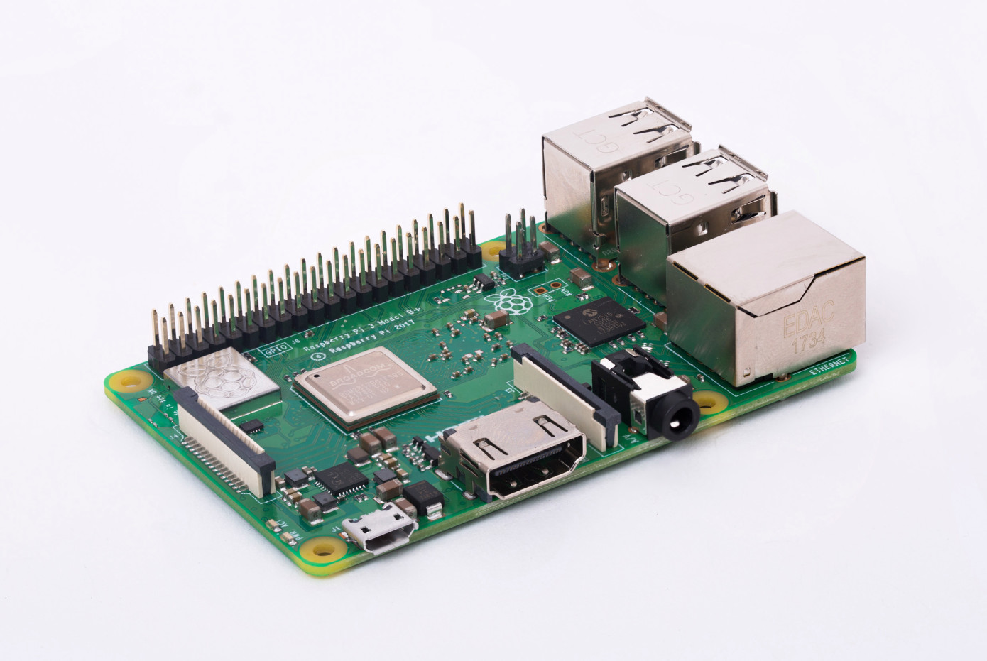
A good example of an SoC is what we have in the Raspberry Pi; The Raspberry Pi uses a system on a chip as an almost fully-contained microcomputer. SoCs can help engineers speed up a product to market and even the adoption of new protocols, such as those Bluetooth 5 SoCs, that make it easier to integrate Bluetooth 5 into new products.
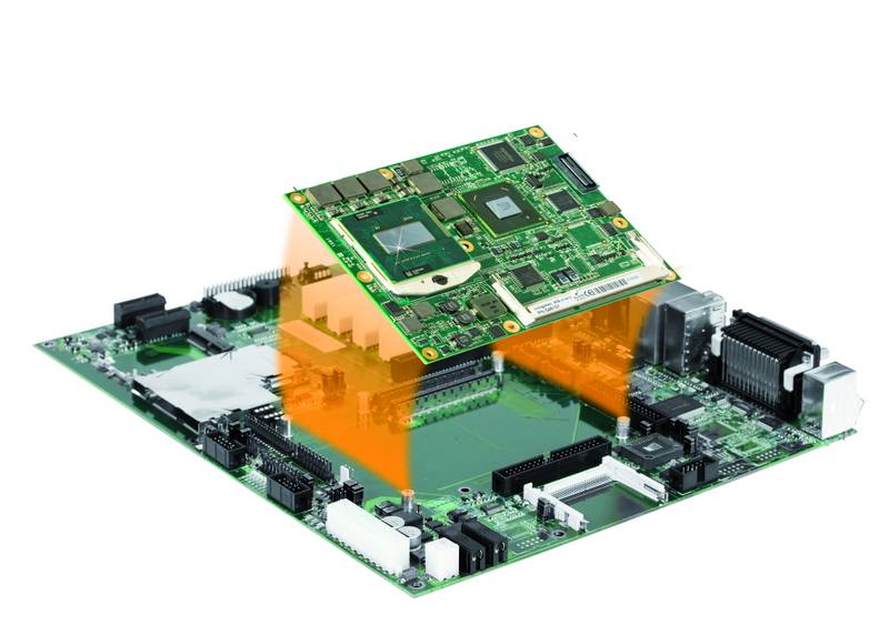
System on Module (SoM) / Computer on Module (CoM)
Computer on a module
A System on a Module (SoM) and Computer on Module usually refers to the same thing. A Computer-on-a-module is a step above an SoC. It means a computer or system packaged in a single module. CoMs usually provide every piece you need to build a complete system; they incorporate an SoC (most of the time), connectivity, multimedia and display, GPIO, operating system, and others into one single module.
SoM based designs are usually scalable. SoMs/CoMs are usually paired with a carrier board. These carrier boards are usually used to extend out the SoMs functionality or parts. A SoM helps system designers realize a fully customized electronics assembly, complete with custom interfaces and form factor without the effort of a ground-up electronics design. Customers can purchase an off-the-shelf SoM and marry it to an easy to develop custom baseboard to create a solution functionally identical to one that is fully custom-engineered.
CoMs provide a plug-and-play type advantage since a CoM can be replaced or upgraded within a carrier, without having to change the carrier. There are some benefits to the SoM approach vs. ground-up development. These include cost savings, reduced risk, a variety of CPU choices, decreased customer design requirements, and a small footprint.
Unlike an SBC, a computer-on-module is a type of single-board computer made to plug into a carrier board, baseboard, or backplane for system expansion.
Single Board Computers (SBCs)
A Raspberry Pi SBC
A single-board computer (SBC) is a complete computer built on a single circuit board, with a microprocessor(s), memory, input/output (I/O) and other features required for a functional computer. Single-board computers were made as demonstration or development systems, for educational systems, or for use as embedded computer controllers.
Single-board computer builds on SoC to provide a full-fledged computer on small circuit board. Examples of popular SBCs are Raspberry Pi boards, Nvidia Jetson, Beaglebone, and several others.
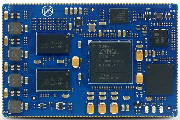
MYIR Tech has launched an $85 module, Xilinx Zynq-7010 or -7007S that runs on MYC-C7Z010/007S CPU Module. MYC-C7Z010/007S CPU Module is a part of their newly launched sandwich-style, $209 MYD-Y7Z010/007S Development Board. There’s an open source Linux 3.15.0 based BSP for the module, and the MYD-Y7Z010/007S carrier board ships with schematics. Both the module and development board can withstand -40 to 85°C temperature range.
MYC-C7Z010/007S CPU Module
MYC-C7Z010/007S CPU Module
Xilinx’s Zynq-7010 has dual-coreArm Cortex-A9 block as the Zynq-7015 or Zynq-7020, which is available along with the Z010 on the earlier MYC-C7Z010/20 module. However, the Zynq-7010 SoC has more FPGA logic cells (28K). On the other hand, the Zynq-7007S is limited to a single Cortex-A9 core and a 23K logic cell FPGA. The Zynq-7010 ranges from 667MHz to 866MHz while the 7007S can operate from 667MHz to 766MHz.
The MYC-C7Z010/007S has 75 x 50mm dimension. It ships with 512MB DDR3 SDRAM, 4GB eMMC, and 16MB quad SPI flash. There’s a Gigabit Ethernet PHY and external watchdog. A 1.27mm 180-pin stamp-hole (Castellated-Hole) expansion interface is also there for ARM and FPGA interfaces that are useful to improve shock resistance. Supported I/O incorporates single USB and SDIO interfaces plus a pair of serial, I2C, CAN, SPI, and 16-channel ADC.
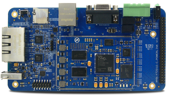
MYD-Y7Z010/007S dev board
MYD-Y7Z010/007S Dev Board
The 153 x 80mm MYD-Y7Z010/007S Development Board expands the MYC-C7Z010/007S CPU module with 3x GbE ports, a USB 2.0 OTG port and a DB9 combo port with isolated RS232, RS485, and CAN signals. There’s also a microSD slot for memory expansion and a debug serial port.
An optional, $29 MYD-Y7Z010/007S I/O Cape plugs into the GPIO interface offering an HDMI port, a user button, and LCD, camera, and dual Pmod connectors. The LCD interface supports optional MYIR 7- or 4-inch capacitive and resistive LCD modules. The HDMI port only supports 720p resolution for now. The MYD-Y7Z010/007S board is further equipped with a reset key and boot switch. There’s also a 12V/2A DC input.
The MYC-C7Z010/007S module with the Zynq-7010 is available now for $85. The MYD-Y7Z010/007S Development Board is available with the Zynq-7010 based module for $209. More information is available at MYIR’s MYC-C7Z010/007S and MYD-Y7Z010/007S product pages.
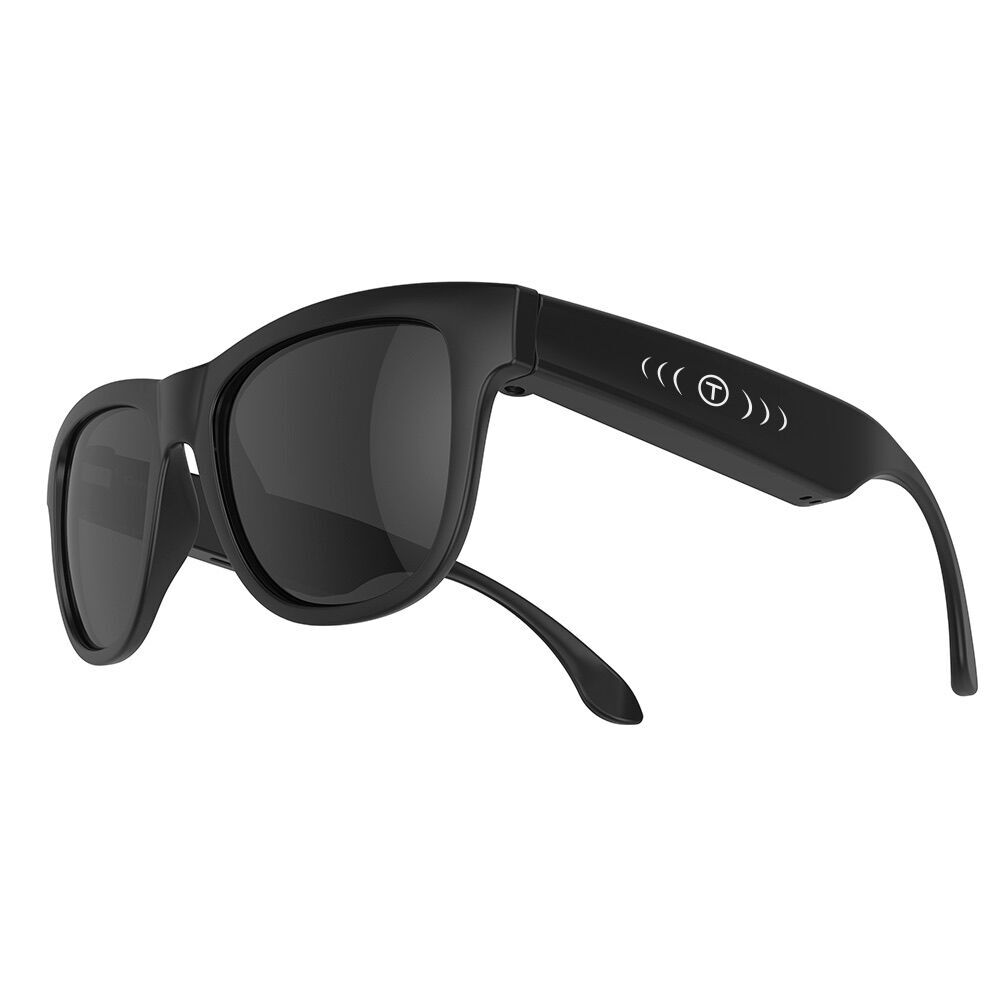
In the last few years, we have seen an increasing interest in smart glasses. Some analysts believe that in the next few years, smart glasses will be at the center of consumer and business electronics in the same way that smartphones are today. Companies and Startups like Google, Intel, Vue, Vuzix, and many others have all come up with their smart glass initiative, and even Apple has many smart-glasses patents with possibly over hundreds of engineers working on that field. One of the challenges that come with smart glasses is that they usually don’t always look socially acceptable, and most are always geeky like. Voxos is hoping to change that, by building a smart glass that looks like every-day regular glass.
Voxos Smart Glass
Voxos on the surface looks like your typical eyeglasses, but there is more to it. Voxos is a smart glass that allows to listen to music without actually plugging in an earphone or headset. The smartness in Voxos comes from its built-in bone conduction technology. Bone conduction uses the natural vibrations of a person’s bones — such as skull, jaw, and cheekbones — to hear a sound. So, the bone conduction technology works by vibrating sound through your skull opposed to straight into your ear like standard earphones. This means you can hear your environment while listening to Music, Podcasts, Map Navigation, Audio Assistant, Google Maps, Audiobooks, Fitness Apps and more at all times without being disconnected from their surroundings.
Friedrich Nietzsche once said, “Without music, life would be a mistake.” Technological advances in mobile technology and improved data streaming have increased access to on-demand streaming music. The number of paying subscribers has highly increased in the last five years. Music lovers are gearing up for better musical experience going for high-quality headphones, noise-canceling headphones, and earplugs. These accessories are becoming more common while offering an all-encompassing musical experience but this might be coming at an extreme price—and that price just might cost one their life. Studies have shown that a number of accidents involving pedestrians wearing headphones are on the rise. Aside from potential accidents that could be caused by putting on an earphone, another concern is ear-infection causing germs from sharing ear-phones or from not changing the headphone sponges. Voxos, on the other hand, has less of these concerns. Voxos takes bone conduction to the next level and creates the safe and convenient alternative to ear plugin headsets, especially for outdoor activities.
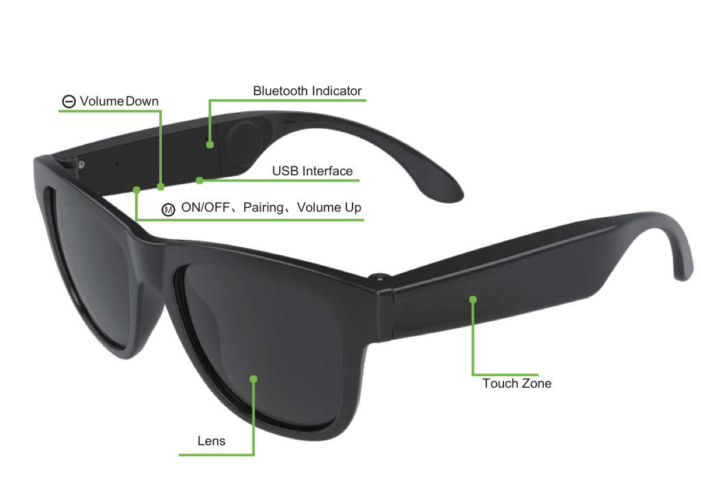
Voxos Smart Glass Parts
Voxos are designed to be worn during extensively long periods, and they can last a whopping 10 hours of active playing. Voxos connects to your smartphone via Bluetooth and works with most apps. Voxos is integrated with a touchpad on the right side and will allow the user to interact with the main function of the phone by just swiping or tapping the glass. It also comes with a USB interface for charging the inbuilt battery and two buttons for parring mode, volume up, and volume down activity.
With it’s generic and sporty look Voxos fits with every outfit and it’s waterproof. The perfect fit makes wearing it not only fashionable but also convenient. Voxos is indeed great for drivers, but it is also perfect for others, such as cyclists, pedestrians and anybody on the road!
Even though the bone conducting technology in Voxos is already existing in some other smart glasses, we expect in the near future that Smart glasses will improve to the point of becoming mainstream in both everyday life and in the enterprise. And the direction for smart glasses is already being set in leading-edge smartphones like Apple’s iPhone X.
Voxos smart glasses are currently not available, but you can sign up on the company’s website to know when it will be available and even get a 40% off your purchase. Voxos is expected to launch an Indiegogo campaign very soon and possibly a Kickstarter one as well.
UPDATE 07/05/2018: They just launched an exclusive pre-campaign on Indiegogo where they have a special discount only for a few days.