Axiomtek, a Taiwan based company has introduced new Pico-ITX form factor SBCs using Intel’s Apollo Lake processor. This line of SBCs from Axiomtek started with PICO312 with minimal coastline ports, and then followed with a COM-like PICO313. Recently they launched a similar 100 x 72mm PICO316 SBC with more versatile ports than the original PICO312.
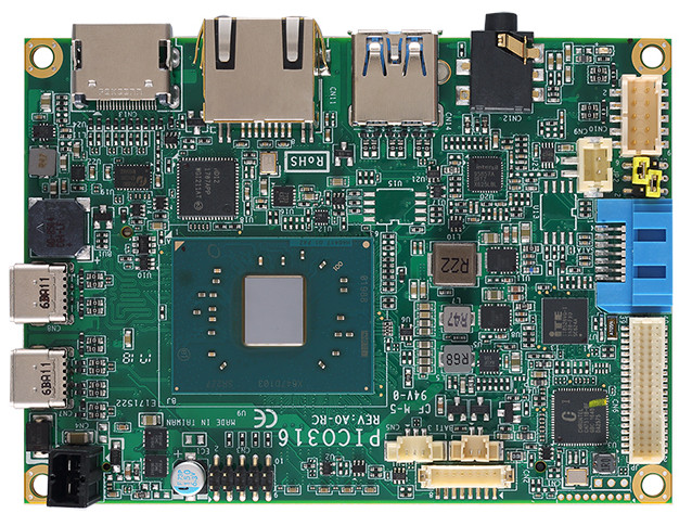
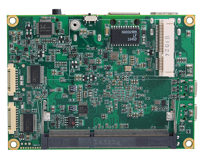
PICO316 SBC front sidePICO316 SBC backside
This PICO316 SBC is powered by Intel Pentium N4200 or Intel CeleronN3350 with Intel Gen9 Graphics. It supports up to 8GB DDR3L-1867 RAM. The SBC is compatible with most popular Linux kernels, such as Redhat, Fedora, Ubuntu also runs Windows as well. The IoT focused board also supports Axiomtek’s exclusive device monitoring and remote management software, AXView 2.0.
While the PICO312 and PICO313 were restricted to a single USB 2.0 interface, the PICO316 upgrades to pack three USB 3.0 ports, two of which are Type-C ports. Like the PICO312, the PICO316 has an HDMI port to enhance the LVDS interface. As an extra feature PICO316 provides dual RS-232 interfaces. On the other hand, the new PICO316 loses the previously available DIO and half-size mini-PCIe interfaces found on the PICO313, as well as the pair of general expansion connectors found on both of the earlier models.
The PICO316 is further provided with a SATA III interface, a GbE port, a full-size mini-PCIe slot with mSATA, an audio out jack, I2C, SMBus, and a watchdog. It runs on 5V, and it adds a -20°C to 70°C option in addition to the standard -20°C to 60°C.
Key Specifications for Axiomtek PICO316:
Processor: Intel Pentium N4200 or Intel Celeron N3350 (2.5GHz or 2.4GHz burst)
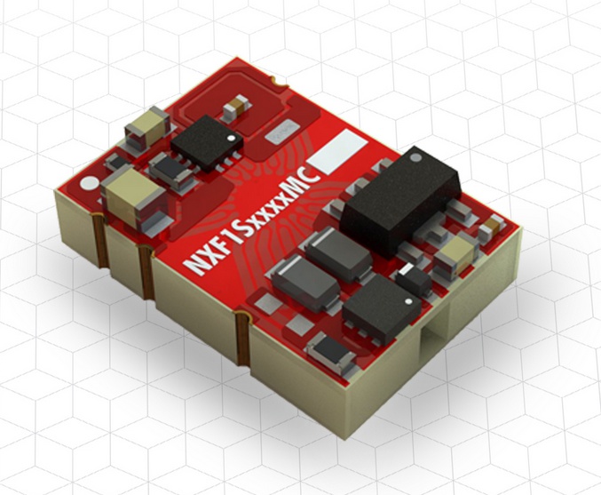
Expanding its range of embedded-core DC/DC converters, Murata Power Solutions adds the NXF1 series of regulated, high isolation converter with 3.3 or 5.0V outputs. Inputs available are nominal 3.3 and 5.0V in an industry-standard, surface-mount package with a low profile of 5.1mm. Line regulation is typically better than 0.03 per cent and load regulation is typically better than 0.5 per cent. All parts have continuous short circuit protection with auto re-start or latch-off depending on model and temperature. Input range is ± five per cent around the nominals of 3.3 and 5.0V.
Parts are 100 per cent production tested to 3.0kV DC and have agency recognition pending for ‘basic’ protection at 250V rms and ‘reinforced’ protection at 125V rms to UL60950. Medical recognition to ANSI/AAMI ES 60601-1 is also pending for two MOOPs (means of operator protection) and one MOPP (means of patient protection) at 125V rms and one MOOP based upon a working voltage of 250V rms max, between primary and secondary.
Typical applications are in systems where agency-recognised isolation is required with tight output regulation as is needed in power for remote pressure, hall-effect, mass airflow and other sensors. Markets addressed include alternative energy/solar power, transportation, telecomms/wireless equipment and medical.
The NXF1 series is rated at -40 to +105 degrees C with derating depending on model.
Packaging is the industry-standard footprint for SMT 1W converters in the Murata proprietary iLGA inspectable format with gold plated terminations. Parts are compatible with Pb-free soldering and backwards-compatible with Sn/Pb systems. They can be mounted in accordance with J-STD-020 with a classification temperature of 260 degrees C and Moisture Sensitivity Level (MSL) 2.
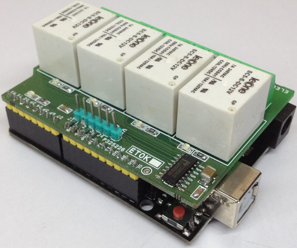
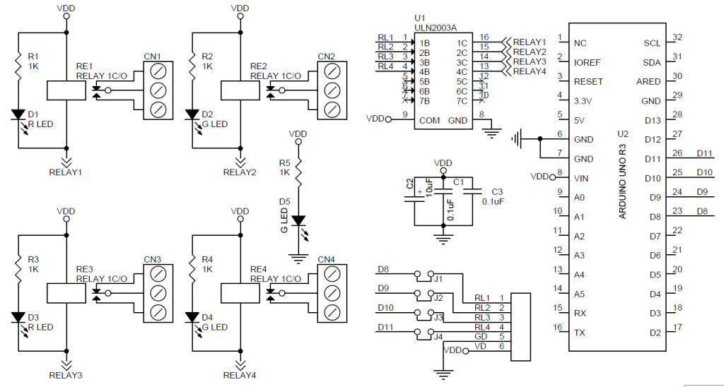
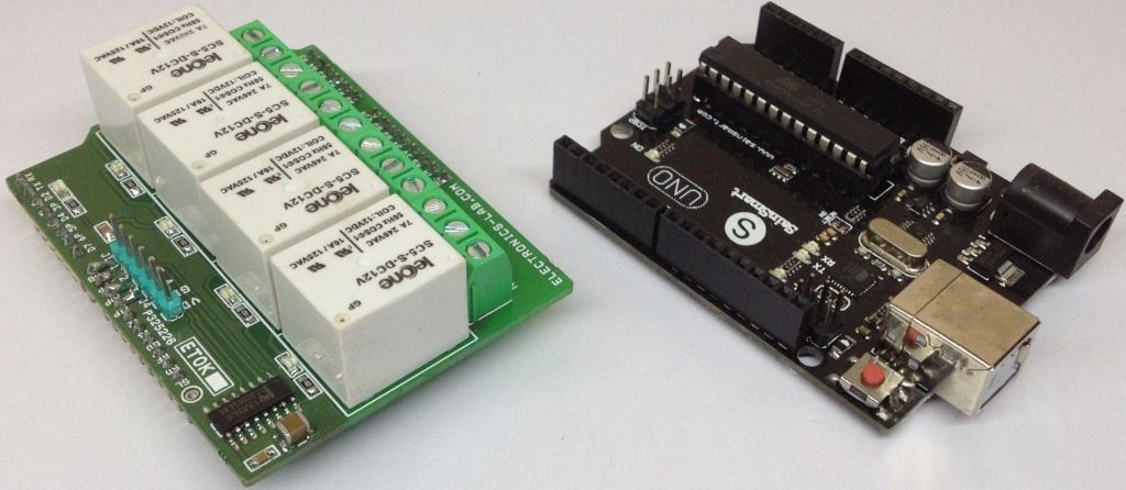
4 Channel Relay Shield for Arduino UNO is a simple and convenient way to interface 4 relays for switching applications in your project. Very compact design that can fit on top of Arduino UNO. Project requires 12V DC supply, all 4 trigger inputs require TTL signal, Relay-1 to Relay-4 inputs connected to D8 To D11 of Arduino digital pins through solder jumpers J1 To J4. All trigger inputs can be connected to other I/O pins of Arduino using female header connectors and you will need to open solder jumpers J1-J4 in this case. D1, D2, D3, D4 LEDs provided to indicate the Relay ON/OFF status. D5 is Power LED. Each relay has 3 pin screw terminals with normally open/normally closed switch to connect the load. Project is ideally used for low voltage applications and requires extra care in case of using high voltage AC switching.
Features
Input supply 12 VDC @ 170 mA ( Arduino DC Jack)
Output four SPDT relay
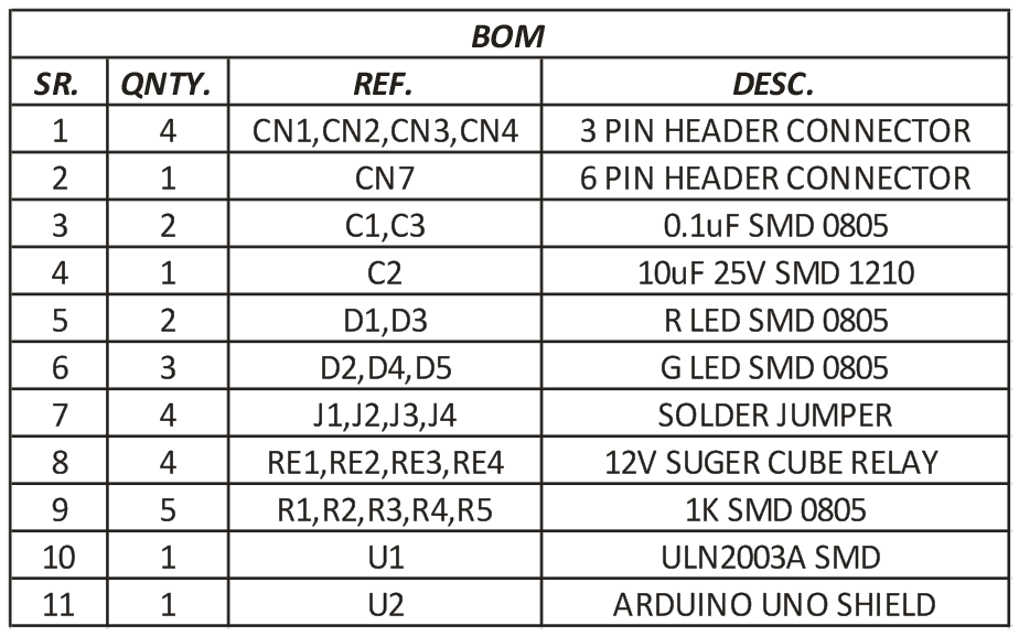
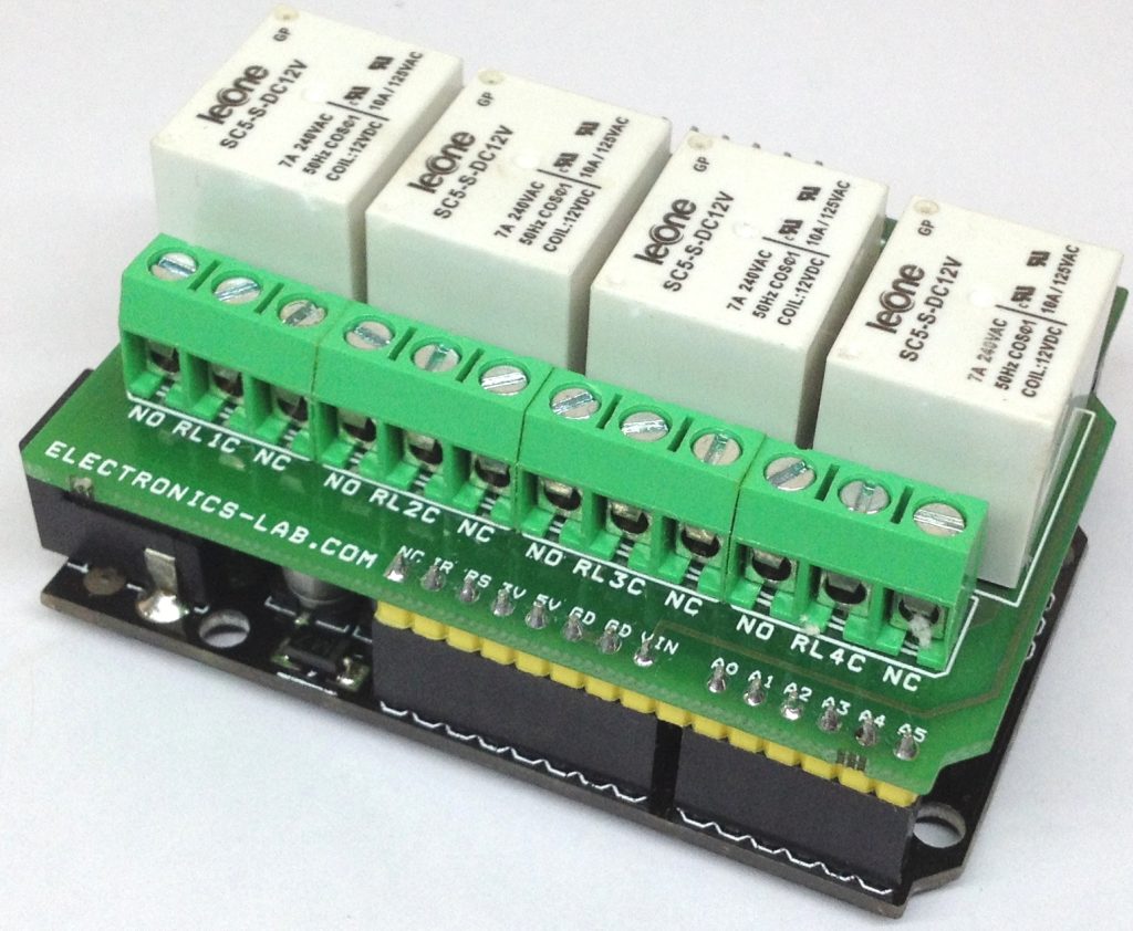
Relay specification 7A/24V DC-230V AC
Trigger level 2 ~ 5 VDC
Header Connector for connecting power and trigger voltage
4 Channel Relay Shield for Arduino UNO is a simple and convenient way to interface 4 relays for switching applications in your project. Very compact design that can fit on top of Arduino UNO. Project requires 12V DC supply, all 4 trigger inputs require TTL signal, Relay-1 to Relay-4 inputs connected to D8 To D11 of Arduino digital pins through solder jumpers J1 To J4. All trigger inputs can be connected to other I/O pins of Arduino using female header connectors and you will need to open solder jumpers J1-J4 in this case. D1, D2, D3, D4 LEDs provided to indicate the Relay ON/OFF status. D5 is Power LED. Each relay has 3 pin screw terminals with normally open/normally closed switch to connect the load. Project is ideally used for low voltage applications and requires extra care in case of using high voltage AC switching.
Features
Input supply 12 VDC @ 170 mA ( Arduino DC Jack)
Output four SPDT relay
Relay specification 7A/24V DC-230V AC
Trigger level 2 ~ 5 VDC
Header Connector for connecting power and trigger voltage
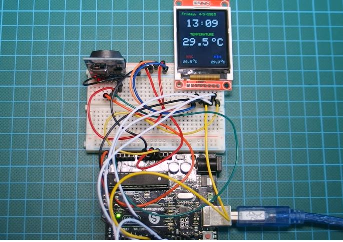
Hi guys, in one of our previous tutorials, we built a real-time clock with temperature monitor using the DS3231 and the 16×2 LCD display shield. Today, we will build an upgrade to that project by replacing the 16×2 LCD display with an ST7735 based 1.8″ colored TFT display.
Apart from changing the display, we will also upgrade the features of the project by displaying the highest and lowest temperature that has been measured over time. This feature could be useful in scenarios where there is a need to measure the maximum and minimum temperature experienced in a place over a particular time range.
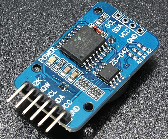
This tutorial is based on the ability and features of the DS3231 RTC module. The DS3231 is a low power RTC chip, it has the ability to keep time with incredible accuracy such that even after power has been disconnected from your project, it can still run for years on a connected coin cell battery. Asides from its ability to accurately keep time, this module also comes with an accurate temperature sensor which will be used to obtain temperature readings during this tutorial.
Arduino Real Time Clock with Temperature Monitor – [Link]
Hi guys, in one of our previous tutorials, we built a real-time clock with temperature monitor using the DS3231 and the 16×2 LCD display shield. Today, we will build an upgrade to that project by replacing the 16×2 LCD display with an ST7735 based 1.8″ colored TFT display.
Apart from changing the display, we will also upgrade the features of the project by displaying the highest and lowest temperature that has been measured over time. This feature could be useful in scenarios where there is a need to measure the maximum and minimum temperature experienced in a place over a particular time range.
This tutorial is based on the ability and features of the DS3231 RTC module. The DS3231 is a low power RTC chip, it has the ability to keep time with incredible accuracy such that even after power has been disconnected from your project, it can still run for years on a connected coin cell battery. Asides from its ability to accurately keep time, this module also comes with an accurate temperature sensor which will be used to obtain temperature readings during this tutorial.
DS3231 Module
The main upgrade to the previous tutorial mentioned above is the use of the 1.8″ colored TFT display and details about the features and use of this display have been covered in a recent tutorial here.
Required Component
The following components are required to build this project;
As usual, the exact components used for this tutorial can be bought through the link attached to each of them.
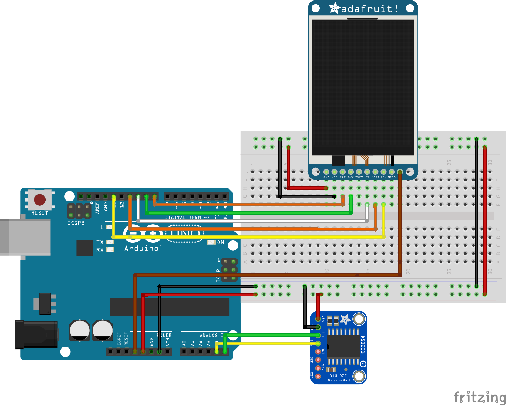
Schematics
We will replace the 16×2 LCD display in the schematics from the previous tutorial with the 1.8″colored TFT display. Connect the components as shown in the schematics below.
Schematics
For clarity, the pin connection between the components is described below.
Go over the connections once more to ensure everything is as it should be.
Code
The code for this project is fairly simple, we will use two main libraries; the Sodaq library which can be downloaded from this link and is used to communicate with the DS3231 and the ST7735 Arduino library to communicate with the ST7735 TFT Display.
The first thing we do in the code is to include the libraries that will be needed for this project. In addition to the two libraries mentioned above, we will add the Adafruit GFX library, the SPI library, and the wire.h library.
   /////////////////////////////////////////////////////////////////
   //         Arduino Real Time Clock fahrenheit         v1.02    //
  //       Get the latest version of the code here:              //
 //       http://educ8s.tv/arduino-real-time-clock/             //
/////////////////////////////////////////////////////////////////


#include <Adafruit_ST7735.h>
#include <Adafruit_GFX.h>
#include <Wire.h>
#include "Sodaq_DS3231.h"
#include <SPI.h>
Next, we declare the pins of the Arduino to which the TFT display is connected and create an object of the TFT class with the declared pins.
Next, we declare and initialize some of the variables used to store different information and data throughout the program.
float maxTemperature=0;
float minTemperature=200;
char charMinTemperature[10];
char charMaxTemperature[10];
char timeChar[100];
char dateChar[50];
char temperatureChar[10];
uint32_t old_ts;
float temperature = 0;
float previousTemperature = 0;
String dateString;
int minuteNow=0;
int minutePrevious=0;
With that done, we move to the setup function which we start by initializing, the TFT display, serial communication and instructing the RTC module to start communication.
Next, we create placeholders for the temperature, its max, and min value on the display.
printText("TEMPERATURE", ST7735_GREEN,30,65,1); // Temperature Static Text
printText("MAX", ST7735_RED,18,130,1);
printText("MIN", ST7735_BLUE,95,130,1);
We also include the setRTCTime() function which will be used to set the time on the RTC before it is used. After setting the time, this part of the code should be commented out and the code re-uploaded to the Arduino board.
//setRTCTime();
Next, is the void loop() function. The void loop function handles the sensing of temperature, extraction of time information from the DS3231 and the display of information on the TFT display. Since the changes of the environment temperature are slow, we will only update the temperature when there is a difference between the last temperature displayed on the screen and current temperature. This is done to counter a major downside of the 1.8″ TFT display, which is the slow speed with which the screen is updated when new information is sent to it.
The slow speed leads to the occurrence of a visible flicker on the TFT display and makes things a little bit messy. To solve this problem, we will be leveraging on the fact that we can update a section of the TFT display, without updating the whole display. This means a faster update time as less information will be passed up to the screen reducing the processing time and eliminating the resulting flicker.
The complete code for this project is given below and can be downloaded from the downloads section.
/////////////////////////////////////////////////////////////////
// Arduino Real Time Clock fahrenheit v1.02 //
// Get the latest version of the code here: //
// http://educ8s.tv/arduino-real-time-clock/ //
/////////////////////////////////////////////////////////////////
#include <Adafruit_ST7735.h>
#include <Adafruit_GFX.h>
#include <Wire.h>
#include "Sodaq_DS3231.h"
#include <SPI.h>
#define TFT_CS     10
#define TFT_RST    8
#define TFT_DC     9
Adafruit_ST7735 tft = Adafruit_ST7735(TFT_CS,  TFT_DC, TFT_RST);
// Option 2: use any pins but a little slower!
#define TFT_SCLK 13
#define TFT_MOSI 11
float maxTemperature=0;
float minTemperature=200;
char charMinTemperature[10];
char charMaxTemperature[10];
char timeChar[100];
char dateChar[50];
char temperatureChar[10];
uint32_t old_ts;

float temperature = 0;
float previousTemperature = 0;

String dateString;
int minuteNow=0;
int minutePrevious=0;
void setup ()
{
    tft.initR(INITR_BLACKTAB);
    tft.fillScreen(ST7735_BLACK);
    Serial.begin(57600);
    Wire.begin();
    rtc.begin();
printText("TEMPERATURE", ST7735_GREEN,30,65,1);  // Temperature Static Text
printText("MAX", ST7735_RED,18,130,1);
printText("MIN", ST7735_BLUE,95,130,1);
//setRTCTime();
}
//uint32_t old_ts;
void loop ()
{
rtc.convertTemperature();
float temperature = Celcius2Fahrenheit(rtc.getTemperature());
DateTime now = rtc.now(); //get the current date-time
uint32_t ts = now.getEpoch();
if (old_ts == 0 || old_ts != ts) {
old_ts = ts;
minuteNow = now.minute();
if(minuteNow!=minutePrevious)
{
dateString = getDayOfWeek(now.dayOfWeek())+", ";
dateString = dateString+String(now.date())+"/"+String(now.month());
dateString= dateString+"/"+ String(now.year());
minutePrevious = minuteNow;
String hours = String(now.hour());
if(now.minute()<10)
{
hours = hours+":0"+String(now.minute());
}else
{
hours = hours+":"+String(now.minute());
}
hours.toCharArray(timeChar,100);
tft.fillRect(10,0,160,65,ST7735_BLACK);
printText(timeChar, ST7735_WHITE,20,25,3);
dateString.toCharArray(dateChar,50);
printText(dateChar, ST7735_GREEN,8,5,1);
}
if(temperature != previousTemperature)
{
previousTemperature = temperature;
String temperatureString = String(temperature,0);
temperatureString.toCharArray(temperatureChar,10);
tft.fillRect(10,80,128,30,ST7735_BLACK);
printText(temperatureChar, ST7735_WHITE,35,80,3);
printText("o", ST7735_WHITE,85,75,2);
printText("F", ST7735_WHITE,100,80,3);
if(temperature>maxTemperature)
{
maxTemperature = temperature;
dtostrf(maxTemperature,3, 0, charMaxTemperature);
tft.fillRect(3,142,33,20,ST7735_BLACK);
printText(charMaxTemperature, ST7735_WHITE,10,145,1);
printText("o", ST7735_WHITE,35,140,1);
printText("F", ST7735_WHITE,41,145,1);
}
if(temperature<minTemperature)
{
minTemperature = temperature;
dtostrf(minTemperature,4, 0, charMinTemperature);
tft.fillRect(75,140,36,18,ST7735_BLACK);
printText(charMinTemperature, ST7735_WHITE,80,145,1);
printText("o", ST7735_WHITE,112,140,1);
printText("F", ST7735_WHITE,118,145,1);
}
}
}
delay(1000);
}
void setRTCTime()
{
DateTime dt(2016, 5, 4, 7, 38, 30, 3); //Year, Month, Day, Hour, Minutes, Seconds, Day of the Week
rtc.setDateTime(dt); //Adjust date-time as defined 'dt' above
}
void printText(char *text, uint16_t color, int x, int y,int textSize)
{
tft.setCursor(x, y);
tft.setTextColor(color);
tft.setTextSize(textSize);
tft.setTextWrap(true);
tft.print(text);
}
String getDayOfWeek(int i)
{
switch(i)
{
case 1: return "Monday";break;
case 2: return "Tuesday";break;
case 3: return "Wednesday";break;
case 4: return "Thursday";break;
case 5: return "Friday";break;
case 6: return "Saturday";break;
case 7: return "Sunday";break;
default: return "Monday";break;
}
}
float Celcius2Fahrenheit(float celsius)
{
return 1.8 * celsius + 32;
}
Demo
Install all the libraries, open an instance of the Arduino IDE and upload the code to the Arduino board, you should see the TFT display light up with the temperature, time and date information on display as shown in the image below.
Demo
Works? Yea!
That’s it for this tutorial guys. While this might look like an ordinary temperature and clock project, it could be the launch pad for something as cool as a thermostat to control the temperature in your home or smart farm and any other cool stuff you can think of. Feel free to share and ask any question via the comment section.
Till next time!
You can watch the video of this tutorial on youtube here.
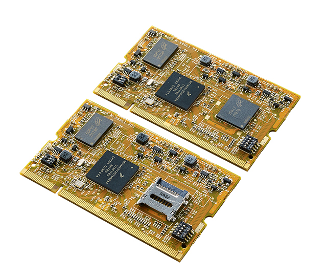
Artila Electronics, a professional in development and manufacture of ARM-based embedded Linux systems, has released a SODIMM module M-X6ULL based on NXP i.MX6ULL processor family. The new M-X6ULL is designed to meet the needs of many general embedded applications that require power efficient, high performance and cost optimized solution, as well as embedded systems that require high-end multimedia applications in a small form factor.
Artila’s M-X6ULL
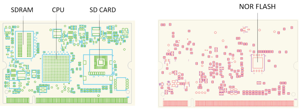
The i.MX 6ULL is a power efficient and cost-optimized processor family featuring an advanced implementation of a single Arm® Cortex®-A7 core, that can operate at speeds up to 900 MHz. The i.MX 6ULL application processor includes an integrated power management module that reduces the complexity of an external power supply and simplifies power sequencing. Each processor in this family provides various memory interfaces, including 16-bit LPDDR2, DDR3, DDR3L, raw and managed NAND flash, NOR flash, eMMC, Quad SPI and a wide range of other interfaces for connecting peripherals such as WLAN, Bluetooth®, GPS, displays and camera sensors.
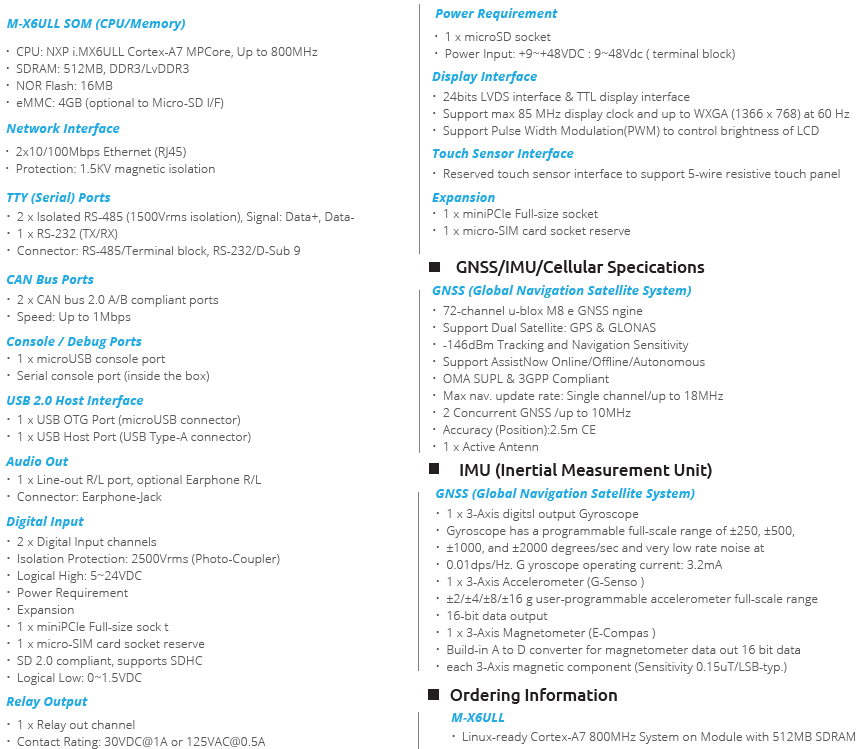
The Artila NXP i.MX 6ULL is clocked up to 800MHz and is Linux ready. The module is notable for offering Linux 4.14 with the PREEMPT_RT real-time patch which could make the module find applications in areas that needs real-time interaction. The SODIMM styled ultra-compact module measures only 68 x 42mm. The module provides support for interfaces like CAN, UART, USB, SD, LCD, GPIO, SD, Ethernet, and some others which are accessible through the module’s 200-pin expansion connector. The module ships with 512MB of DDR4 RAM, a 4GB onboard eMMC, and a 16MB NOR flash. It provides one 24bits digital parallel display interface that supports max 85MHz display clock and up to WXGA (1366 x 768) at 60Hz, a touch controller that can support 4-wire and 5-wire resistive touch panel. The module is 5V rated and consumes about 0.75 Watts.
Artila provides software packages such as PHP, Python, Perl, Node.js, and Node-RED which are available for free and the Linux BSP includes GCC 6.2.x + glibc 2.24, U-Boot, X11 GUI engine, and more. These software packages can be updated through the Artila repository by issuing the standard Linux apt-get command. The module can be booted either from the onboard eMMC or an external SD card.
Just like every other SoM board maker, Artila is providing an optional M-X6ULL starter kit to go with the module. The starter kit expands out the module microSD slot, dual Fast Ethernet ports, a USB2.0 host port, and micro-USB ports. The kit is further equipped with a 24-bit LVDS interface with resistive touch support and an audio output jack.
The specification for the starter kit is shown below:
i-MX6ULL Starter Kit Specification
The major target applications of this module are Industrial HMI & Access Control, IOT gateway, Industrial control & automation and Test and measurement. Attila’s M-X6ULL SoM is available for order but the price is not disclosed yet.
Orange Pi has been known for its several Raspberry Pi board clones and now has launched a better IoT focused board – Orange Pi 4G IoT. The Shenzhen based company, Xulong has gone through different modifications and even as at last year released a low-cost 2G based board – The Orange Pi 2G IoT board that cost just $9.90. However, recent trends have been gearing towards 4G technology, and some countries like Australia are already outfacing the old 2G networks.
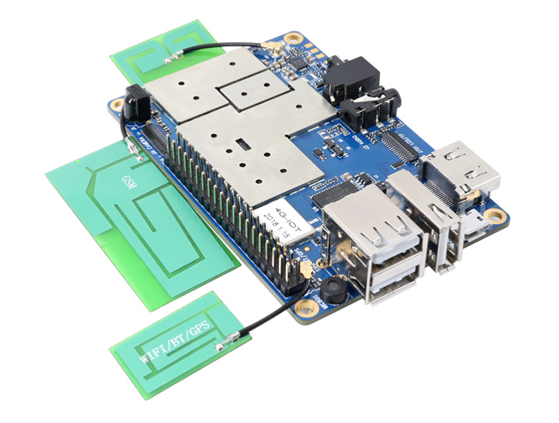
Orange Pi 4G IoT Board
Therefore, it did not come as a big shock when the company released a 4G board recently. But it is clear that Shenzhen Xulong outdid itself as the board has a lot interesting and advanced features such as its 4G LTE module, fingerprint sensor support, WiFi, GPS and many more. The Orange Pi 4G IoT board is the most advanced Orange Pi board till date. Like many other Orange Pi boards, the Orange Pi 4G – IoT has a Raspberry Pi like footprint which measurements are 85mm × 55mm and a 40 – pin expansion header.
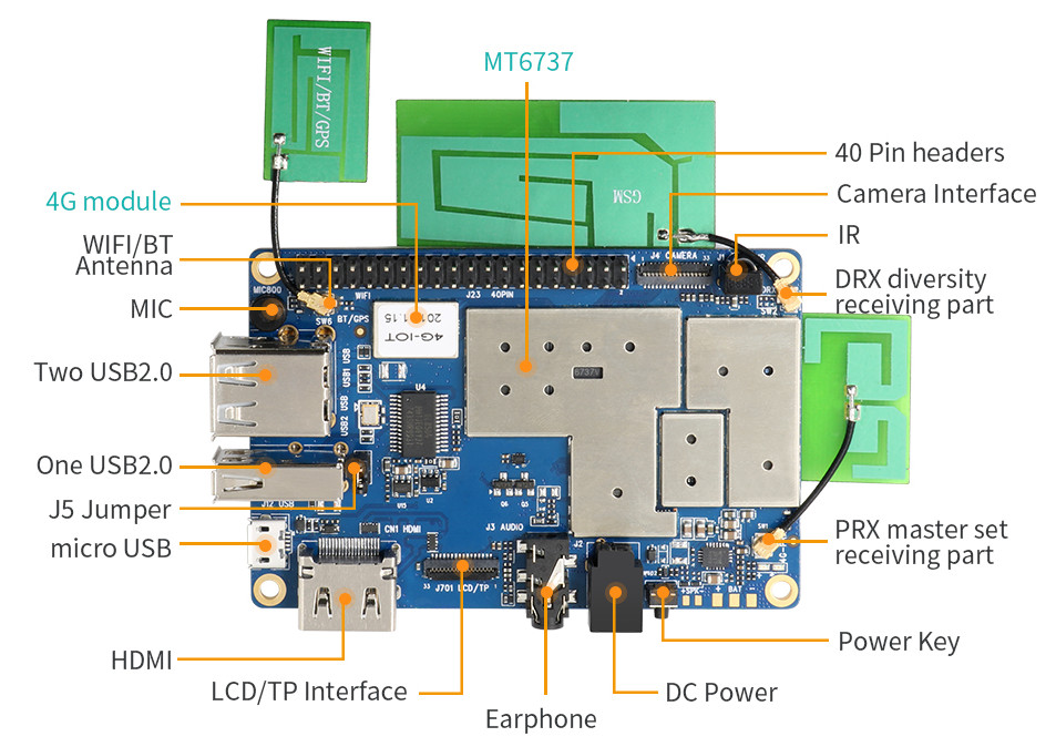
At the heart of the Orange Pi 4G IoT board is the MediaTek MT6737 SoC. The MediaTek SoC is a 64bit Quad-core, Cortex-A53 and clocked from 1.1GHz to 1.3GHz. There’s also a high-end, up to 650MHz Mali-T720 MP1 GPU with the SoC.
The Orange Pi 4G – IoT Single Board Computer (SBC) runs Andriod 6.0 has a 4G LTE radio module with a mini-SIM card slot, a fingerprint sensor support and a combo module that includes WiFi, FM, GPS, and Bluetooth. There’s also a mic and an earphone jack. The board has a PRX receiver which could be a potential source for the fingerprint reader or a proximity sensor module. The Orange Pi 4G-IOT also includes a three USB 2.0 OTG host ports, a micro-USB port, and an IR receiver.
The below are specifications of the Orange Pi 4G board:
Other features — IR receiver; 2x LEDs; PRX receiver for attaching fingerprint reader
Power — 5V 2A input; power button; battery supported
Weight — 42.5 g
Dimensions — 85 x 55mm
Operating system — Android 6.0 with C, C++, Kotlin, Java, Shell, and Python support
Although the Orange Pi 4G IoT board is not listed on the Orange Pi website and has no official product page or wiki page, it is surprisingly available for purchase on Aliexpress and costs only $45.
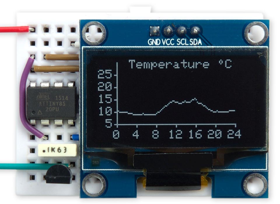
David Johnson-Davies published another great tutorial on how to use the Tiny Graphics Library to plot the outside temperature over 24 hours on a 128×64 OLED display using an ATtiny85.
This small graphics library provides point, line, and character plotting commands for use with an I2C 128×64 OLED display on an ATtiny85.
It supports processors with limited RAM by avoiding the need for a display buffer, and works with I2C OLED displays based on the SH1106 driver chip. These are available for a few dollars from a number of Chinese suppliers.
To demonstrate the graphics library I’ve written a simple application to measure the temperature every 15 minutes over a 24-hour period and display it as a live chart.