After the announcement of the i.MX 8M line of processors from NXP and their collaboration with some companies, we started seeing announcements or devices that use the chip in recent times and some of the devices or boards are beginning to be available for purchase. InnoComm, Emcraft, and Boundary devices have all launched their i.MX 8M processor-based boards, with some even adding a carrier board along with it. SolidRun, one of the announced partners with NXP back in 2017 is not left behind by releasing its own set of i.MX 8M processor-based boards.
Following their successful i.MX6 based family; SolidRun has announced a brand new family of i.MX8M based platforms, including the i.MX8 SOM, HummingBoard Pulse single board computer, and CuBox Pulse fanless mini PC. SolidRun is introducing this new family following NXP’s inclusion of the company as part of a handful of early adopting partners.
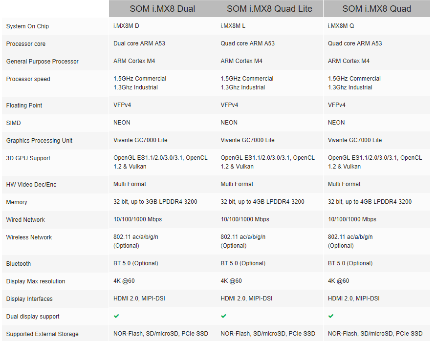
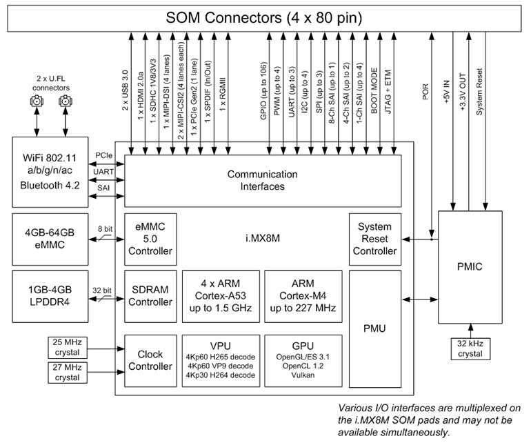
The new i.MX8 line of processors are 64-bit, ARM-based chips with support for 4K and they’re expected to come in a few different configurations. The new family will feature up to four 1.5 GHz ARM® Cortex® A53 cores with a Cortex M4 general purpose processor, high-speed connectivity interfaces and flexible memory options, offering 4K UltraHD resolution and HDR video quality, the highest levels of pro audio fidelity and up to 20 audio channels.
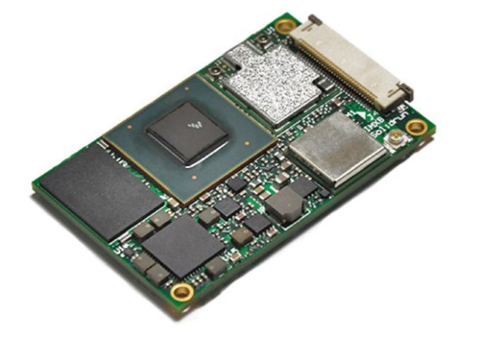
SolidRun i.MX8 SOM
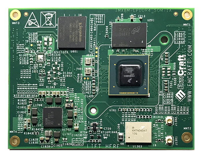
The SolidRun i.MX 8M SOM is one of the smallest system-on-module to be released measuring just 47 x 30 mm, a close comparison to the InooComm’s 50 x 50mm SOM. “The i.MX8 SOM will allow developers and OEMs to simplify the production cycle and reduce time-to-market drastically. The company’s mix-and-match concept “will allow users to easily switch between different SOM grades and configurations as needed” says SolidRun. The module is available for purchase on SolidRun site, and they come in different configurations as listed below:
i.MX8M SOM
The Dual with 1GB RAM – $80
The Quad Lite with 1GB – $90
The Quad with 2GB RAM – $105
The Dual with 1GB RAM, 8GB eMMC, and WIFi Plus BT – $140
The Quad Lite with 1GB RAM, 8GB eMMC, and WIFi Plus BT – $150
The Quad with 2GB RAM, 8GB eMMC, and WIFi Plus BT – $160
They all have Cortex-A53 cores clocked from 1.3GHz to 1.5GHz, as well as the i.MX8M‘s built-in Cortex-M4 MCU and Vivante GC7000 Lite GPU. All configurations are capable of generating 4K@60 video with HDR.
For more information about the i.MX8M SOM specification see below and check here also.
SolidRun i.MX8M SOM Specification.
HummingBoard Pulse
The HummingBoard Pulse is released as part of SolidRun’s HummingBoard family of SBCs and offers the flexibility and features of the HummingBoard platform paired with the abilities of the i.MX8M processor. The sandwich-style, i.MX8 SOM based HummingBoard Pulse SBC is larger than the original, Raspberry Pi-sized HummingBoard-Pro, which ranked among the earliest open source SBCs on the market.
HummingBoard Pulse SBC
HummingBoard Pulse houses the powerful i.MX8 SOM with either the quad or dual-core ARM Cortex A53 processor configuration. This SBC features up to 4GB LPDDR4 memory, with flexible storage options including eMMC and MicroSD slot. HummingBoard Pulse also offers a range of connectivity options, including USB type C, 2 USB 3.0 ports, Mini PCIe, M.2 and even a SIM card slot. All on a compact ARM-based and energy efficient SBC measuring only 102mm X 69mm.
The HummingBoard is available for purchase here and also comes with different configuration options –
HummingBoard Pulse Quad 1.3GHz NXP i.MX8 with 2GB RAM, 8GB eMMC and WiFi plus BT – $240
They all support 7-36V power input, comes with a standard heatsink, and an optional metal enclosure. Despite the i.MX8 SOM‘s industrial temperature support, the Pulse is limited to 0 to 70°C.
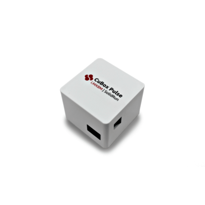
CuBox Pulse
CuBox Pulse is a powerful and tiny mini PC based on the i.MX8M processor. The mini-PC measured at only 2″ x 2″ x 2″, the same dimensions as older CuBox mini-PCs. The Cubox Pulse will be great for applications in the areas of home entertainment, digital signage and a host of multimedia-center applications as a result of its 4K UltraHD @60Hz, Dolby Vision and full HDR.
Cubox Pulse mini Pc
CuBox Pulse will be offered in some configurations based around the i.MX8 Dual, Quad and Quad Lite SOMs. It integrates a microSD slot, 2x USB 3.0 ports, an HDMI 2.0 port, and a GbE port with PoE sink support. There’s also a 12V DC input, an RTC, and an IT receiver. The temperature range is 0 to 70°C as seen in the Hummingboard.
The Cubox pulse is available for purchase online in various configurations from $170 to $190. You can choose from the 1GB RAM Dual or 2GB Quad models of the i.MX8 SOM, both with 8GB eMMC and WiFi/Bluetooth.
“NXP’s new i.MX8M processor is a true game-changer with enhanced processing and multimedia features,” states SolidRun CTO Rabeeh Khoury. “Our new i.MX8 based family harnesses the massive benefits of the new processor, and offers developers a set of modular, flexible and powerful platforms for development or as ready to use solutions.” More information can be found in SolidRun’s i.MX8 SOM, Hummingboard Pulse, and CuBox Pulse product pages.
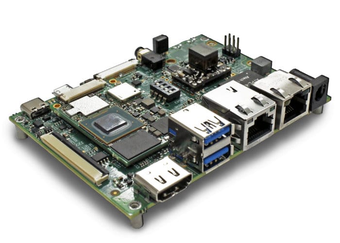
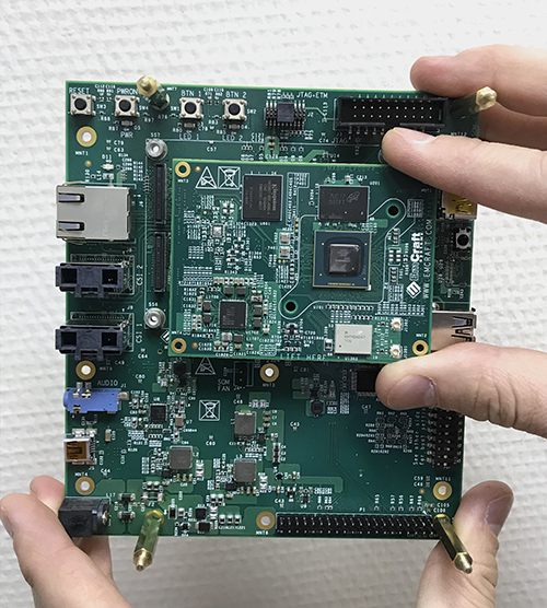
Emcraft, which is known primarily for its work in porting uClinux to various high-end MCUs recently unveiled its NXP i.MX 8M System On Module (SOM) which is Linux driven and a Starter Kit for the i.MX 8M SoM. The starter kit gives Gbe, HDMI 2.0, USB 3.0, USB Type C and a Raspberry compatible 40 pin connection.
Emcraft i.MX 8M System-On-Module (SOM)
The 60 mm * 80 mm module is a mezzanine module that supports 512MB to 4GB of DDR3L or LPDDR4 RAM, up to 64GB eMMC 5.0 flash, a PMIC interface that supports WiFi-ac and Bluetooth 4.2 module with dual U.FL connectors. The i.MX 8M features up to four Cortex-A53 cores at 1.5GHz and a Cortex-M4 core for low-power and real-time operation.
The i.MX 8M SoM Starter Kit extends out the features of the i.MX 8M SoM. The board features GbE, USB Type-C, USB 3.0 host, and micro-USB serial console ports. It also comes with some media interfaces like an HDMI 2.0 port, dual MIPI-CSI camera interface, and an audio I/O jack. The BSB baseboard also comes with a Raspberry Pi compatible 40 pin header, a 12V jack, dual Light Emitting Diodes (LEDs), an IR receiver, reset and multiple push buttons and a boot selection switch. The board supplies the Arm JTAG and Arm JTAG+ETM debug connectors. The block diagram also shows a Peripheral Component Interconnect Express-based M.2 expansion socket, a Real Time Clock with battery holder, and a Secure Digital (SD) slot.
Starter Kit
Emcraft supports Linux as an operating system for the i.MX 8M Cortex-A53 processor core. All i.MX 8M System-On-Modules come preloaded with Linux and U-Boot. Full source files of U-Boot and the Linux BSP are provided for free download, along with the Linux distribution and cross-development environment. Both U-Boot and Linux are royalty-free making it easy to incorporate into commercial products.
The Starter kit is available for pre-orders online for $349 and has shipping scheduled for May 2018. More information about the i.MX 8M System On Module and the Starter kit can be found on the product page. You can find documentation about setting up the Linux environment for the Emcraft i.MX 8M System-On-Module (SOM) here.
Optical data transmission offers a different way of sending data between objects without the drawbacks associated with radio-frequency and wired-communications methods. Visual data communication uses light beam as the medium of data exchange. Optical data communication has applications everywhere, to the fiber-optics that pushes your connectivity to the world and even that old-school TV remote uses optical data transmission.
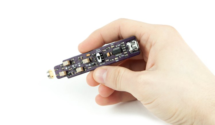
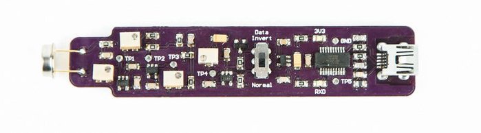
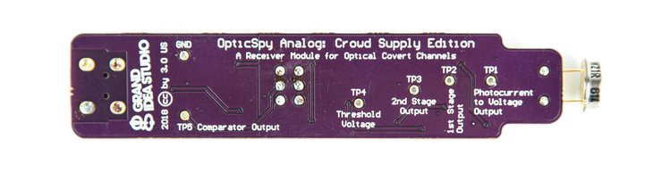
OpticSpy
Aside from application in Fiber Optics, Optical Data Communication is also growing in a space called Li-Fi, a future potential alternative to Wi-Fi, where internet is transmitted through light beams. All these are generating more interest in this technology and makers are not left behind, thanks to a tool called OpticSpy. Ever want to be able to figure out what information a TV remote sends out to your TV? Or even what does those blinkenlights on your device, router or server is saying? OpticSpy might be the right tool to find out.
The OpticSpy modules provide a platform to explore, evaluate, and experiment with covert optical channels. They capture, amplify, and convert an optical signal or light signal into a digital form that can be analyzed or decoded with a computer. OpticSpy is excellent for exploring and experimenting with optical data transmission. OpticSpy is maker friendly, not only because it is open source hardware, but also it can connect directly to an Arduino, Logic Analyzer, and even a Raspberry Pi to process the raw data.
At the core of the OpticSpy design is the Maxim based Photodiode Receiver that can handle fiber-optic data rates up to 800kbps, a small potentiometer for fine-tuning a particular target signal, and an onboard USB-to-Serial interface for connection to a serial host device. OpticSpy is powered from the host computer’s USB port and uses an FTDI FT231X USB-to-Serial IC to provide the USB to Serial connectivity. When connected to a computer, OpticSpy will appear as a Virtual COM port and will have a COM port number automatically assigned to it. A terminal program like Putty or CoolTerm can be used to communicate to OpticSpy for reading of its decoded signal. It has been successfully tested with both visible and near-infrared light sources.
OpticSpy is going to give electronics hobbyists and hardware hackers ability to search for convert channels on existing modern devices, clone a device transmission, and even add optical data transfer functionality to a project. Some areas OpticSpy could find applications are:
Add data exfiltration/transfer functionality into a project
Capture/decode/demodulate IR signals from remote controls
The OpticSpy is currently in the crowdfunding stage on Crowd Supply, with a single unit costing $49. But, for $59 you can upgrade to the OpticSpy + Tomu Bundle, which allows you to experiment with transmitting and receiving data. The campaign ends March 31st, and orders are expected to ship at the beginning of May.
Back in 2007, Technologic Systems announced the TS-7800, a single-board computer (SBC) that was able to boot Linux 2.6 in under two seconds. At its core, The TS-7800 is equipped with a Marvel 500MHz ARM9 CPU and includes a user-programmable on-board FPGA (Field-Programmable Gate Array) with 12,000 LUTs (look-up tables). The TS-7800 was a powerful board at that point and a template for other SBCs to follow in the years to come.
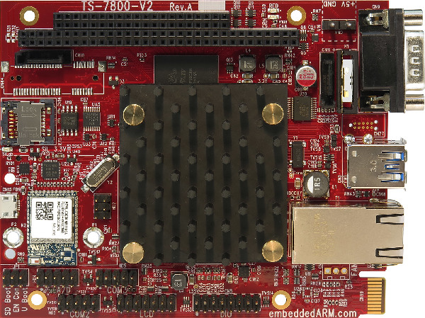
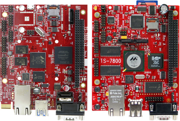
TS-7800-V2
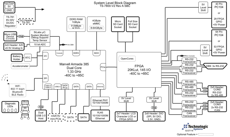
March 2018, Technologic Systems announced their latest single board computer, the TS-7800-V2. The TS-7800-V2 is a significant upgrade of their 2017 debuted TS-7800 V1 SBC and replaced the core features of the TS-7800. Technologic has swapped out the old ARM9 based, 500MHz Marvel Orion 88F5182 processor for the faster Marvell 1.3GHz Armada 385 ARM Cortex A9 high-performance dual-core CPU. The Marvel Armada 385 is designed to provide extreme performance for applications which demand high reliability, fast bootup/startup, and consistent connectivity.
Just like the TS-7800 offers backward compatibility to the TS-72xx boards, the TS-7800-V2 also maintains compatibility to the V1 model in areas of electrical, mechanical, software and measures just about 119 x 97mm.
The TS-7800-V2 CPU, the Armada 385 can work up to 1.8GHz if one goes with the commercial temperature option instead of the default -40 to 85°C version. It also offers a faster companion FPGA at 20K LUTs as compared to the 12K LUT of the TS-7800. The TS-7800-V2 ships with 1GB RAM, 2GB to 64GB eMMC, and both SD and microSD slots. Additionally it offers a SATA interface, an option for increasing the device memory space and PC/104 expansion slot. The TS-7800-V2 is equipped with Gigabit Ethernet port for networking, dual USB host ports, a micro-USB console port, an RS232 port, a CAN header, accelerometer, watchdog, an onboard ADC, Real-time clock, DAC and other features.
The following are the device specifications:
Processor – Marvell Armada 385 Dual-Core 1.3GHz ARM CPU
RAM – 1 GB RAM
Flash – 4GB MLC eMMC, which can be configured to a more robust 2GB SLC eMMC
Networking –
Gigabit Ethernet
Optional WiFi 802.11 b/g/n and Bluetooth 4.0 BLE module
External Storage –
Full-size SD socket
microSD socket
2X SATA port
Optional mSATA socket
Other I/O –
2x USB 3.0 host ports
1x USB device port for console
10x Serial/COM port
2x RS-485 or optional 1x full duplex RS-485/RS-422 port
CAN Bus
SPI Bus
I2C Bus
110x GPIO
FPGA – 20k LUT Cyclone FPGA (145 various I/O pins)
Power – 5 VDC with optional daughter card for 8V-28V support
Operating Temperature – Fanless industrial range of -40 to 85 °C
Dimensions – 97 x 119mm
Operating system – Debian Linux
TS-7800 V2 Block Diagram
The TS-7800-V2 SBC runs Debian Jessie with Linux Kernel 4.4.8. The SBC starts at $279 in single units, with volume discounts reaching $229. More information may be found on Technologic Systems TS-7800-V2 product page.
The TS-7800-V2 is truly a high end, general purpose single board computer ideal for smart devices, auto entertainment systems, medical systems, enterprise-class intelligent control, plant automation, or any industrial embedded systems.
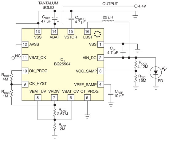
The bq25504 from Texas Instruments is a good candidate to become a milestone on the road to micro-power management and energy harvesting. A prominent feature of this IC is its ability to start up at a supply voltage as low as 330 mV typically, and 450 mV guaranteed. With an SMD inductor and a few capacitors and resistors, it forms a dc-dc converter with a high power efficiency that is unprecedented, especially in the ultralow-power region.
DC-DC converter starts up and operates from a single photocell – [Link]
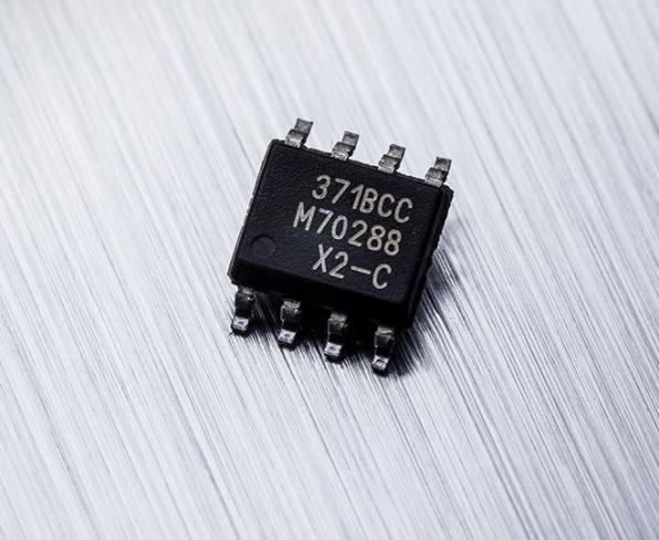
Melexis’ next-generation monolithic magnetic sensor family, consisting of the MLX90371 and MLX90372, provides robust absolute position sensing for various applications. By Julien Happich @ eenewseurope.com:
Both devices consist of a Triaxis Hall magnetic front end, an analog to digital signal conditioner, a DSP for advanced signal processing and an output stage driver. Due to the Integrated Magneto Concentrator (IMC) they are sensitive to magnetic flux in three planes (X, Y & Z). This facilitates the decoding of the absolute rotary or linear position of any moving magnet, enabling the design of non-contact position sensors. The MLX90371 offers analog or PWM output while the MLX90372 offers SENT (SAE J2716 rev Apr 2016) or PWM output.
Triaxis magnetic position sensor IC is ASIL-ready – [Link]
Get the benefit of enhanced system design through the newest features at the same or lower price with a longer-term assurance of supply.
ACPL-352J: This 5A gate drive optocoupler is a device with integrated fail-safe IGBT and MOSFET diagnostics, protection and fault reporting.
ACPL-C799is a 1-bit, second-order sigma-delta (Σ-Δ) modular that converts an analog input into a high-speed data stream with galvanic isolation based on optical coupling technology.
AFBR-57E6APZ-HT: Low Power 125MBd SFP Transceiver for Fast Ethernet & FDDI (-40°C to +95°C Temperature).
AFBR-59E4APZ-HT: The AFBR-59E4APZ-HT is a new power-saving Small Form Factor transceiver that gives the system designer a product to implement a range of solutions for multimode fiber Fast Ethernet.
AEDR-8700 Series: The Broadcom AEDR-871x is a 3-channel reflective optical encoder device providing dual channel quadrature digital outputs and an index channel digital output.
Hi guys, welcome to this tutorial. Today, we will build an mp3 player using an Arduino and the DFPlayer mini MP3 module.
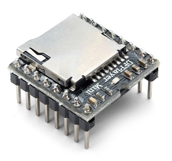
The DFplayer mini is a small, low-cost mp3 module with a simplified audio output that can be connected directly to a speaker or an earphone jack. The module can be used as a stand-alone module with attached battery, speaker, and push buttons or used in combination with a microcontroller or development board like the Arduino, enabled for RX/TX (Serial) communication, thus through simple serial commands we can play music and perform other functions like playing the next and previous song, shuffle, pause the song currently being played etc. The module comes with an SDcard slot and supports both FAT16, FAT32 file system.
MP3 player using Arduino and DFPlayer mini – [Link]
Hi guys, welcome to this tutorial. Today, we will build an mp3 player using an Arduino and the DFPlayer mini MP3 module.
The DFplayer mini is a small, low-cost mp3 module with a simplified audio output that can be connected directly to a speaker or an earphone jack. The module can be used as a stand-alone module with attached battery, speaker, and push buttons or used in combination with a microcontroller or development board like the Arduino, enabled for RX/TX (Serial) communication, thus through simple serial commands we can play music and perform other functions like playing the next and previous song, shuffle, pause the song currently being played etc. The module comes with an SDcard slot and supports both FAT16, FAT32 file system.
Some of the features of the DF player mini include:
Support of sampling rate of 8KHz, 11.025KHz, 12KHz, 16KHz, 22.05KHz, up to 48KHz
24-bit DAC output, dynamic range support 90dB, SNR supports 85dB
Supports FAT16, FAT32 file system, maximum support 32GB TF card
A variety of control modes, serial mode, AD key control mode
The broadcast language spots feature, you can pause the background music being played
Built-in 3W amplifier
The audio data is sorted by folder; supports up to 100 folders, each folder can be assigned to close to 1000 songs
30 levels of volume adjustable, 10 levels EQ adjustable.
The goal of this tutorial is to demonstrate the use of this module with Arduino, using the push buttons to instruct the Arduino to send serial commands to the module and control mp3. We will use three buttons to achieve this. The first button will serve as the “previous” button that will enable us to play the previous song. The second button will be to “play/pause” the file currently being played and the third button will be used to play the next file.
Required Components
The following components are required to build this project;
As usual, each of this components can be bought via the link attached to them in the list above.
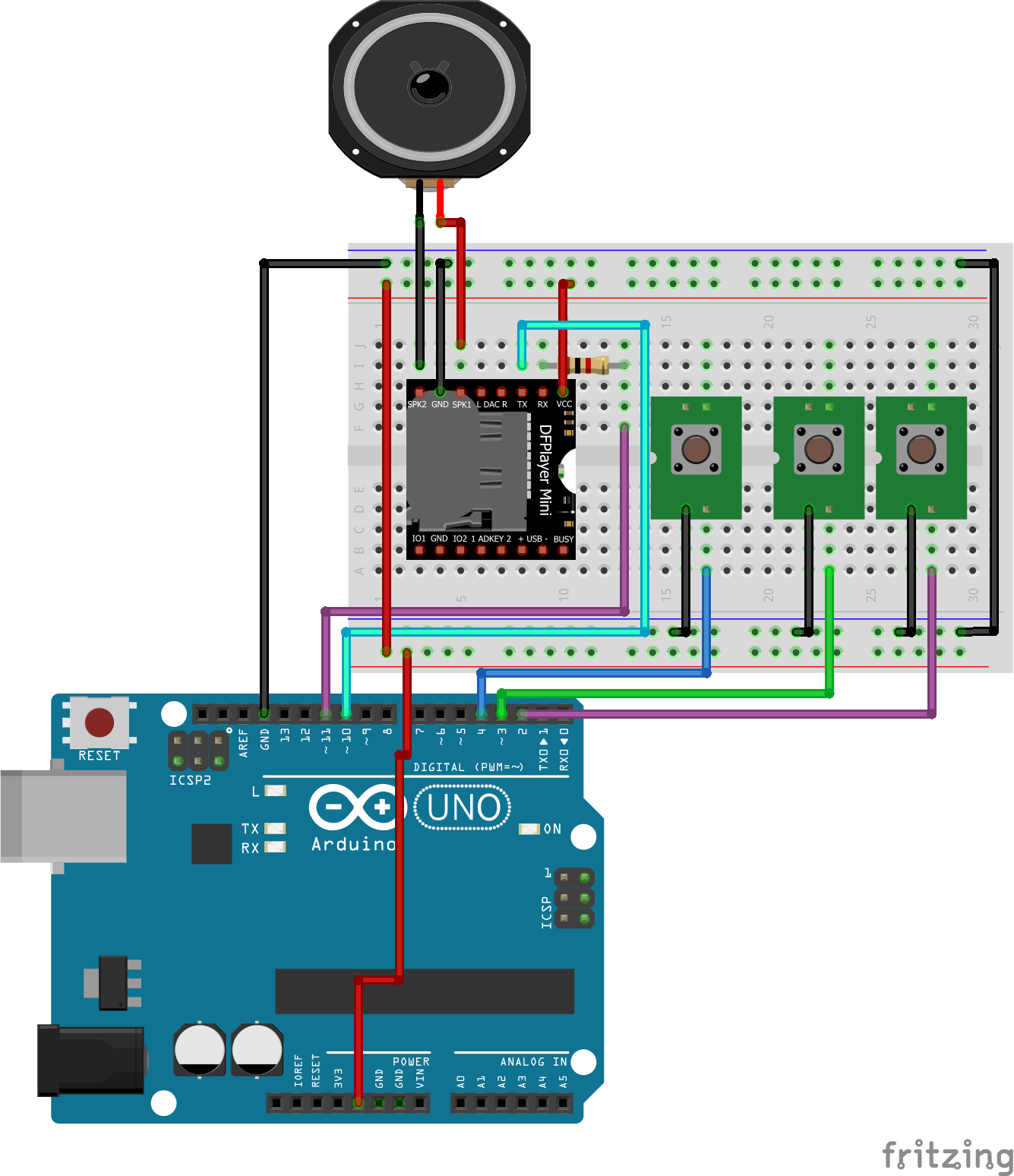
Schematics
The schematics for this project is fairly easy
Schematics
As seen above the connection between the Arduino and the DFplayer mini is very simple as we only need to connect two pins aside VCC and GND. It should be noted that the 1k resistor added in between the Rx pin of the module and the Arduino was added to reduce noise but it’s not necessary if your module setup is not accompanied with noise on the Rx line. The connection is described below for clarity.
DFplayer Mini – Arduino
Rx - D11
Tx - D10
VCC - 5v
Gnd - Gnd
Go over the connections once again to ensure everything is as it should be. Our switches are intentionally connected without pull up (or down) resistors because we will enable the Arduino internal pull up resistors.
Code
To send commands from the Arduino to the DFplayer mini, based on the button pressed, we will use the Arduino software serial library. While we could have used the hardware serial to send commands from the Arduino to the DFplayermini, the Arduino hardware serial pins (0 and 1) are the same pins used by the Arduino to communicate with the computer and may prevent code to uploaded smoothly if connected to any other device. So to communicate in a stress-free manner we will use the software serial library with pins 10 and 11.
The code for this tutorial is simple, while the DFPlayer mini has a library which contains different functions for controlling the mp3 player, we will write our own functions for the fun of it and to help show how the module really works.
The first thing we do in the code, as usual, is to include the libraries that we will use which in this case is the software serial library, creating an object of the library while declaring the Rx and Tx pins (10 and 11 respectively).
Next, we define some of the commands that we will use specifying the hex values.
# define Start_Byte 0x7E
# define Version_Byte 0xFF
# define Command_Length 0x06
# define End_Byte 0xEF
# define Acknowledge 0x00 //Returns info with command 0x41 [0x01: info, 0x00: no info]
Next, we declare the pins of the Arduino to which the push buttons are connected.
int buttonNext = 2;
int buttonPause = 3;
int buttonPrevious = 4;
Next, we move to the void setup function where we set the pin mode of the pins to which the buttons are connected and set those pins “high”. With this done we start the software serial communication with a 9600 baud rate.
Next, we play the first song on the storage device using the playfirst() function and set the isPlaying boolean variable to true to indicate that one of the files is currently playing.
delay(1000);
playFirst();
isPlaying = true;
Moving to the void loop function, this function basically checks for the button press and sends the corresponding command to the DFPlayer mini which then either plays (depending on the value of the “isplaying” variable) or pause the current song, or go to the next or previous song.
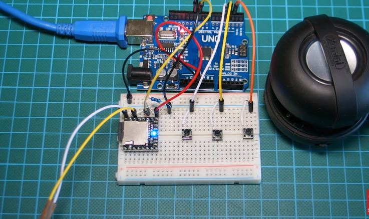
Load an SD card with songs and insert into the DFplayer mini, then upload the code to your Arduino and connect the wires from speaker to the speaker pins of the DFPlayer mini. You should hear songs start streaming out from the connected speaker. Your final setup should look like the image below.
Hardware Setup
Some of the applications of this tutorials are listed below and I hope it gives you the inspiration to build something really cool.
Applications
Fire alarm voice prompts
Toll stations voice prompts
Electricity, communications, financial business hall voice prompts
Multi-channel voice alarm or equipment operating guide voice
That’s it for this tutorial guys, thanks for following. If you get stuck anywhere feel free to send your questions via the comment section.
Till next time!
The video tutorial for this tutorial can be watched on youtube here.