Hi guys, welcome to today’s tutorial. Today, we will look on how to use the 1.8″ ST7735 colored TFT display with Arduino. The past few tutorials have been focused on how to use the Nokia 5110 LCD display extensively but there will be a time when we will need to use a colored display or something bigger with additional features, that’s where the 1.8″ ST7735 TFT display comes in.

The ST7735 TFT display is a 1.8″ display with a resolution of 128×160 pixels and can display a wide range of colors ( full 18-bit color, 262,144 shades!). The display uses the SPI protocol for communication and has its own pixel-addressable frame buffer which means it can be used with all kinds of microcontroller and you only need 4 i/o pins. To complement the display, it also comes with an SD card slot on which colored bitmaps can be loaded and easily displayed on the screen.
Other features of the display include:
- 1.8″ diagonal LCD TFT display
- 128×160 resolution, 18-bit (262,144) color
- 4 or 5 wire SPI digital interface
- Built-in microSD slot – uses 2 more digital lines
- 5V compatible! Use with 3.3V or 5V logic
- Onboard 3.3V @ 150mA LDO regulator
- 2 white LED backlight, a transistor connected so you can PWM dim the backlight
- 1×10 header for easy breadboarding
- 4 x 0.9″/2mm mounting holes in corners
- Overall dimensions: 1.35″ x 2.2″ x 0.25″ (34mm x 56mm x 6.5mm)
- Current draw is based on LED backlight usage: with full backlight draw is ~50mA
The goal of this tutorial is to demonstrate the abilities of the TFT to display images and text in different colors and some animation.
Required Components
The following components are needed for this tutorial:
As usual, the exact components used for this tutorial can be bought by following the link attached to each of the components above.
Schematics
The schematics for this project is fairly easy as the only thing we will be connecting to the Arduino is the display. Connect the display to the Arduino as shown in the schematics below.

Due to variation in display pin out from different manufacturers and for clarity, the pin connection between the Arduino and the TFT display is mapped out below:
1.8″ TFT – Arduino
LED - 3.3v
SCK - D13
SDA - D11
DC - D9
Reset - D8
CS - D10
GND - GND
VCC - 5v
Double check the connection to be sure everything is as it should be. All good? now we can proceed to the code.
Code
We will use two libraries from Adafruit to help us easily communicate with the LCD. The libraries include the Adafruit GFX library which can be downloaded here and the Adafruit ST7735 Library which can be downloaded here.
We will use two example sketches to demonstrate the use of the ST7735 TFT display. The first example is the lightweight TFT Display text example sketch from the Adafruit TFT examples. It can be accessed by going to examples -> TFT -> Arduino -> TFTDisplaytext. This example displays the analog value of pin A0 on the display. It is one of the easiest examples that can be used to demonstrate the ability of this display.

The second example is the graphics test example from the more capable and heavier Adafruit ST7735 Arduino library. I will explain this particular example as it features the use of the display for diverse purposes including the display of text and “animated” graphics. With the Adafruit ST7735 library installed, this example can be accessed by going to examples -> Adafruit ST7735 library -> graphics test.
To briefly explain the example,
The first thing, as usual, is to include the libraries to be used after which we declare the pins on the Arduino to which our LCD pins are connected to. We also make a slight change to the code setting reset pin as pin 8 and DC pin as pin 9 to match our schematics.
#include <Adafruit_GFX.h>    // Core graphics library
#include <Adafruit_ST7735.h> // Hardware-specific library
#include <SPI.h>


// For the breakout, you can use any 2 or 3 pins
// These pins will also work for the 1.8" TFT shield
#define TFT_CS     10
#define TFT_RST    8  // you can also connect this to the Arduino reset
                      // in which case, set this #define pin to 0!
#define TFT_DC     9
Next, we create an object of the library with the pins to which the LCD is connected on the Arduino as parameters. There are two options for this, feel free to choose the most preferred.
Adafruit_ST7735 tft = Adafruit_ST7735(TFT_CS,  TFT_DC, TFT_RST);

// Option 2: use any pins but a little slower!
#define TFT_SCLK 13   // set these to be whatever pins you like!
#define TFT_MOSI 11   // set these to be whatever pins you like!
//Adafruit_ST7735 tft = Adafruit_ST7735(TFT_CS, TFT_DC, TFT_MOSI, TFT_SCLK, TFT_RST);
Next, we move to the void setup function where we initialize the screen and call different test functions to display certain texts or images. These functions can be edited to display what you want based on your project needs.
void setup(void) {
  Serial.begin(9600);
  Serial.print("Hello! ST7735 TFT Test");

  // Use this initializer if you're using a 1.8" TFT
  tft.initR(INITR_BLACKTAB);   // initialize a ST7735S chip, black tab

  // Use this initializer (uncomment) if you're using a 1.44" TFT
  //tft.initR(INITR_144GREENTAB);   // initialize a ST7735S chip, black tab

  Serial.println("Initialized");

  uint16_t time = millis();
  tft.fillScreen(ST7735_BLACK);
  time = millis() - time;

  Serial.println(time, DEC);
  delay(500);

  // large block of text
  tft.fillScreen(ST7735_BLACK);
  testdrawtext("Lorem ipsum dolor sit amet, consectetur adipiscing elit. Curabitur adipiscing ante sed nibh tincidunt feugiat. Maecenas enim massa, fringilla sed malesuada et, malesuada sit amet turpis. Sed porttitor neque ut ante pretium vitae malesuada nunc bibendum. Nullam aliquet ultrices massa eu hendrerit. Ut sed nisi lorem. In vestibulum purus a tortor imperdiet posuere. ", ST7735_WHITE);
  delay(1000);

  // tft print function!
  tftPrintTest();
  delay(4000);

  // a single pixel
  tft.drawPixel(tft.width()/2, tft.height()/2, ST7735_GREEN);
  delay(500);

  // line draw test
  testlines(ST7735_YELLOW);
  delay(500);

  // optimized lines
  testfastlines(ST7735_RED, ST7735_BLUE);
  delay(500);

  testdrawrects(ST7735_GREEN);
  delay(500);

  testfillrects(ST7735_YELLOW, ST7735_MAGENTA);
  delay(500);

  tft.fillScreen(ST7735_BLACK);
  testfillcircles(10, ST7735_BLUE);
  testdrawcircles(10, ST7735_WHITE);
  delay(500);

  testroundrects();
  delay(500);

  testtriangles();
  delay(500);

  mediabuttons();
  delay(500);

  Serial.println("done");
  delay(1000);
}
Next, is the void loop function. The void loop function for this project basically inverts the display after 500 ms.
void loop() {
tft.invertDisplay(true);
delay(500);
tft.invertDisplay(false);
delay(500);
}
All the functions called under the void setup function, perform different functions, some draw lines, some, boxes and text with different font, color and size and they can all be edited to do what your project needs.
The complete code for this is available under the libraries example on the Arduino IDE. Don’t forget to change the DC and the RESET pin configuration in the code to match the schematics.
Demo
Uploading the code to the Arduino board brings a flash of different shapes and text with different colors on the display. I captured one and its shown in the image below.
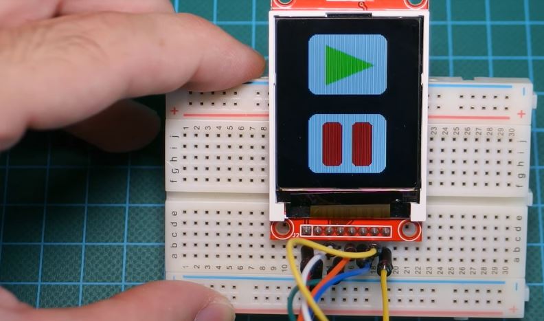
Cool right?
That’s it for this tutorial guys, what interesting thing are you going to build with this display? Let’s get the conversation started. Feel free to reach me via the comment section if you have any questions as regards this project.
Till next time!
You can watch the video of this tutorial on youtube here.