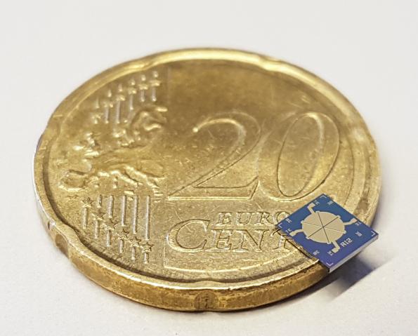
Miniature MEMS-based speakers could revolutionize speech and music reproduction in mobile communication devices. They combine the advantages of a large frequency bandwidth and high acoustic quality with the ability to generate very high sound levels. Nevertheless, they are so tiny that they can be integrated into headphones. By Christoph Hammerschmidt @ eenewseurope.com
The breakthrough has now been achieved. The characteristics of the chip-based loudspeaker are impressive: With currently a area of 4×4 millimeters, the MEMS loudspeaker can be optimally integrated into headphones, hearables and hearing aids. They cover the entire frequency range from 20 Hz to 20 kHz as a one-way system – comparable HiFi loudspeakers typically consist of woofer, a midrange loudspeaker and a tweeter for the high frequencies. The tiny MEMS speakers achieve a sound pressure level of 110 dB for in-the-ear applications – this corresponds to the noise level of a jet aircraft at a distance of 100 meters.
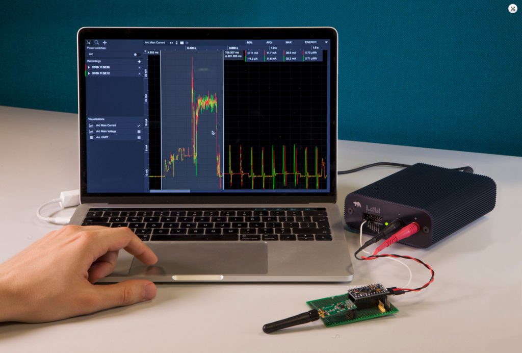
Power measurement software by Qoitech is available from Digi-Key Electronics, following the signing of a worldwide distribution agreement to distribute Otii, a power measurement tool with software.
Otii provides developers with the means to simplify power measurement of applications and devices, especially those targeting the IoT space and aiming for optimised, long battery life. Otii combines the measurement capabilities of several test and measurement hardware tools into the Otii Arc, a device that makes it substantially easier for developers to pinpoint which sections of code, associated peripherals, and hardware contribute most to the application’s power consumption.
Powered by a PC’s USB port or an external 7.0 to 9.0V power supply, the Otii Arc provides power to the target application whilst measuring and displaying power consumption from below one microA to 5.0A without the need to manually change the settings.
As well as measuring power consumption, the Otii Arc, together with the accompanying Otii software, can also monitor additional analogue and digital signals, allowing application sub-systems to be monitored in parallel to the main power input. Any serial data, from 9600bit per second to 4Mbit per second, output by the target can also be synchronously captured and time-stamped.
Qoitech’s Otii software runs on Windows, macOS and Ubuntu Linux. The developer can review power consumption from a development PC and share and compare the results with colleagues, customers and suppliers. The software increases usability when compared to traditional test and measurement tools, claims Digi-Key, as these can require results to be displayed on the tool itself, or to be exported for later analysis in a spreadsheet without the test settings and related context of the application.
Vanja Samuelsson, founder of Qoitech, says: “By combining current measurement, voltage measurement and debug logs output by the target’s serial interface, developers acquire a significantly improved view of their IoT application’s power consumption, allowing them to guarantee a battery life of up to 10 years for some applications.”
The Otii solution comes with a standard software license, but with the additional purchase of an Otii Premium License, developers can access the battery profiling, simulation and scripting capabilities of the Otii software. Using the Lua scripting language, the Otii Arc can be used to profile batteries, allowing different batches of the same cell to be compared, or to evaluate their performance under environmental conditions that more closely match that of the application. The Lua scripting also enables automated testing, allowing longer term tests to be run without human intervention.
Otii solution is available to ship immediately from Digi-Key Electronics.
The venerable Arduino Uno is the de facto standard in microcontroller development boards, but there are also other boards that can be hidden in a project to make it “smart.” Some even provide extra features like built-in Bluetooth or WiFi capabilities. While the Uno will certainly be used for years to come, due to its familiar form factor and available accessories, here are nine other options in even smaller form factors to hide in your project.
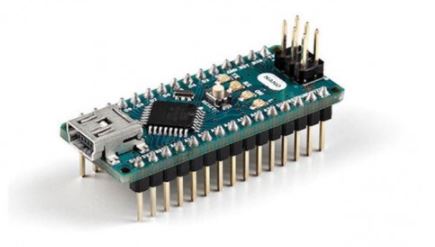
Arduino Nano
If you like the Arduino Uno, but just want it smaller, then the Arduino Nano provides very similar specs. While the Uno board measures 68.6 x 53.4mm at 25g, the Nano measures only 18 x 45mm at 7g. The Nano gets its size down by eliminating the DC power jack and utilizing Mini-B USB. Continue reading “9 Tiny Microcontroller Board Options to Complement Your Arduino Uno”
Quality is as important to us as it is to you. At Seeed Fusion, our manufacturing expertise can help you reduce errors and failure rates for a prototype or a mass-produced product. Whether there is a problem with one of the components, assembly, or the PCB design itself, any error can result in a non-functioning device which can be complicated or impossible to rectify. In the business for over 10 years, Seeed is an old hand when it comes to manufacturing electronics and implements quality control measures at every stage of its Seeed Fusion PCB Assembly service.
Gerber File Review
Quality assurance procedures begin at order submission. CAM engineers will review every set of manufacturing files to minimize design for manufacture errors before the files are sent for production. As the old saying goes, prevention is better than cure. If any problems are found such as shorts and breaks, missing holes or solder mask openings, etc. Seeed Fusion will work with the customer to review the issue and make corrections if necessary.
PCB In Production
As standard, all Seeed Fusion PCBs undergo bare PCB AOI (Automated Optical Inspection), flying needle tests, individual visual checks between each stage and then a Final Quality Control inspection. These measures cover errors with copper deposition, trace connectivity, solder mask coverage and more.
Incoming Parts Quality Inspections
Many fake, second-hand or old components are on the market, so vigilance is paramount when shopping for parts. Seeed Fusion’s PCBA service can take the risk out of parts procurement for you. Seeed preferentially orders its components from partners DigiKey, Mouser, TME and Element14 to ensure genuine and new parts direct from reliable channels.
Seeed’s own stock of parts, the Seeed Fusion Open Parts Library (OPL) also undergo strict quality control measures to fulfill high standards. All incoming stock goes through the same IQC (Incoming Quality Control) that Seeed’s own materials undergo and suppliers are trusted partners that are audited on a regular basis.
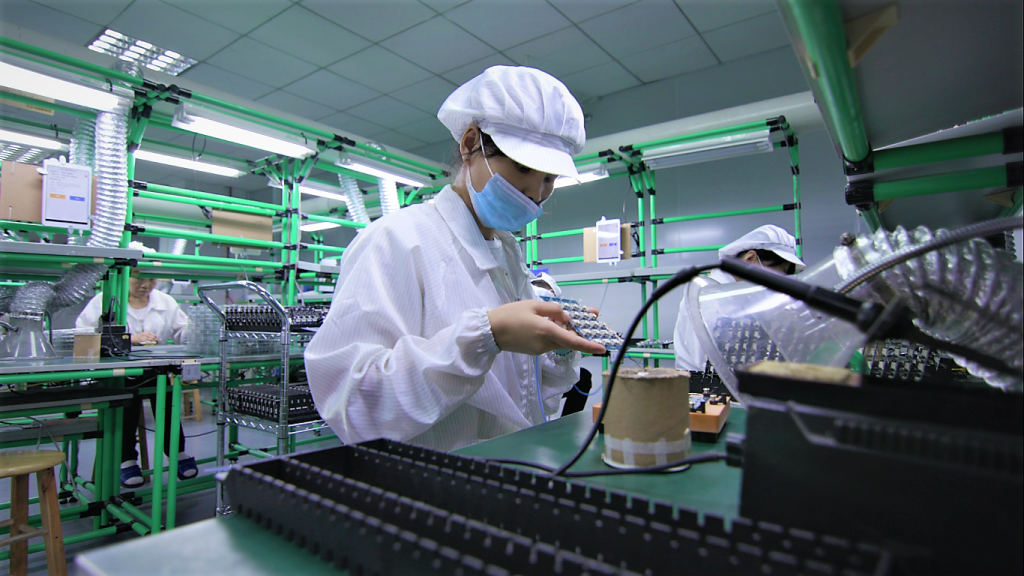
Populated PCBs queued up for inspection. Stickers highlight potentially problematic areas for further review.
Assembly Process
Seeed Fusion PCBA’s completely lead-free assembly line employs visual inspections along the entire line as well. Each operator at each stage will check for common process errors, for example, PCBs fresh from the reflow oven will be inspected for insufficient solder wetting, component tombstoning or skew, etc. and re-worked if necessary. Boards are then inspected before packing, and any issues that arise are forwarded to the customer for confirmation.
Other tests and certifications are also available such as mechanical and functional testing, In-Circuit testing, SMT AOI, X-ray inspection, FCC/CE certification and more.
By utilizing industry proven and tested quality control measures, Seeed Fusion PCBA can maximize your output and production efficiency with peace of mind and no compromises. And now is no better time to give us a try. We are currently holding March sales to help with your production needs whether it be prototyping or mass production. Get 10% off PCB upfront, $50USD off PCBA and over 400 OPL components are free just this month. Don’t forget there is also free express shipping on PCBA orders. Upload your BOM here and get a quote now!
Learn more about Seeed Fusion PCBA service from the video below:
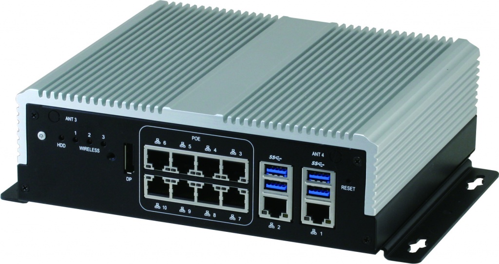
AAEON, an award-winning developer of network devices and embedded computers, launches the VPC-5600S, a network video recorder (NVR) with a possible eight PoE ports, each supported by their own LAN chips.
The VPC-5600S recently picked up coveted COMPUTEX d&i and Taiwan Excellence Awards, and AAEON network security division product manager Josh Chen has labelled it “the perfect surveillance system.” AAEON is currently the only company to offer NVRs featuring eight PoE ports with individual LAN chips. With this hardware specification and the device’s 7th Generation Intel® Core™ processor, users will receive the highest quality images from multiple sources without any danger of data loss. With an additional four USB3.0 ports and two LAN ports, the VPC-5600S can support up to 14 high-grade surveillance cameras. Continue reading “AAEON’s VPC-5600S opens up new horizons for NVR technology”
An Arduino UNO Flash and RAM update with the ATmega2560 as DIL 28 variant.
I love the Arduino UNO with the DIL 28 ATmega328. He is easy to replace and all my projects are equipped with it. But constantly either the flash memory, the RAM or both is too small. Therefore, I have developed a replacement that provides 8 times more memory. For this I went into the microcosm of the PCB construction and impressed an ATmega2560-16CU in the smallest possible layout.
Increase Arduino UNO memory with ATmega2560 – [Link]
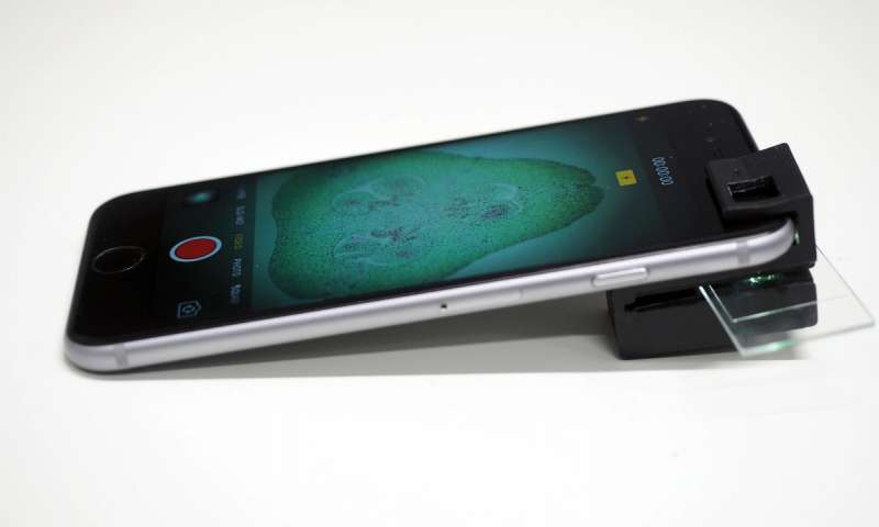
Smartphone microscope as the name implies is basically a microscope which is compatible with a user’s smartphone. They mostly made up of a soft pliable lens and uses the smartphone’s camera. Smartphone microscopes have been in existence before, they are based on the use of external LEDs and usually get powered from an external source, these attachments have been quite larger and more cumbersome than the phone itself, but a group of Australian researchers has developed a microscope attachment that doesn’t require an additional power supply or external light sources which is actually based on 3D printed material alone.
The Researchers from the ARC Center of Excellence for Nanoscale BioPhotonics (CNBP) have developed a 3D printable “clip-on” that will allow anyone to turn their smartphone into a fully functional microscope. Thinking about the weight and cost of the pre-existing smartphone microscopes, they have made a dual-mode mobile phone microscope which uses the onboard camera flash and natural light present at the scene where the microscope is to be used. If a sample is placed two focal lengths in front of the objective lens, an image is formed two focal lengths behind the tube lens.
The invention of this microscope will make sure that people unable to afford pre-existing microscopes due to the cost of the external electrical appliances to be added during assembly can now work on their research as long they have a smartphone and the 3D printable microscope. They can examine different samples ranging from plant cells to animal cells. The smartphone microscope’s design consists of a 1x magnification imaging system that is created by placing a mobile phone camera lens in front of the mobile phone’s internal phone camera module.
The difference between the 3D printable microscope and other smartphone microscopes is the illumination system of the 3D microscope since it has been designed with internal illumination tunnels. The entrance of the tunnel is placed over the camera flash. Light from the camera flash travels through the first tunnel, reflects diffusely off of the end of the tunnel and then travels back into another tunnel that is aligned to the optical axis of the objective lens and camera module.
This 3D printed based microscope has the ability to work in two different modes: the brightfield and darkfield imaging modes respectively. During the bright field mode, the microscope creates diffuse transmission illumination without the aid of an external reflective object behind the sample thereby reducing weight and cost procured upon the addition of an external electrical object. However darkfield imaging is made possible when the ambient light illuminates the sample using the sample’ glass slide. The microscope attachment is capable of viewing objects as small as 1/200th of a millimeter, making it significantly more effective than its more predecessors.
The 3D printers microscope needs only one assembly step and can be used by anyone with access to a 3D printer as the microscope clip can be printed using most makers set of 3D printers. You can get the 3D designs here if you are interested in printing out your own.
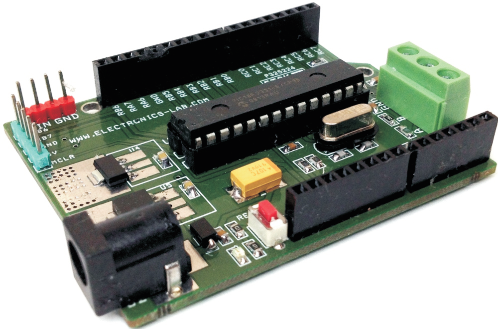
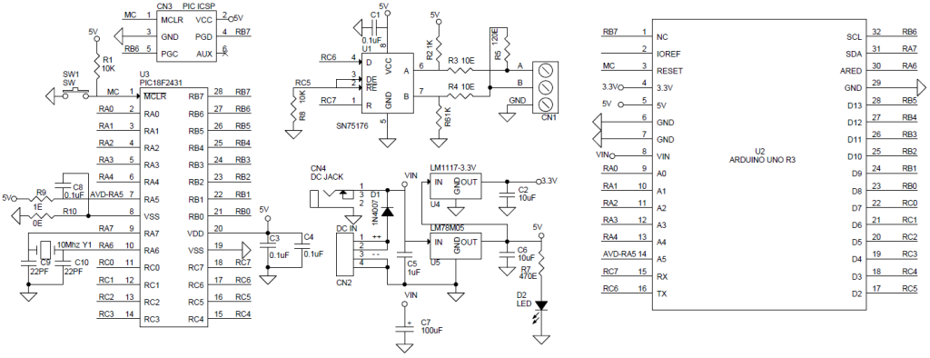
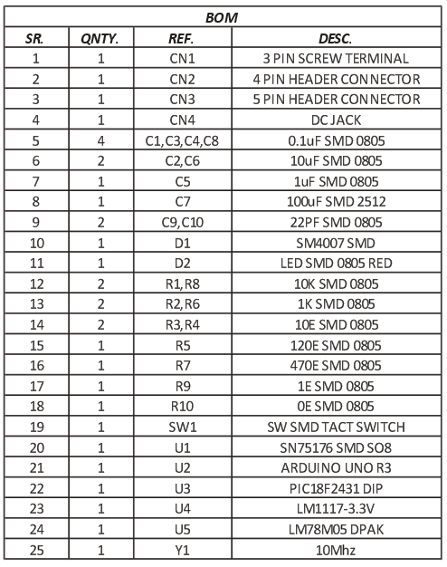
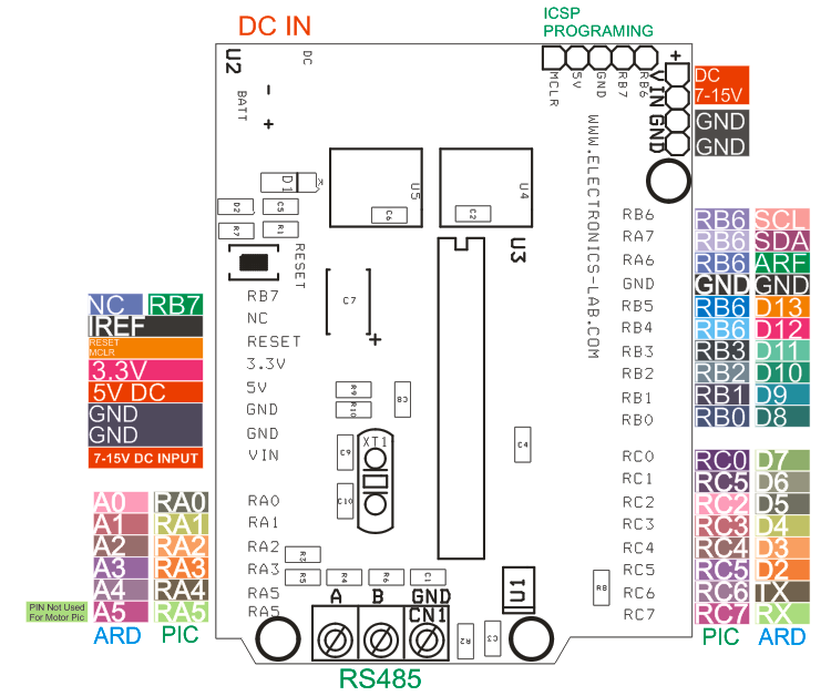
This board created for makers, who want to use various Arduino UNO shields with PIC micro-controllers from Microchip. Board facilitates the use of any 28 PIN DIP PIC microcontroller with or without crystal. Omit Y1 , C9 and C10 in case of internal oscillator . Project can also be used to develop RS485 applications with the help of on board SN75176 IC. Two regulators provide 3.3V and 5V DC outputs. ICSP connector provided to program the PIC IC using PICKIT2/PICKIT3 programmer. On board DC jack connector and additional CN2 Header connector helps to power up the board. Input supply 7V-15V DC. This board has been tested using PIC16F886 IC. The board also supports PIC18F2331 and PIC18F2431 PICs mainly used for motor applications. Solder R9 and C8 if Motor PICs are used or left open for normal microcontrollers. Switch 1 helps to reset the board. Refer to PCB top layout for Arduino to Microchip Pin configuration.
This board created for makers, who want to use various Arduino UNO shields with PIC micro-controllers from Microchip. Board facilitates the use of any 28 PIN DIP PIC microcontroller with or without crystal. Omit Y1 , C9 and C10 in case of internal oscillator . Project can also be used to develop RS485 applications with the help of on board SN75176 IC. Two regulators provide 3.3V and 5V DC outputs. ICSP connector provided to program the PIC IC using PICKIT2/PICKIT3 programmer. On board DC jack connector and additional CN2 Header connector helps to power up the board. Input supply 7V-15V DC. This board has been tested using PIC16F886 IC. The board also supports PIC18F2331 and PIC18F2431 PICs mainly used for motor applications. Solder R9 and C8 if Motor PICs are used or left open for normal microcontrollers. Switch 1 helps to reset the board. Refer to PCB top layout for Arduino to Microchip Pin configuration.
Note1 : Kindly mount following components to use this board for Motor PICs PIC18F2331 and PIC18F2431
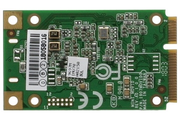
The first embedded ultra-compact Artificial Intelligence processing card for on the edge computing
UP Bridge the Gap – a brand of AAEON Europe – is proud to launch AI Core: the first embedded ultra-compact Artificial Intelligence processing cards for edge computing.
AI Core is a mini-PCIe module powered by Intel® Movidius™ Myriad™ 2 technology. This low-power module enhances industrial IoT edge devices with hardware accelerated deep learning and enhanced machine vision functionality. AAEON Technology is one of the first IPC manufacturers to address the growing need for Artificial Intelligence on the edge with dedicated hardware.
Most of the available IoT solutions are focused on connecting edge devices to the cloud and these deployments face challenges related to latency, network bandwidth, reliability and security. Experts in this field agree that not all the tasks and decision making processes can be addressed in cloud-only models. AI Core is the solution for cloud limitations by bringing AI performance and hardware acceleration not “at” but “ON” the edge of the Internet of Things.
AI Core is powered by an advanced vision processing unit: the Intel® Movidius™ Myriad™ 2 VPU. With 512 MB onboard DDR memory this mini card module requires very little energy to enable local deep-learning and computing vision algorithms. Continue reading “AI Core – Artificial Intelligence On The Edge”