Are the likes of AI and deep neural networks purely the realm of expert engineers, scientists and mathematicians?
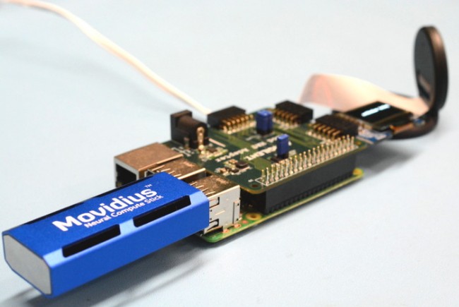
We don’t think so, so we built a Raspberry Pi 3 Model B based object-identifying appliance, using an Intel Movidius, a Pmod HAT, a Pi camera and a Digilent OLED Pmod. Find out how we got on.
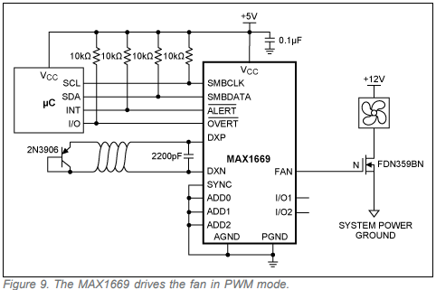
App note from Maxim Integrated about their MAX6650 and MAX6651 fan controllers chip.
Temperature-based fan control is a necessity in a growing number of systems, both to reduce system noise and to improve fan reliability. When fan control is augmented by fan-speed monitoring, a speed-control loop can be implemented that is independent of manufacturing variances and wear on the fan. In addition, a fan that is about to fail can be identified so that it can be replaced before it fails.
Two years ago, we saw the announcement of the ever lovely Raspberry Pi 3 which packed a lot of improvements to the Raspberry Pi 2. But what about making it even better? Welcome the Raspberry Pi 3 big brother – The Raspberry Pi 3 Model B+ or just called the Raspberry Pi 3 B+ and guess what? It’s being launched on March 14, the Pi day and the day we lost Stephen Hawking.
Ever since the first Raspberry Pi was launched back in 2012, we have seen a rapid improvement in the whole Raspberry Pi family and even a deviation from the standard credit-size form factor as we saw in the Raspberry Pi Zero and the Zero series (Zero W and Zero WH),. Since then it cemented its status as the undisputed “King” in the world of SBCs (Single Board Computers). The latest iteration of this family called the Raspberry Pi 3 Model B+ has the same footprint as both the Raspberry Pi 2 Model B and the Raspberry Pi 3 Model B but even greater features.
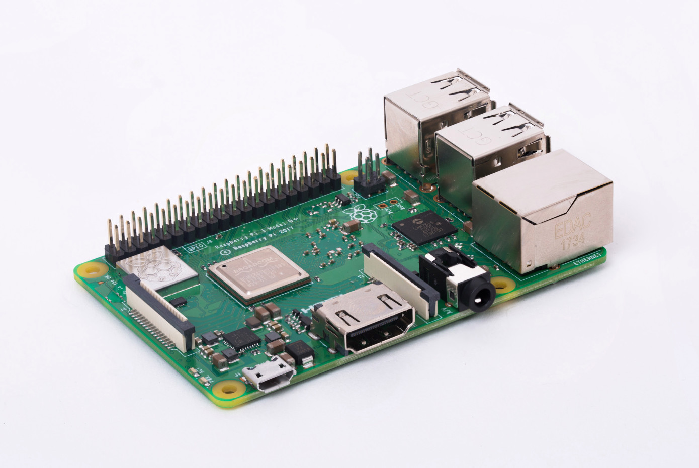
The Pi 3 Model B
The Model B+ major improvements come from its processor and networking capabilities, it sports a 64bit 1.4GHZ quad-core Broadcom BCM2837B0 processor as compared to the 1.2GHz BCM2837 chip in the Pi 3, dual-band 2.4GHz and 5GHz 802.11ac Wi-Fi connectivity, Bluetooth 4.2/BLE and Gigabit Ethernet with maximum transfer network speeds of up to 300 Mbps (three times the speed of the previous boards).
The Pi Foundation says this processor improvement is made possible as a result of improved power integrity and thermal design. The dual-band Wi-Fi on the board also comes with compliance certification, making it easy to integrate into end products without the hassle and cost of certification requirements. Just as the previous model, the Raspberry Pi 3 Model B, the Model B+ also comes with a full-size HDMI Port for video and display output, four USB 2.0 ports, a microSD port for storage purposes and booting OS, CSI ports for the Raspberry Pi camera, DSI port for connecting touchscreen displays, and also provides support for Power over Ethernet (PoE) through a PoE HAT Add-on which is sold separately.
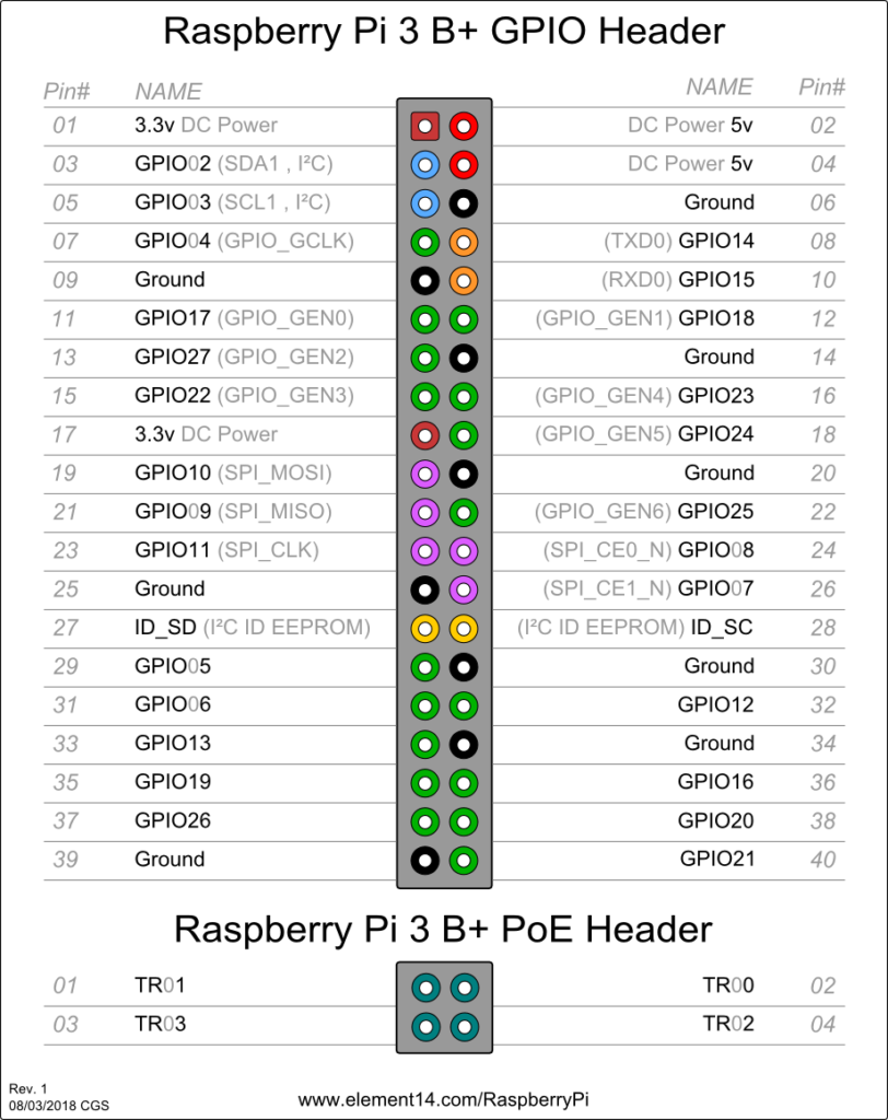
Raspberry Pi 3 Model B+ GPIO 40 Pin Block & PoE Header Pinout
source: www.element14.com
With this improvement on the Pi 3 Model B+, the hopes are high for the Raspberry Pi 4 making us wonder what would be added into the future Raspberry Pi 4, but for the time being, let’s rock our too good to be true Pi 3 Model B+. The Model B+ is available from Raspberry Pi’s official retail partners, and price remains the same too, meaning it’ll cost $35/£30 at the usual suppliers.
The drone industry is booming, and the technology is just… cool, to put it plainly. Flying robots, many of which are completely autonomous delivering our goods and also spying on us. Makers and hobbyist are getting on the bandwagon, making their customized drones with available parts. With the boom of UAV (Unmanned Autonomous Vehicle) and Drone technology also comes the growth of issues.
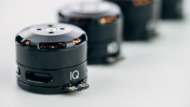
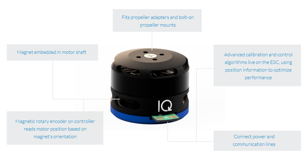
IQ Motion Module
Electric motors are one of the most fundamental parts of electric based flying objects like drones. Drones usually use brushless DC paired with an ESC (electronic speed control) unit for speed regulation and a possible flight controller for position handling. Building your own drone either for the fun of it or a special purpose means you have to go through the hurdle of selecting the Motors, ESC, controller etc. You also have to choose which strength to prioritize and not to mention of potential compatibility or over/under powering issues. But with IQ Motor Module, you don’t have to worry about all those. The drone industry has relied on hobby-grade motors and controllers for too long. Now, IQ is bringing advanced motor control to the drone industry and other robotics fields at an affordable price.
The IQ Motor Module from IQ Motion Control is an integrated motor and controller with an embedded position sensor that is designed to change some of the challenges faced with drone, flying object set up by combining all of those capabilities (motor, electronic speed control, controller, position sensing) into a single versatile unit. The module is made up of three major components: a brushless DC motor, a motor controller, and a position sensor. With position-sensing and advanced calibration and control algorithms, IQ can optimize motor performance and give users unprecedented control over their vehicles and machines.
The IQ module provides serial communication interface as well as standard hobby protocols making it widely compatible with the possible vehicle and drone design. It also comes with some features built in like, a 40 ms response time, over-current protection, active freewheeling, anti-cogging, mo delay with zero crossing, jitter-free startup, regenerative and active braking, and many others. The velocity and position control is based on a tunable PID + Feed Forward control.
The controller is built on a 32-bit 64 MHz Arm Cortex MCU and has two firmware options, a high-speed module, and a precision module both in a 2306 size. The high-speed module provides a constant rpm of 2200 KV, and the precision module a constant rpm of 220 KV. Both motor will have an estimated peak current of 30 A and estimated peak voltage of 25.2 V. The speed firmware is specially designed to drive propellers or any application with a target velocities. A position firmware for precision is useful for 3D printers, robots, and machine tools. The firmware can be reflashed at any time by the user, so you can always reuse your IQ Motor Modules. It comes with a power and efficiency boost; Sinusoidal commutation to give a 20% increase in battery life and Trapezoidal commutation to provide about 4.8% more shaft power.
The IQ Motor Module is suitable for a wide variety of applications including consumer and enterprise drones, as well as many other robotic projects. The new IQ Motor Module will offer “unparalleled performance.” You can back the Crowd Supply campaign until May 10th, and a single IQ Motor Module will cost you $80, or $305 for a pack of four. Orders will be shipped in September 2018.
The full diversity of Raspberry Pi software in the best guide you might have ever found.
Raspbian is the main and basic software for RPi devices, officially supported by the Raspberry Pi Foundation. In fact, it is an operating system, based on Debian and optimized for Raspberry Pi hardware. It comes with lots of pre-installed pieces of software appropriate for most of ARM users and developers.
And in this blog post, I am going to look through almost all possible operating systems, as well as the Raspberry Pi images, compare and review major types of other software you can use for your complicated Raspberry Pi Projects.
But the main operating system, ready-to-use and optimized to the needs of the most developers and makers is Raspbian. So, first thing firstly, let’s dig deeper this type of OS for RPi.
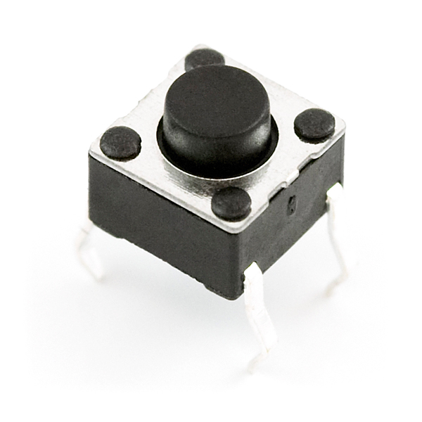
One of the major problems encountered when using push buttons and switches in digital electronics project is the problem of bouncing. When we press a button once it may register twice and when we press it four times, in a row, it may register just twice. This occurrence is due to a property of switches known as bounciness which is as a result of the physical property of the switches.
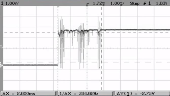
Contact bounce (also called chatter) is a common problem with mechanical switches and relays. Switch and relay contacts are usually made of springy metals so when a switch is pressed, its essentially two metal parts coming together and even though the connection may seem already made to the user, it may not happen immediately, as a matter of fact, it may make contact on one side – then both – and then the other side –, technically bouncing between in-contact and not-in-contact until it finally settles down. This result in a rapidly pulsed electric current instead of a clean transition from zero to full current as shown in the graph below.
One of the major problems encountered when using push buttons and switches in digital electronics project is the problem of bouncing. When we press a button once it may register twice and when we press it four times, in a row, for instance, it may register just twice. This occurrence is due to a property of switches known as bounciness which is as a result of the physical property of the switches.
Contact bounce (also called chatter) is a common problem with mechanical switches and relays. Switch and relay contacts are usually made of springy metals so when a switch is pressed, its essentially two metal parts coming together and even though the connection may seem already made to the user, it may not happen immediately, as a matter of fact, it may make contact on one side – then both – and then the other side –, technically bouncing between in-contact and not-in-contact until it finally settles down. This result in a rapidly pulsed electric current instead of a clean transition from zero to full current as shown in the graph below.
The effect of bouncing is usually unimportant in power circuits but causes problems in some analog and digital circuits that respond fast enough to misinterpret the on‑off pulses as a data stream and as such even though bouncing occurs within a millisecond time frame, the microcontroller often works at a faster speed and may fail or succeed to register the press of the switch due to the state of the bounce.
The effects of contact bounce can be eliminated (debounced) by use of mercury-wetted contacts, but these are now infrequently used because of the hazard of mercury release. Alternatively, contact circuits can be low-pass filtered to reduce or eliminate multiple pulses. In digital systems, multiple samples of the contact state can be taken or a time delay can be implemented in order for the contact bounce to settle before the contact input is used to control anything.
For today’s tutorial, we will be looking at how to remove the bounce effect in switches used for an Arduino project using software debounce method.
Required Components
The following components are required to build this project.
As usual, each of the components can be purchased by clicking on the link attached to them.
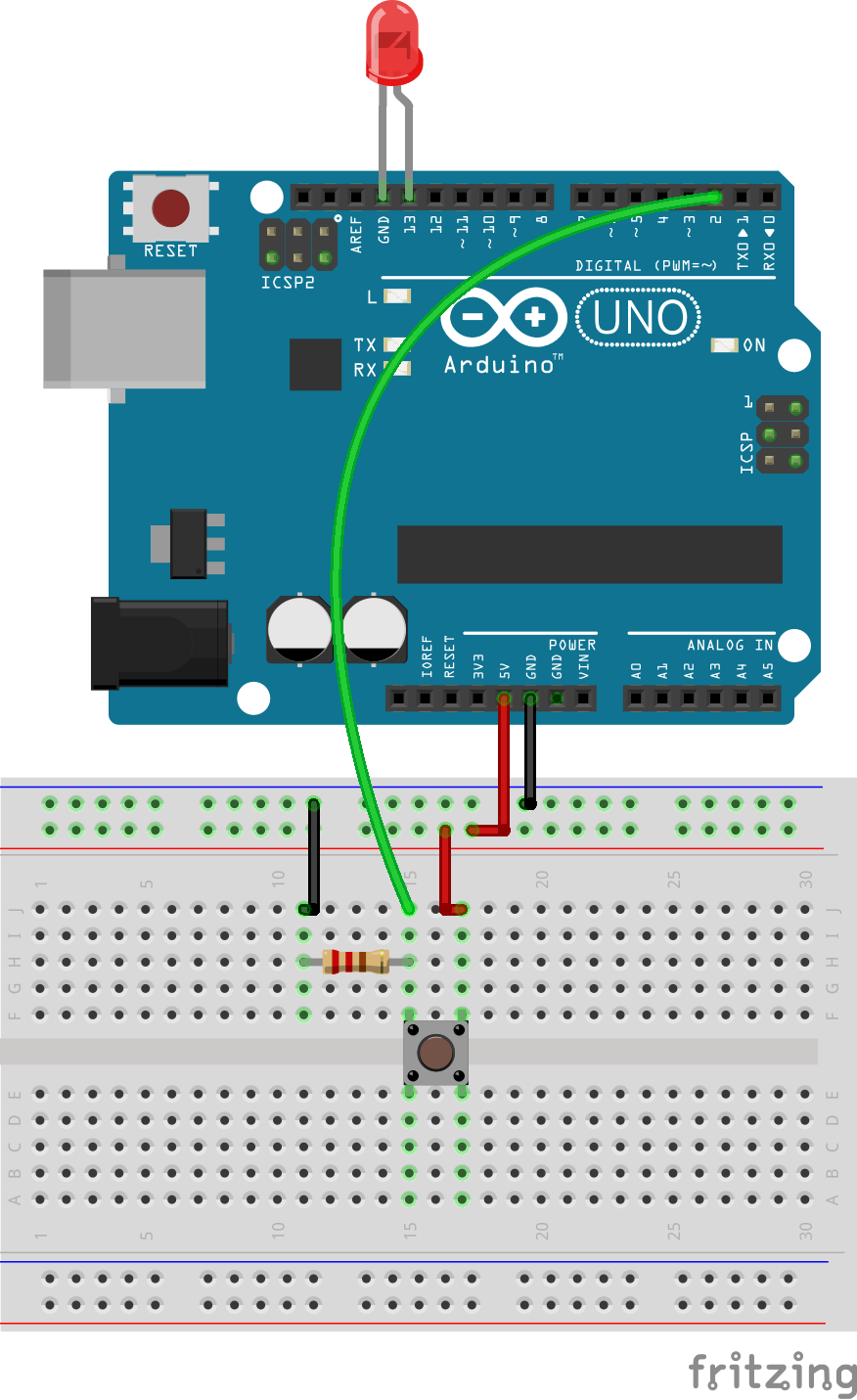
Schematics
The circuit for this project is fairly easy. Connect the components as shown in the schematics below.
Schematics
Check the connection once more to be sure everything is as it should be.
Code
Code for this project is a fairly simple one, we will not be using any library and our goal is to easily handle the debounce problem such that the when the switch is pressed it is read accurately by the microcontroller.
The first thing we do in the code is to declare the pins to which the LED and the pushbutton is connected to on the Arduino. We also declare variables which will be used to hold the state of the LED and the button.
    /////////////////////////////////////////////////////////////////
   //            Arduino Debounce Button     v1.01     //
  //         Get the latest version of the code here:            //
 //     http://educ8s.tv/arduino-button-debounce-tutorial       //
/////////////////////////////////////////////////////////////////

const int buttonPin = 2;
const int ledPin =  13;
int ledState = LOW;
boolean buttonState = LOW;

int pressed=0;
Next, we then move to the void setup function where we set the pin mode of the pin to which the LED and the push button are connected to on the Arduino.
With that done, we move into the void loop section. The actions performed within the void loop is heavily reliant on the debounce button function, which basically reads the state of a button then waits for a few ms after which it checks if the state is the same before it is registered.
The void loop uses this function to determine if a button was pressed and the number of times it has been pressed. When the number of times which the button has been pressed gets to 10, the LED is turned on.
The full code for the project is available below and can also be downloaded from the download section at the end of this tutorial.
/////////////////////////////////////////////////////////////////
// Arduino Weather Station Project #2 v1.01 //
// Get the latest version of the code here: //
// http://educ8s.tv/arduino-button-debounce-tutorial //
/////////////////////////////////////////////////////////////////
const int buttonPin = 2;
const int ledPin = 13;
int ledState = LOW;
boolean buttonState = LOW;
int pressed=0;
void setup() {
  pinMode(ledPin, OUTPUT);
  pinMode(buttonPin, INPUT);
}
void loop() {
if(debounceButton(buttonState) == HIGH && buttonState == LOW)
{
pressed++;
buttonState = HIGH;
}
else if(debounceButton(buttonState) == LOW && buttonState == HIGH)
{
buttonState = LOW;
}
if(pressed == 10)
{
digitalWrite(ledPin,HIGH);
}
}
boolean debounceButton(boolean state)
{
  boolean stateNow = digitalRead(buttonPin);
  if(state!=stateNow)
  {
    delay(10);
    stateNow = digitalRead(buttonPin);
  }
  return stateNow;

}
Demo
Copy the code, paste in the Arduino IDE and upload to your Arduino board. With the circuit setup as shown in the image below, you should see the LED come on after 10 button press.
With this, we can now build more reliable pushbutton/switch based projects.
That’s it for this tutorial guys, As usual, let me know if you have any questions or comments via the comment section.
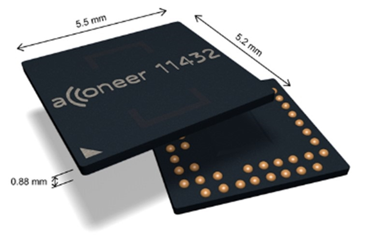
Acconeer’s A111 radar sensor is based on a unique patented technology enabling millimeter accuracy with very low power consumption
The Acconeer A111 is a low power, high precision 60 GHz pulsed SRD radar sensor with a footprint of 29 mm2, delivered in one chip system in package (SiP) solution with embedded RF and antenna. The small size and the low power consumption make it suitable for integration into any mobile or portable battery driven device.
The A111 radar sensor is based on a unique patented technology enabling millimeter accuracy with very low power consumption. The 60 GHz unlicensed ISM band provides robustness not compromised by any natural source of interference, such as noise, dust, color, direct or indirect light, and easy integration with no need of an aperture. The A111 radar sensor detects multiple objects at close range with single measurements as well as continuous sweeps set to any frequency rate up to 1500 Hz. Additionally, the unique characteristics of the radar sensor enable material recognition and motion detection for advanced sensing applications.
Features
Millimeter accuracy – distance mm accuracy for one or multiple objects
Movement and speed measurement – continuous measurements up to 1500 Hz
Material identification – distinguish between materials with different dielectric constant
Microwatt – enables integration into any battery driven device
Optimized integration – small one chip solution with embedded RF and antenna solution that requires no need for aperture
Robustness – not compromised by any natural source of interference, such as noise, dust, color, direct or indirect light
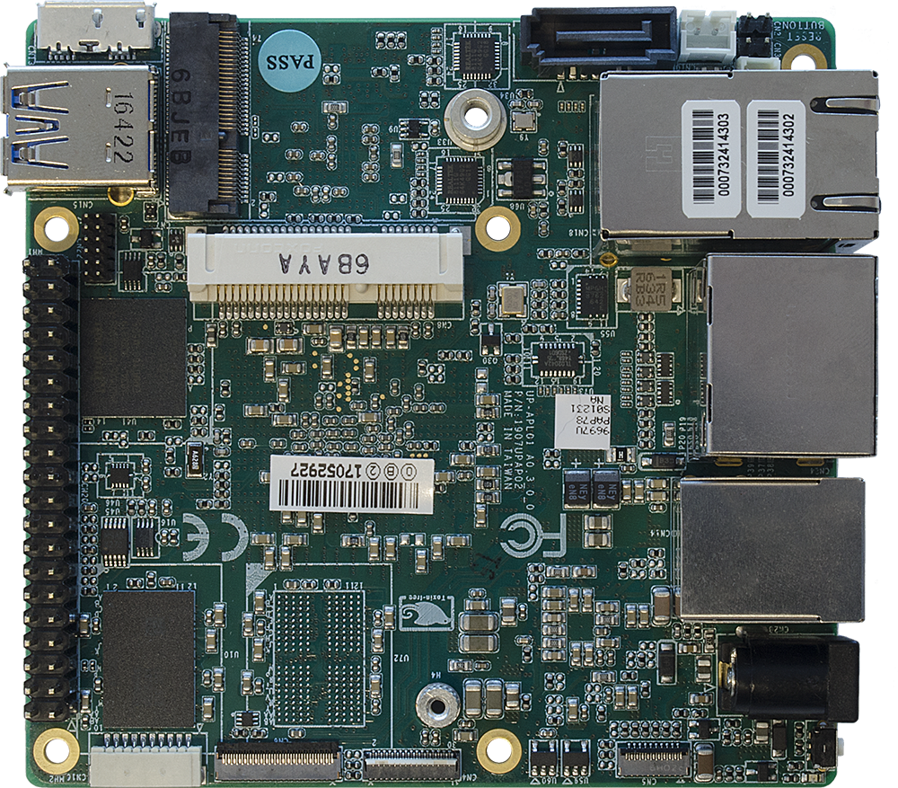
The UP Squared maker board, developed by Aaeon, creates custom-built IoT applications. The advanced maker board has low power consumption and high performance specifications.
UP Squared supports a range of operating systems including Ubuntu, Android 7.1, and Windows 10 IOT Core, which gives access to Microsoft app templates and code editors. Aaeon has also partnered with Intel to produce the UP Squared Grove IoT development kit, which includes components to custom-build IoT applications, such as sensors, buttons and a screen.
Powered by Intel Atom E3900 series, Intel Pentium N4200, or Intel Celeron N3350 processors (formerly codenamed Apollo Lake), UP Squared boasts two, four and eight Gbyte of LPDDR4 memory and up to 128Gbyte of eMMC storage. The board also houses an Intel Gen9 GPU, which supports 4K codecs. Expansion is via a 40-pin GPIO, a 60-pin EXHAT connector, or through SATA3, PCIe, and M.2 ports. The board also features multiple USB ports and CSI, HDMI, DP, and eDP interfaces.
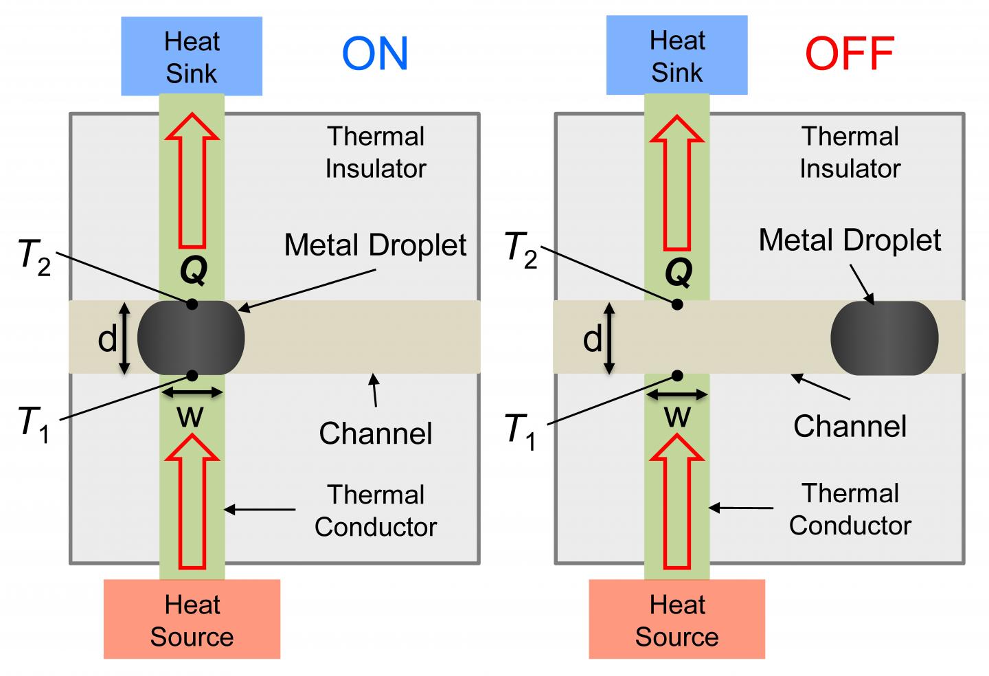
Schematic of the thermal switch showing the (a) ON-state with the liquid metal droplet bridging the heat source and sink and (b) OFF-state with liquid metal removed from the channel. (c) Side view image of the fabricated thermal switch device. (d) The ON and OFF thermal resistance circuits based on a 1-D heat transfer model.
A switch is a fundamental part of most electrical and mechanical devices; mechanical switches can be used to select gears in a car’s transmission or used to unlock a door; electrical switches can turn the lights in a room on and off; semiconductor uses to route logic signals within a circuit or control bigger devices. But what about heat flows? Can we possibly control the route of heat in a device? A Thermal Switch? Well, a thermal switch is an electromechanical device which opens and closes contacts to control the flow of electrical current in response to temperature change. A Thermal switch controls the flow of current concerning the temperature change, but this doesn’t actually control the flow of heat.
Heat flow is very important to engineers, and the heat movement in a device can profoundly affect the system performance and reliability especially in an electronics system. Engineers have long desired a switch to control heat flows, but many challenges exist in the creation of such a switch. Researchers from the College of Engineering at the University of Illinois at Urbana-Champaign have developed a new technology that allows users to turn heat flows “on” or “off.” This is a great development and it’s going to impact on future electronics systems.
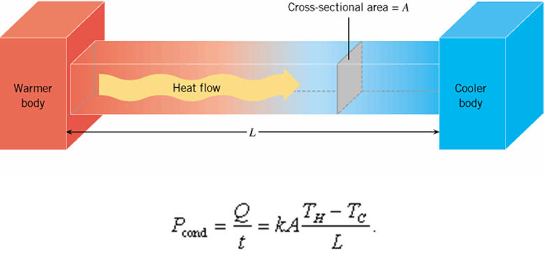
Heat Flow from Hot to Cool Region
“Heat flows occurs whenever you have a region on higher temperature near a region of lower temperature. In order to control the heat flow, the team engineered a specific heat flow path between the hot region and cold region and then created a way to break the heat flow path when desired” claims William King, the project co-leader and a professor at the department of mechanical science and engineering.
This technology became possible based on the principle of the “motion of a liquid metal droplet,” adds Nenad Miljkovic, assistant professor in the same department who also served as a project co-leader. “The metal droplet can be positioned to connect a heat flow path, or moved away from the heat flow path to limit the heat flow.”
The team demonstrated the technology in a system modeled after modern electronic systems, giving the potential of being deployed to our everyday devices. On one side of the switch was a heat source representing the power electronics component; on the other, liquid cooling for heat removal. When the heat switch was on, the team managed to extract heat at more than 10 W/cm2, but as soon as the heat flow was turned off, they saw a drop by nearly 100X.
According to King, the next step for the research will be to integrate the switch with power electronics on a circuit board. A working prototype will be produced later this year. The research was published in a recent edition of the journal Applied Physics Letters.