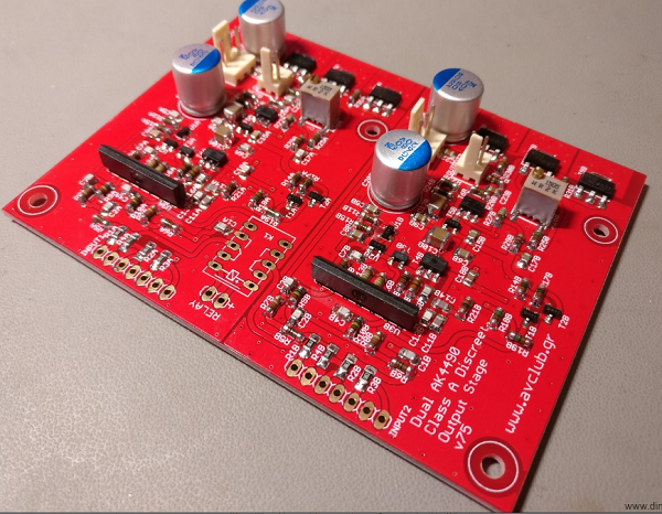
Following up on Part 2, it’s time to talk about the output stage. This output stage is the brainchild of my friend Kostas, all I did was lay out the PCB. It is a fully discreet single-ended class-A output stage, outputting ~2.4V RMS.
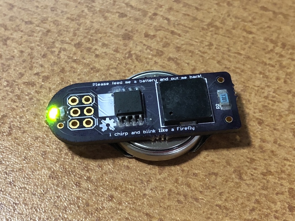
Here’s a tiny pcb that produces an annoying sound using a piezo buzzer and a ATtiny13 microcontroller.
It uses an LED, piezo buzzer, ATTINY13 Atmel microcontroller, a very small amount of Arduino code, and a coin cell battery that should last about a week.
Battery life could be improved, with longer sleep times. The device has but one function: sleep, then wake up periodically and blink and chirp, then go back to sleep.
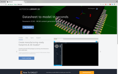
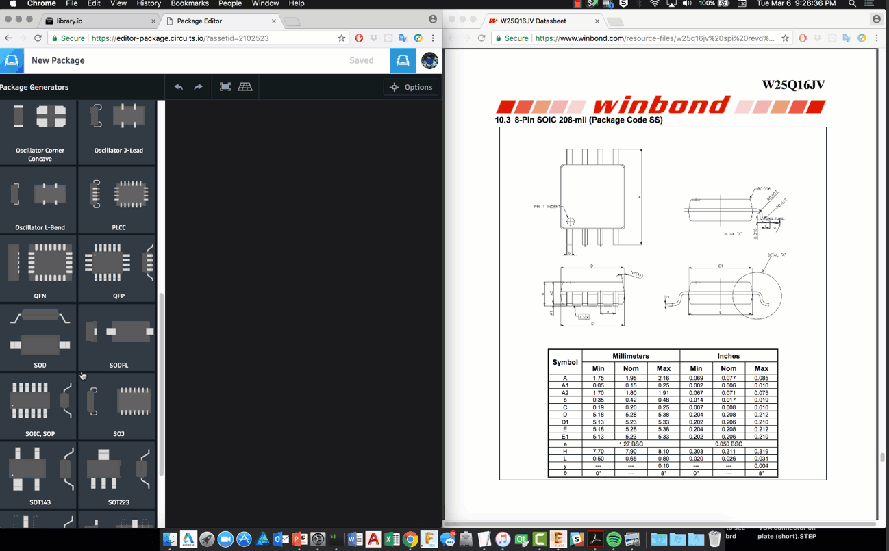
Today we’re proud to announce the release of EAGLE 8.7 and what is quite possibly one of the biggest releases we’ve had to-date, this time focused (largely) on libraries and library development (and what that means for 3D modeling of your finished PCB)! But before we get into it, let me share a thought —
As some of you know, most of us on the EAGLE team use the SW (imagine that!). In fact, it’s the overwhelming majority in development, mktg, leadership, support, etc. who not only use it, but we’ve run workshops, taught university courses with it, etc. And it’s from the experience of talking with you and having to explain many of the more idiosyncratic things either in EAGLE or in ECAD in general, that we’d decided we needed to take a shot at addressing the component creation process. Our goal being to reduce or eliminate one of the slowest, most non-value added processes in your workflow. (This is the stuff that really slows you down and only gets harder as the parts get more sophisticated.)
That being said, this is only part of our ongoing efforts to make library development and the problems with quick, quality component creation faced by so many users (whether professionals or hobbyists or students) a thing of the past. It’s also the first step in treating ECAD parts and their MCAD equivalents as a single component creation process which shouldn’t be decoupled (after all, it’s the same datasheet whether you’re making parts in EAGLE or in Fusion360).
EAGLE 8.7 – Parametric 2D & 3D model generation, library.io, more! – [Link]
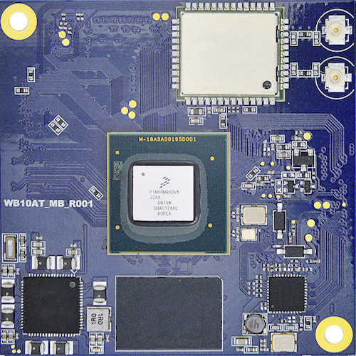
Last year (2017), NXP announced its new applications processors, the i.MX 8 series. The i.MX 8M family of applications processors based on Arm® Cortex®-A53 and Cortex-M4 cores provide industry-leading audio, voice and video processing for applications that scale from consumer home audio to industrial building automation and mobile computers. NXP announced a select group of partners that have been engaged in the development of an ecosystem for the i.MX 8M family processor. Taiwan based Innocomm Mobile Technology was one of those selected partners among others and have announced their NXP i.MX 8M quad-core system-on-module – called WB10 with wireless and wired connectivity options.
Innocomm WB10
Innocomm WB10 is a next generation Wireless System-on-Module powered by the NXP i.MX 8M SoC. It offered advanced video processing capabilities and designed for application in the areas of internet audio, home entertainment, smart speakers among many others. With inbuilt Wi-Fi, Bluetooth and Ethernet connectivity options, the WB10 can quickly find applications in the trending areas of Internet of Things (IoT) and Industrial applications.
The WB10 is a small module and measured at just 50 x 50 mm. The WB10 module comes with only 2GB LPDDR4 RAM and an 8GB eMMC flash memory. It provides onboard support for WiFi 802.11 a/b/g/n/ac, Ethernet controller with MIMO 2 x 2 and Bluetooth 4.2. Apart from impressive connectivity options, you also get a host of other interfaces like – USB 3.0 host, USB 2.0 device, 2x I2C, 3x UART, GPIO, PWM, SPI, and PCIe interfaces.
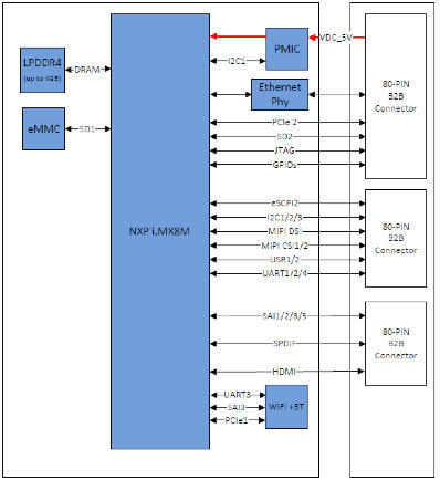
WB10 Block Diagram
The WB10 has an impressive audio and video interfaces with is Media I/O expressed via three 80-pin connectors that include an HDMI 2.0a supporting 4K and HDR, as well as MIPI-DSI, 2x MIPI-CSI, SPDIF Rx/Tx, 4x SAI, and the high-end DSD512 audio interface.
The following are some of the SoM specifications:
Processor – NXP i.MX8M Quad, Cortex-A53 x 4 + M4
Display –
4K + HDR
HDMI 2.0a
MPI DSI
RAM – 2GB LPDDR4
Flash Memory – 8GB eMMC Flash
Connectivity –
Wi-Fi 802.11 a/b/g/n/ac
MIMO 2×2 / BT 4.2
Ethernet 10/100M/1Gbps
Audio –
SAI
SPDiF Rx/Tx
DSD512
Dimension – 50 x 50 mm
Others –
USB 3.0/2.0 Host
USB 2.0 Device
i2C
SPI
UART
GPIO
CSI
PWM
PCIe
80 pins x 3, board to board connectors
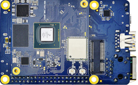
Carrier Board
Although no official software support has been provided, it is expected the SoM should support the usual Android and Linux BSPs as seen in most modules. A development carrier board is made available by the company to extend the SoM interfaces and will surely make development easier. The module connects to the carrier board through three 80-pin board-to-board connectors exposing many of the I/Os provided by the latest NXP processor.
At this point, no pricing or availability information is provided for the WB10. More information about the module can be found on the product page.
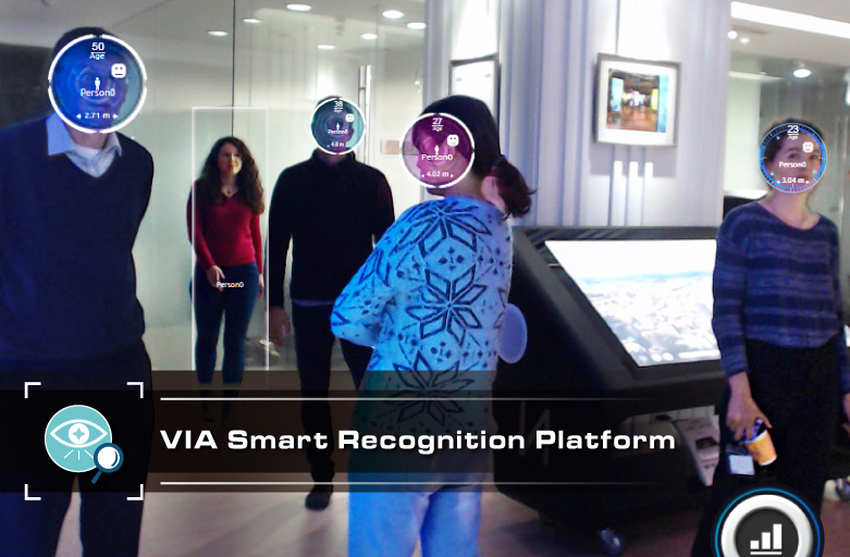
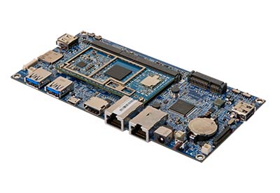
VIA Technologies, a global leader in the development of embedded platform and system solutions have announced its VIA Smart Recognition Platform powered by the Qualcomm Snapdragon 820 embedded platform. The VIA Recognition platform offers a robust development suite for Vision-based applications with the possibility of developing applications that can be used for detecting facial expression, faces, age and even the gender type of an individual. The VIA Technologies announced the VIA Smart Recognition Platform during the Embedded World 2018.
The Platform provides support for object and facial recognition, emotion detection, age and gender detection. Apart from that, the platform can be used for people counting and tracking. Applications for VIA Recognition Platform can be found in office buildings for staff access control and be delivering personalized adverts in retail signage kiosks. Others areas of note can be in traffic monitoring (counting of vehicles), security screening in airports and VIP places, payment authentication, surveillance and others. The platform’s advanced AI algorithm ensures speed and accuracy.
VIA_SOM-9X20_module Carrier Board
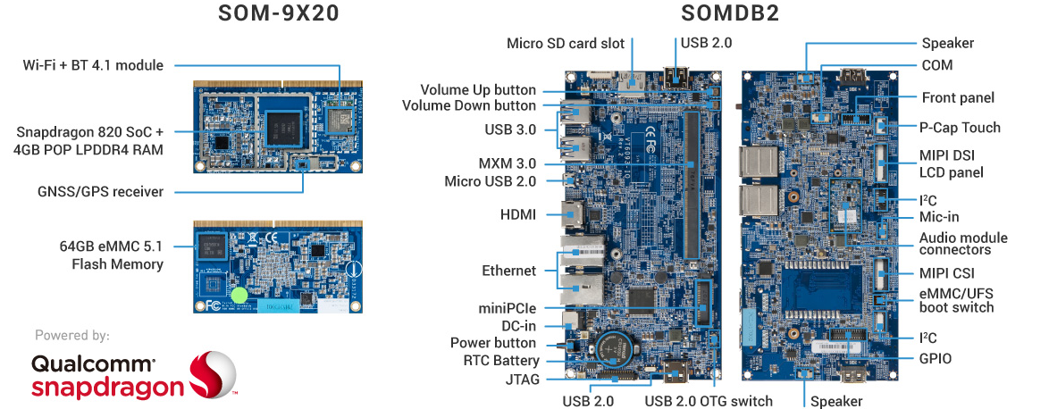
The VIA Smart Recognition platform is based on its VIA SOM-9×20 module powered by the Qualcomm Snapdragon 820 and coupled with a SOM-DB2 evaluation board. The significant difference with this current setup and the earlier SOM module is the pre-loaded facial and object recognition stack. The SOM-9×20 module features a Qualcomm Snapdragon 820 with 4x Cortex-A72-like cores Kryo cores, two of those run at 2.2GHz and the last two at 1.6GHz. Measuring at 82mm x 45mm, the module features a 64GB eMMc Flash memory, 4GB LPDDR4 SDRAM, a 624MHZ Adreno 530 GPU, and a Hexagon 680 DSP. It offers rich I/P and display interface through its MXM 3.0 314-pin connector including USB 3.0, USB 2.0, HDMI 2.0, SDIO, PCIe, MIPI CSI, MIPI DSI, and multi-function pins for UART, I2C, SPI, and GPIO. It comes with a wireless module that includes Wi-Fi 802.11 a/b/g/n/ac, Bluetooth 4.1 and a separate GPS/GNSS RF receiver with an antenna connector.
The carrier (SOM-DB2 expansion) I/O board is expected to help in accelerating system development. The board extends out the module interfaces, including 2x Ethernet 2x USB 3.0, micro-USB 2.0, HDMI, and a microSD. The VIA Smart Recognition Platform comes with a BSP that features Android 7.1.1 as well as the VIA Smart ETK (Embedded Tool Kit) comprising some APIs, including Watchdog Timer (WDT) for safeguarding against system crashes, GPIO access, RTC for auto-power on, and a sample app. A BSP supporting Linux Kernel 3.18.44 is also under development.
According to Richard Brown, VP International Marketing of VIA Technologies, “Computer vision technologies such as facial and object recognition are becoming a vital tool for boosting public safety and convenience everywhere from check-in counters and security screening in airports to self-service kiosks and payment authentication systems in supermarkets. The VIA Smart Recognition Platform speeds up the development and deployment of tailor-made systems that harness these cutting-edge technologies to deliver innovative new customer services and experiences.”
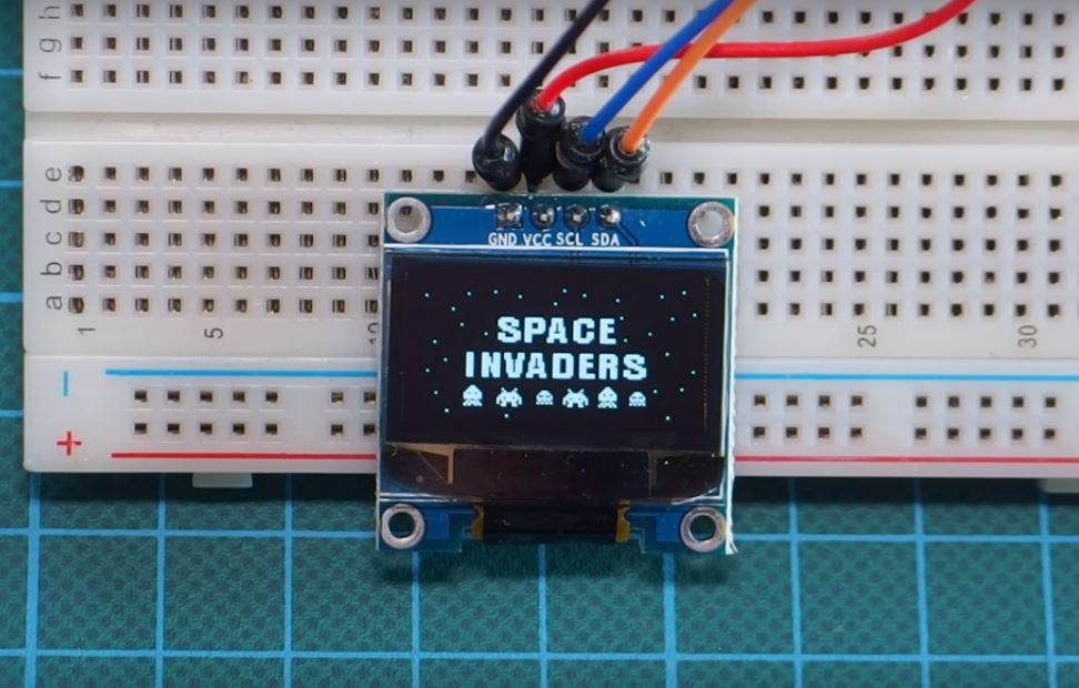
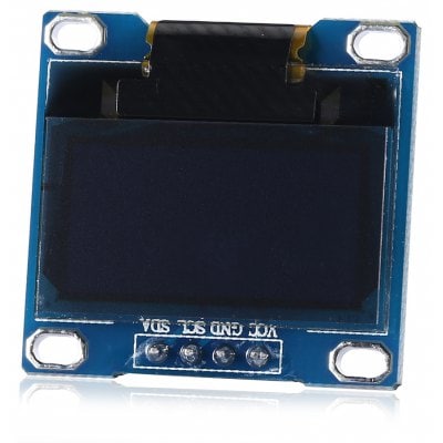
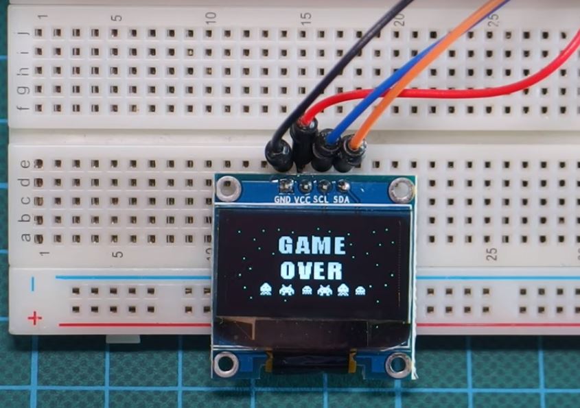
One thing we all always wish we could do when using any display is to load our own custom graphics, be it a logo, gif etc. In today’s tutorial we will show how to do just that on an OLED display using an Arduino.
OLED (organic light-emitting diode) display is a display based on light-emitting diode (LED) in which the emissive electroluminescent layer is a film of organic compound that emits light in response to an electric current. This layer of organic semiconductor is situated between two electrodes; typically, at least one of these electrodes is transparent. OLEDs are used to create digital displays in devices such as television screens, computer monitors, portable systems such as mobile phones, handheld game consoles, and PDAs. OLED displays do not require a backlight because they emit visible light and can thus, display deep black levels and be thinner and lighter than a liquid crystal display (LCD).
Displaying Customized Graphics on OLED display using Arduino – [Link]
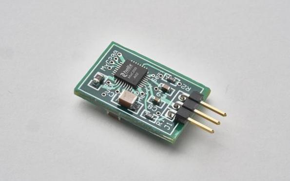
Fabless power semiconductor startup Helix Semiconductors has started mass production of its MxC200, a configurable high-efficiency 15W DC-DC power chip.
Previously known as the HS200, the MxC200 takes voltage input ranging from 12V to 48V and converts it to selectable lower voltages. For example, when configured as a 48V input to 12V output, the device offers greater than 97 percent peak efficiency and greater than 90 percent efficiency at full load. by Nick Flaherty @ eenewseurope.com
With the MxC200 and other MuxCapacitor-based products, Helix Semiconductors is answering the demand for more energy-efficient power ICs in the burgeoning AC-DC and DC-DC markets,” said Harold Blomquist, president and CEO of Helix Semiconductors. “The MxC200 features a unique three-stage process, each of which divides its input in half. Power can be pulled from any of its three outputs simultaneously up to 15W. The company’s MuxCapacitor technology enables the MxC200 to achieve unprecedented high efficiency and to stay nearly flat from full load down to 5 percent load.
Helix Semiconductors starts production of DC-DC power chip – [Link]
One thing we all always wish we could do when using any display is to load our own custom graphics, be it a logo, gif etc. In today’s tutorial we will show how to do just that on an OLED display using an Arduino.
OLED (organic light-emitting diode) display is a display based on light-emitting diode (LED) in which the emissive electroluminescent layer is a film of organic compound that emits light in response to an electric current. This layer of organic semiconductor is situated between two electrodes; typically, at least one of these electrodes is transparent. OLEDs are used to create digital displays in devices such as television screens, computer monitors, portable systems such as mobile phones, handheld game consoles, and PDAs. OLED displays do not require a backlight because they emit visible light and can thus, display deep black levels and be thinner and lighter than a liquid crystal display (LCD).
Displaying Custom Graphics on an OLED
We covered how to display text on the OLED display in one of our previous tutorials which can be found here.
Required Component
The following components are required to build this project;
As usual, the exact components used for this tutorial can be bought by following the link attached to each of them.
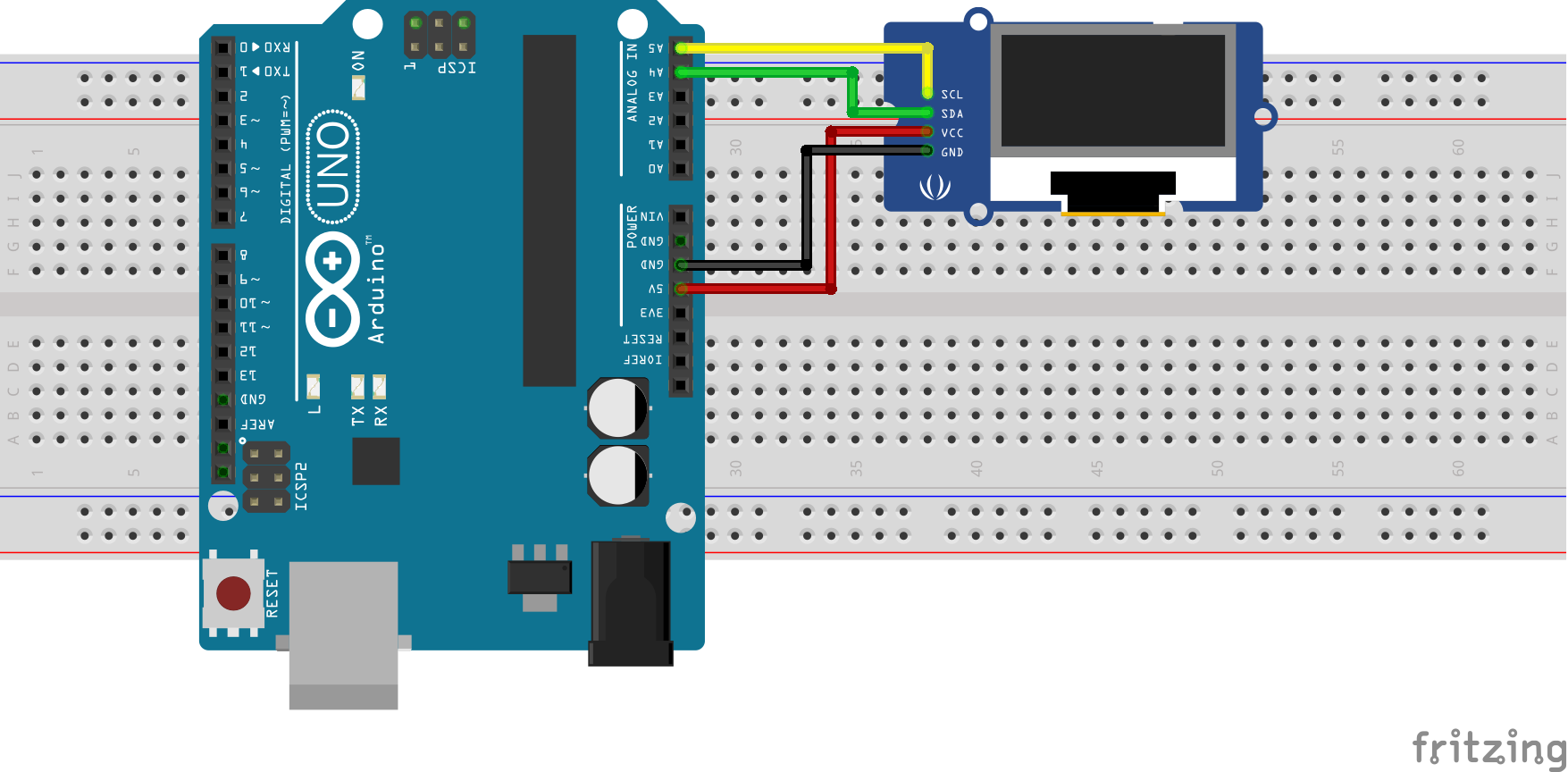
Schematics
The schematics for this project is a simple one as it involves just the connection between the OLED display and the Arduino. Connect them as shown in the Schematics below.
Schematics
For clarity, the pin connection between the Arduino and the OLED display is also described below.
OLED – ARDUINO
VCC - 5v
GND - GND
SCL - SCL
SDA - SDA
Creating the Graphics
After connecting the LCD to our Arduino, the next line of action is to prepare the graphics to be displayed.
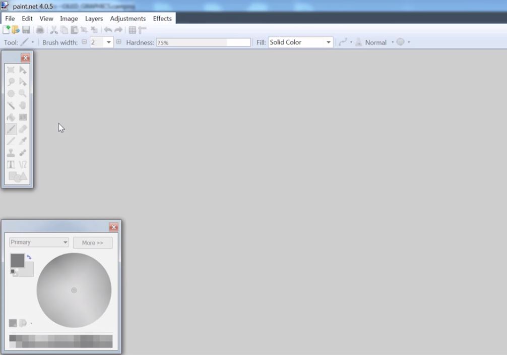
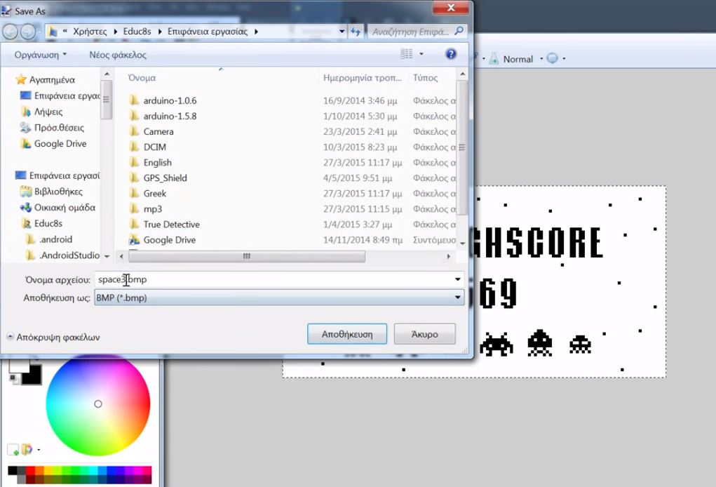
The graphics can be created/designed using tools like Microsoft paint, Corel draw, Paint.net or Adobe Photoshop. The important thing is to ensure the image is saved as a bitmap.
For the purpose of this tutorial, we will be using the paint.net tool. It is easy to use and can be downloaded from here.
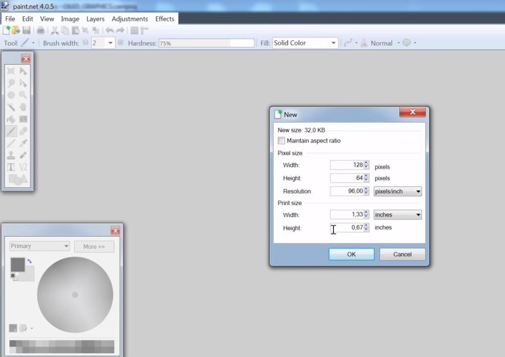
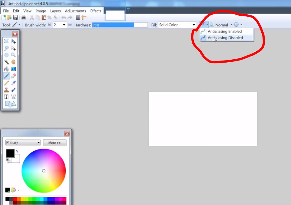
One thing that should be kept in mind while creating the graphics or logo is the canvass size. It’s important the canvass size is same as the screen, to ensure the designed graphics shows perfectly on the display. For our case, the canvass size is 128 x 64 as this is the resolution of our LCD.
It is also important to disable antialiasing when using the paint.net software and the graphics should be designed only in black and white as these are the only color schemes that work on the OLED display. Any other color used will not be visible on the display.
After creating the graphics save it as a bitmap image.
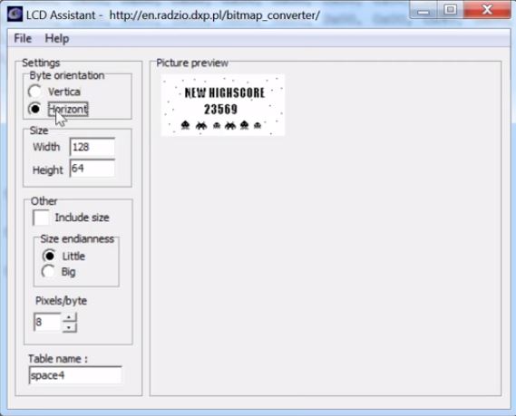
To load the graphics into our Arduino code, we will need to convert the bitmap image into byte arrays. To do this, we will use the LCD assistant software. LCD Assistant is a free and easy to use software that converts bitmap images into a data array which can then be used in C programming language based firmware for any micro-controller. The software can be downloaded here.
Load the bitmap image into the software as shown in the image below and save the output. It will return a data array which we will use later when writing the code, so ensure it is saved.
With our graphics converted to a byte array, we have all we need to proceed with the code.
Code
The code for this tutorial is fairly simple, to facilitate the communication with the OLED display, we will be using U8 graphics library for Arduino which can be downloaded from this website here. Unzip the code into your Arduino libraries folder and launch an instance of the Arduino IDE. The code, using the void draw function will basically be displaying the graphics represented by each of the byte arrays we specify, one after the other, with a delay in between to ensure the graphics stay long enough on the screen to be seen.
To implement this procedure, the first thing we do, as usual, is to include the libraries we will be using.
    /////////////////////////////////////////////////////////////////
   //      Arduino OLED Display Graphics Tutorial v1.00           //
  //       Get the latest version of the code here:              //
 //   http://educ8s.tv/arduino-oled-display-graphics-tutorial   //
/////////////////////////////////////////////////////////////////

#include "U8glib.h"

U8GLIB_SH1106_128X64 u8g(U8G_I2C_OPT_NO_ACK);	// Display which does not send ACK
In this code, we have three different byte arrays each of which represents different graphics. You can add your own byte array by copying the output of the LCD assistant software and pasting it into the code with a proper variable name following the format of the samples in the code.
The void draw function is the most important part of this project as it is in charge of drawing the graphics on the display. The function uses the u8g.drawBitmapP function from the U8 graphics library to draw the specified bitmap. The u8g.drawBitmapP function has five arguments; the first two are the x and y coordinates of the top left position on the screen where we want the graphics display to start from. The 3rd argument is the width of the bitmap image (128 in this case) divided by 8 while the 4th argument is the height of the bitmap image (64 in this case). The last argument is the variable name given to the byte array which represents the image to be displayed.
we leave the void setup function blank since it’s not necessary for this tutorial, but it must be included as its needed for the Arduino code to compile.
void setup(void) {
}
Next, we write the void loop() function. The void loop function for this project is fairly simple, all we need to do is call the void draw function to display a graphics and wait for few seconds before calling the function to display the next graphics.
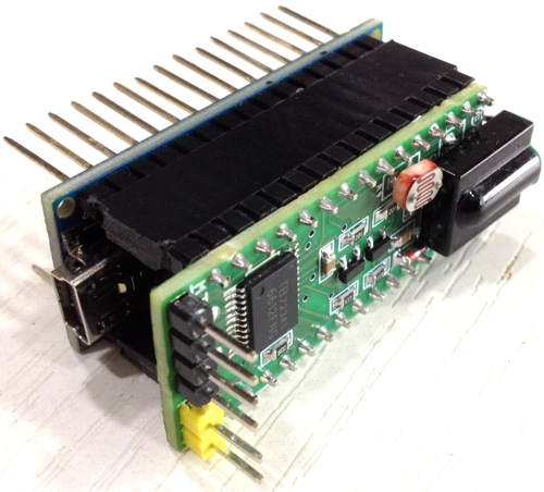
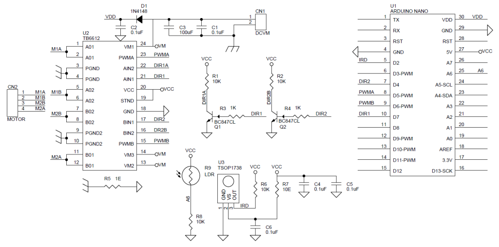
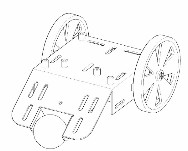
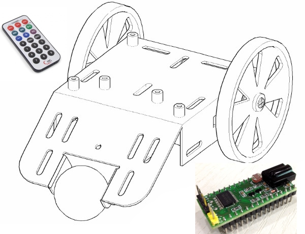
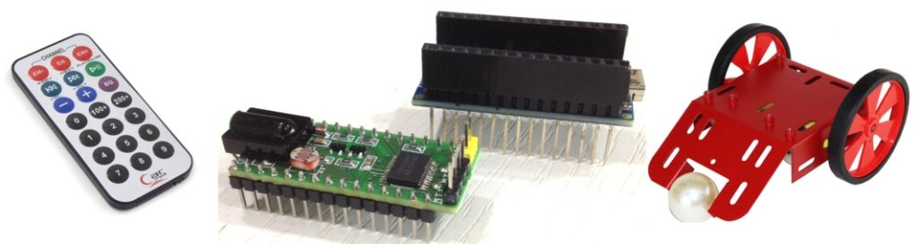
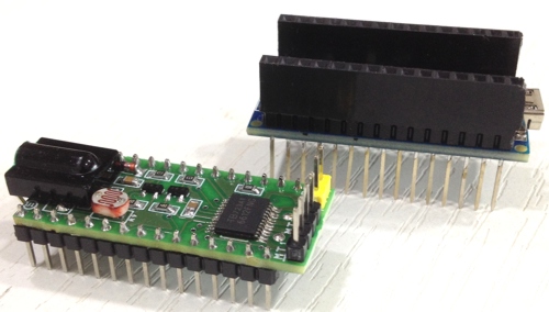
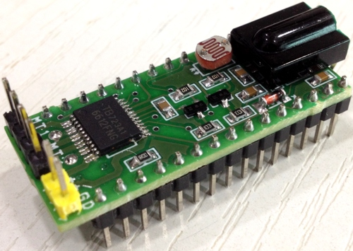
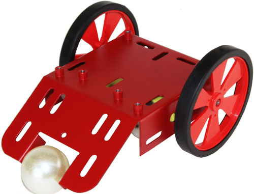
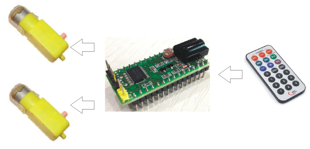
The Mini Infra-Red Remote Robot Controller shield for Arduino Nano is designed to drive mini mobile robots. Low voltage DC Motor controller interface allows Infrared wireless control of two DC motors, two PWM and 2 Direction signal outputs to drive two motors separately. TB6612 IC is the heart of the project. IC can handle constant current up to 1.2A, Supply 6-12V DC. One LDR connected to Analog pin A7 for application like light sensitive robot controller. Infrared receiver TSOP1738 used as IR receiver which is connected to Digital pin D2 of Arduino Nano. Nano D7-Direction Motor A, D4 Direction Motor B, D5 Motor A PWM signal, D6 Motor B PWM signal.
Mini Infra-Red Remote Robot Controller Shield For Arduino Nano – [Link]
The Mini Infra-Red Remote Robot Controller shield for Arduino Nano is designed to drive mini mobile robots. Low voltage DC Motor controller interface allows Infrared wireless control of two DC motors, two PWM and 2 Direction signal outputs to drive two motors separately. TB6612 IC is the heart of the project. IC can handle constant current up to 1.2A, Supply 6-12V DC. One LDR connected to Analog pin A7 for application like light sensitive robot controller. Infrared receiver TSOP1738 used as IR receiver which is connected to Digital pin D2 of Arduino Nano. Nano D7-Direction Motor A, D4 Direction Motor B, D5 Motor A PWM signal, D6 Motor B PWM signal.
Arduino Nano Pin Configuration
DIGITAL PIN D2 – TSOP1738 INFRA RED RECIVER
DIGITAL PIN D7-DIRECTION PIN OF TB6612 MOTOR-A
DIGITAL PIN D4-DIRECTION PIN OF TB6612 MOTOR-B
DIGITAL PIN D5-PWM PIN OF TB6612 MOTOR-A (MOTOR-1)
DIGITAL PIN D6-PWM PIN OF TB6612 MOTOR-B (MOTOR -2)