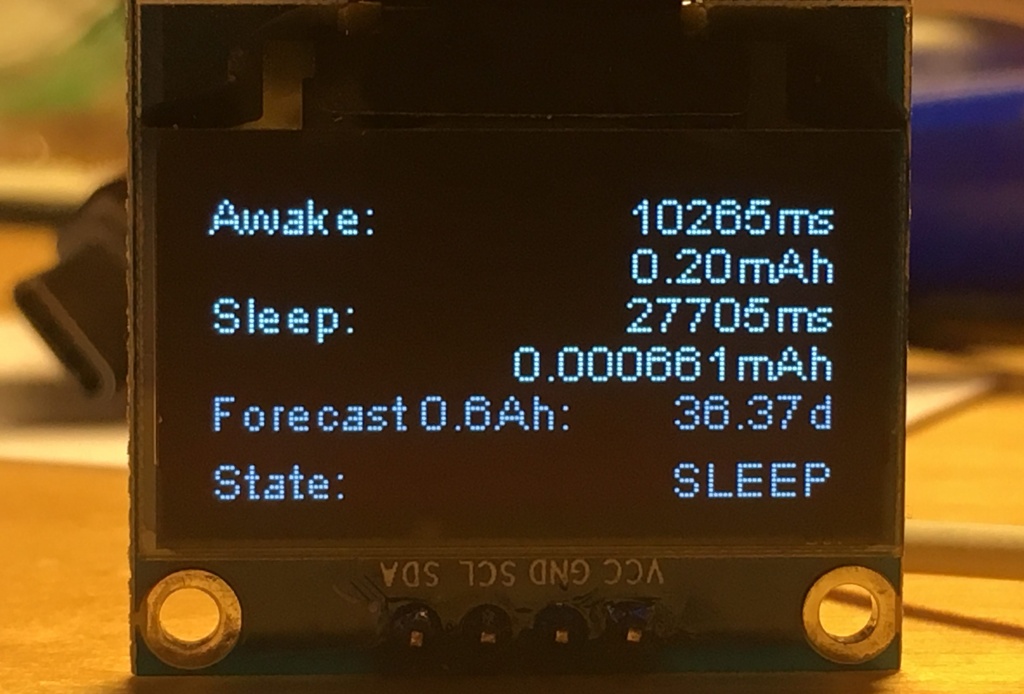
In this post I’m going to show you how you can monitor the power consumption of your battery driven (ESP8266/ ESP32) device. Measuring the power consumption over a full activity/ sleep cycle is the precondition to optimize your code for a longer battery runtime. Only with a reliable tool you can decide which code changes lead to less consumption. In a later post we’ll look at some tweaks we can apply to the code to get a few more days out of the battery.
Adding components from Ambiq Micro and Talent Highland, Fujitsu Electronics Europe has increased its Bluetooth Low Energy portfolio.
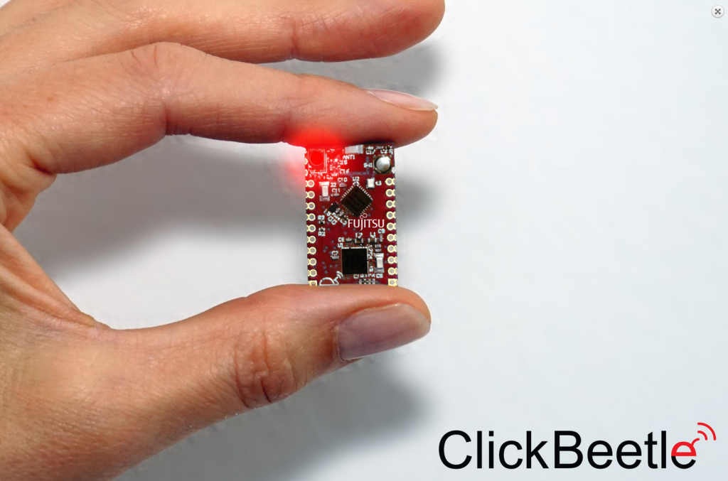
The additional products offer customers high integration, low power consumption and flexibility, says Fujitsu Electronics Europe (FEE), and it has produced the ClickBeetle reference platform (pictured) to facilitate the integration of Bluetooth Low Energy products into applications.
Ambiq Micro’s Bluetooth Low Energy components make Bluetooth Low Energy applications more powerful and efficient, claims FEE. The Cortex M4 in Apollo 2 operates at up to 48MHz at only 10-microA/MHz with a deep-sleep current of two micro A. Apollo 1 operates at up to 24MHz at 34-micro A/MHz and has a deep-sleep current of 143-nanoA. Additional components offer the possibility of lowering the deep-sleep current to 22-nanoA. Depending on the requirements, Ambiq Micro offers different bundle packages to combine its Apollo 1 and Apollo 2 microcontrollers or real time clocks with an EM9304 BLE communication chip. Combinations of microcontroller and Bluetooth Low Energy chips are suitable for high-performance applications, while combinations of real time clocks and Bluetooth Low Energy are ideal for cost-sensitive Bluetooth Low Energy beacons. Packages range from BGA, CSP and QFN packages. For very small applications, Ambiq Micro also offers a SoC that combines the Apollo 2 microcontroller and EM9304 BLE in a 4.0 x 4.0mm LGA package with 64 pins.
Customers who would like to integrate Bluetooth Low Energy further can also use a Talent Highland SIP. Components such as a DA14580 with ARM Cortex M0 16 MHz and 42kbyte RAM, 1Mbit SPI flash, crystals, passive components and antenna are bundled in a package measuring only 7.0 x 7.0mm. Thanks to the internal DC/DC converter, the small module also supports three and 1.5V batteries. Depending on the requirements, FEE customers can also create their own package with their own components.
FEE offers its reference platform, ClickBeetle, for application-oriented evaluation and development. It measures just 16 x 26mm and uses a hardware-independent fixed pin layout, making it easy to replace and evaluate Bluetooth Low Energy components, says Fujitsu.
RGB Matrix displays are a great way adding interactions to a project and displaying objects in a 2D space. RGB LED matrices can be used as a display for playing games, display animations, watch movies, display sensor data, and much more can be the done with these big and beautiful LED displays. Of course, RGB Matric display is best controlled with a high-speed processor like FPGA, but you can still use the Raspberry Pi to control them also. Most of the things (if not everything) the Raspberry Pi can output to a monitor can be displayed on LED matrices display.
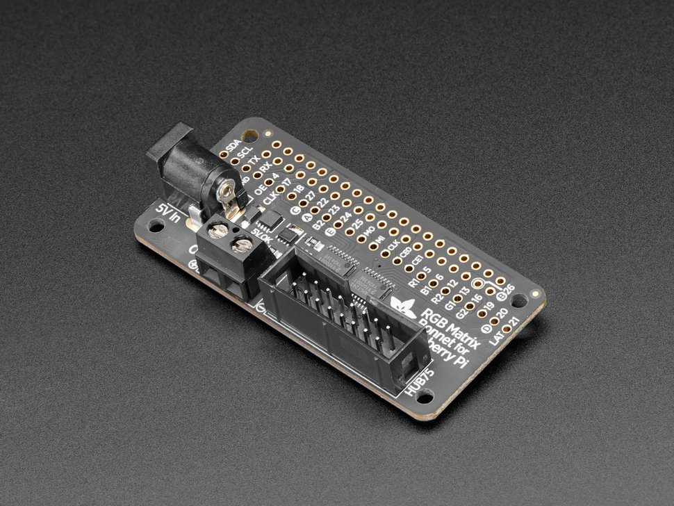
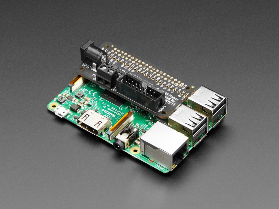
Adafruit RGB Matrix Bonnet
Adafruit has announced the arrival of its RGB Matrix control board for the Raspberry Pi called the Adafruit RGB Matrix Bonnet. The Matrix Bonnet allows one to use the popular Raspberry Pi to control RGB Matrics displays to create a colorful scrolling display, view short videos, and for showing animations. The matrix board plugs easily into the Pi and works on any Raspberry Pi with a 40-pin GPIO header – Zero, Zero W/WH, Model A+, B+, Pi 2 and Pi 3. If you still use the old model 26-pin boards like the Model A or Model B, unfortunately, the bonnet can’t plug into them, and you will need the newer boards.
Adafruit RGB Bonnet
The Matrix control board can work with any 16 x 32, 32 x 32 or 32 x 64 RGB LED Matrices with HUB75 connections. It is also possible to use the bonnet board with 64 x 64 matrix display by doing some hardware hacking – soldering a small jumper on the PCB. And yes, you can get more displays by chaining multiple matrices together for a bigger display. Chaining numerous displays together will also cause some extra workload on the Raspberry Pi itself.
The bonnet board is quite rugged and comes with an inbuilt power protection circuitry to protect the board from short circuits, over and under-voltages. It has onboard level shifters to convert the RasPi’s 3.3V to 5.0V logic which will create a glitch-free matrix driving for 5V logic RGB Matrix display. It also comes fully assembled and no need for any extra soldering work.
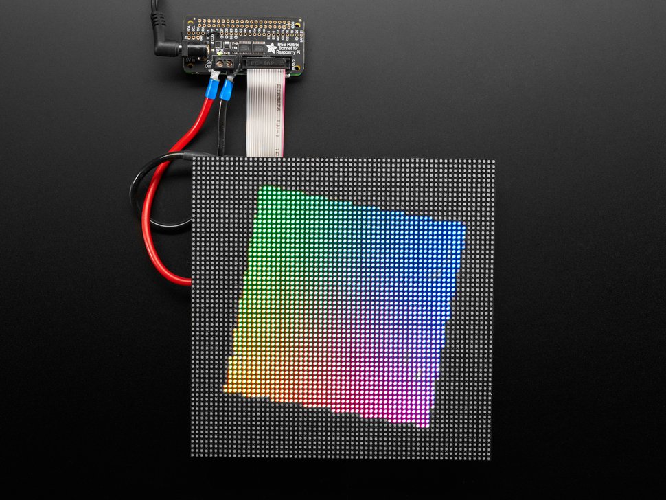
The main advantage of the Adafruit RGB Matrix bonnet is that it will allow you to interact with RGB matrix display while avoiding the complicated wiring involved with connecting those displays.
Adafruit Bonnet connected to a Pi
The RGB Matrix Bonnet for Raspberry Pi is now available to purchase priced at $14.95 and can be bought on the Adafruit online store. The bonnet works with only HUB75 type RGB matrices and not the likes of NeoPixel, DotStar or other ‘addressable’ LEDs. For more information about using the bonnet, check out the product page on Adafruit.
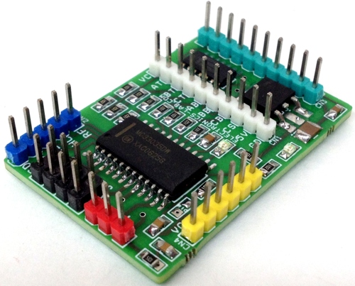
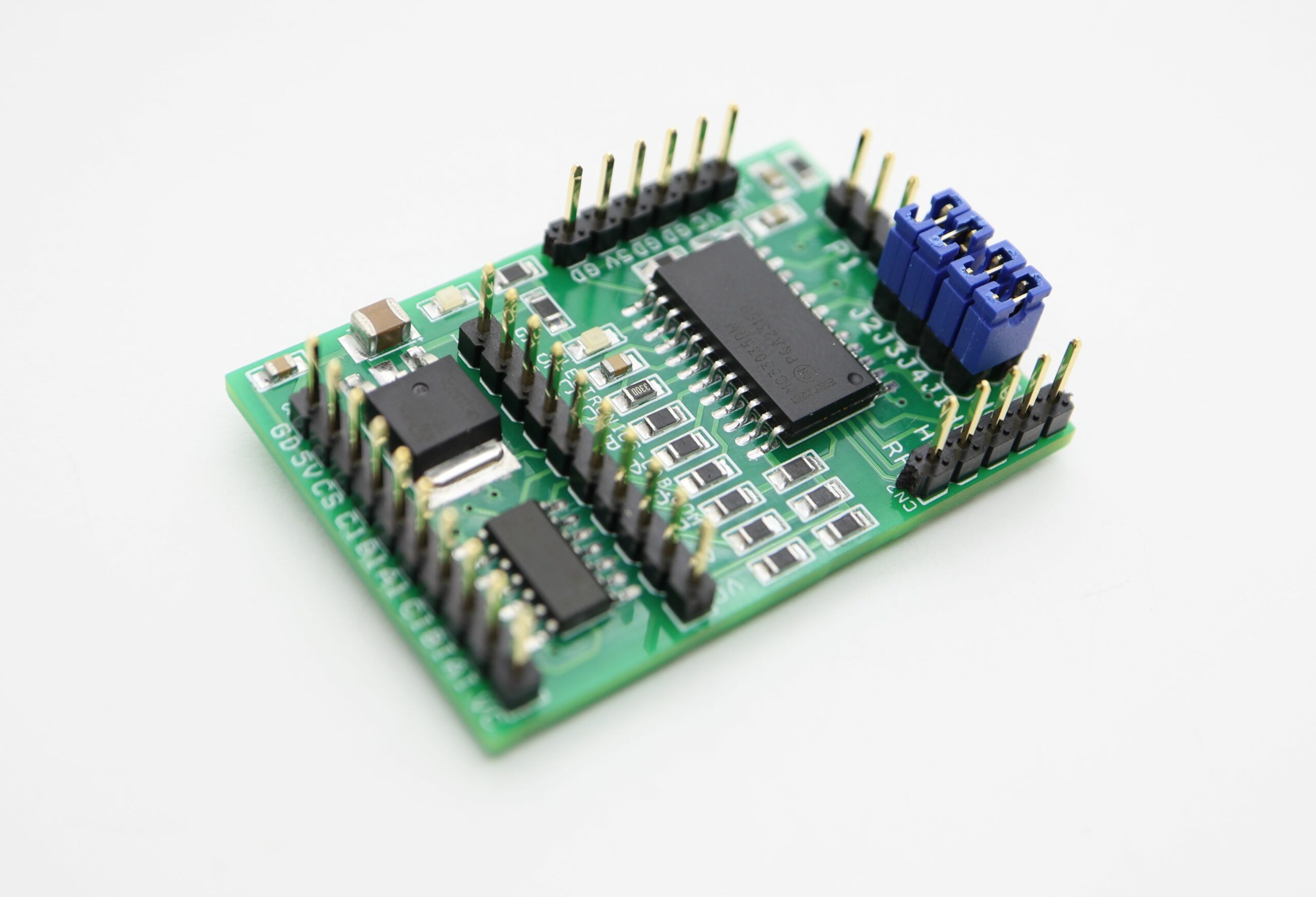
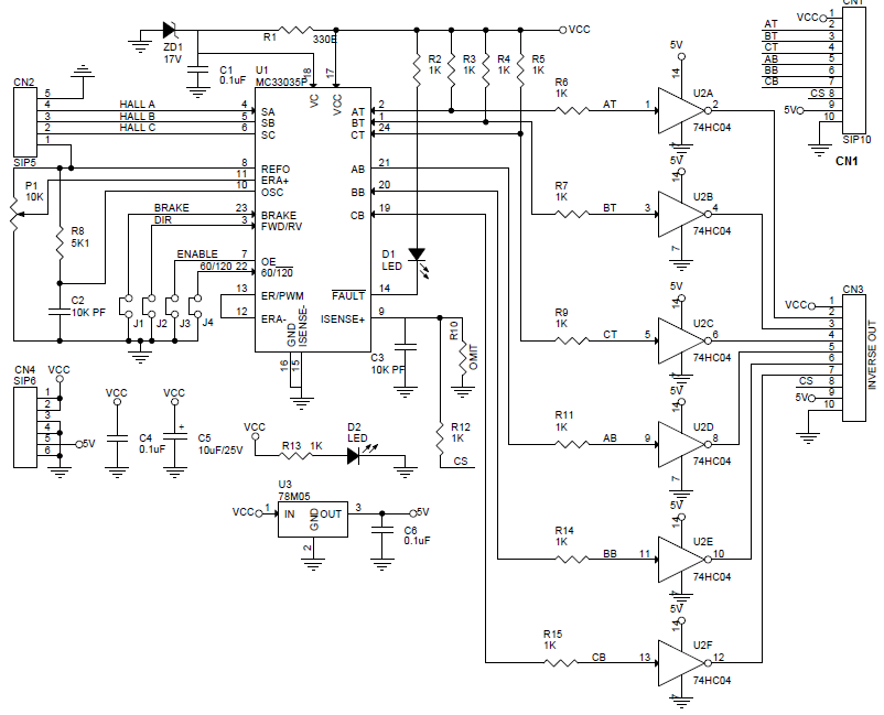
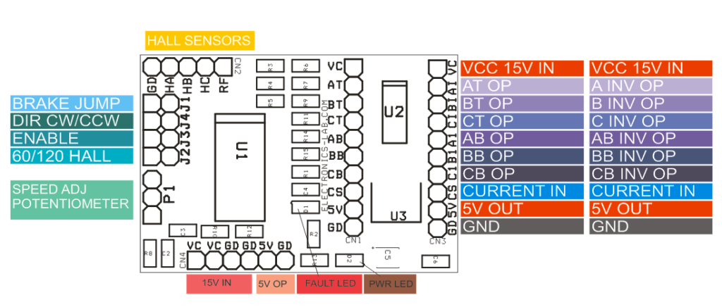
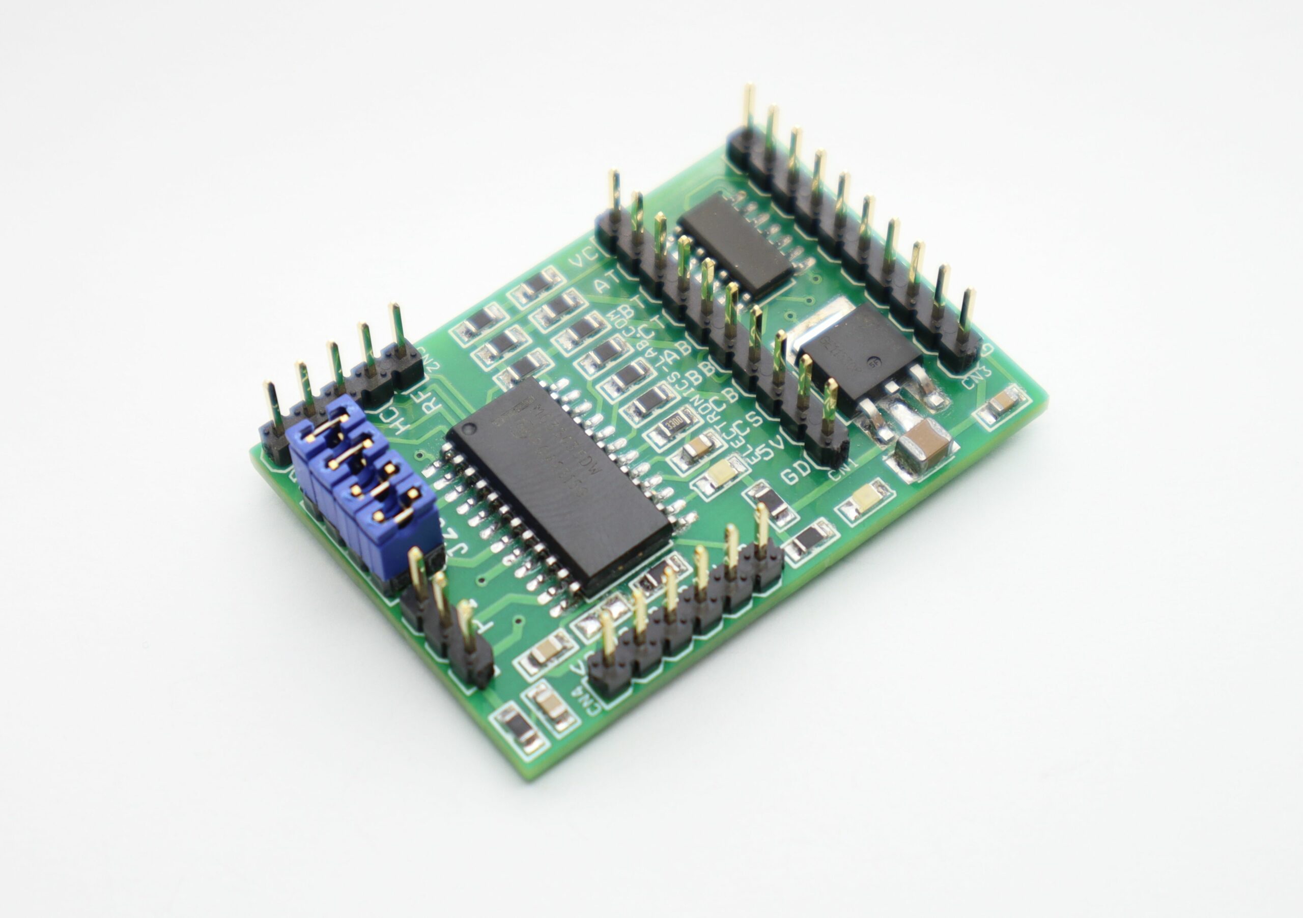
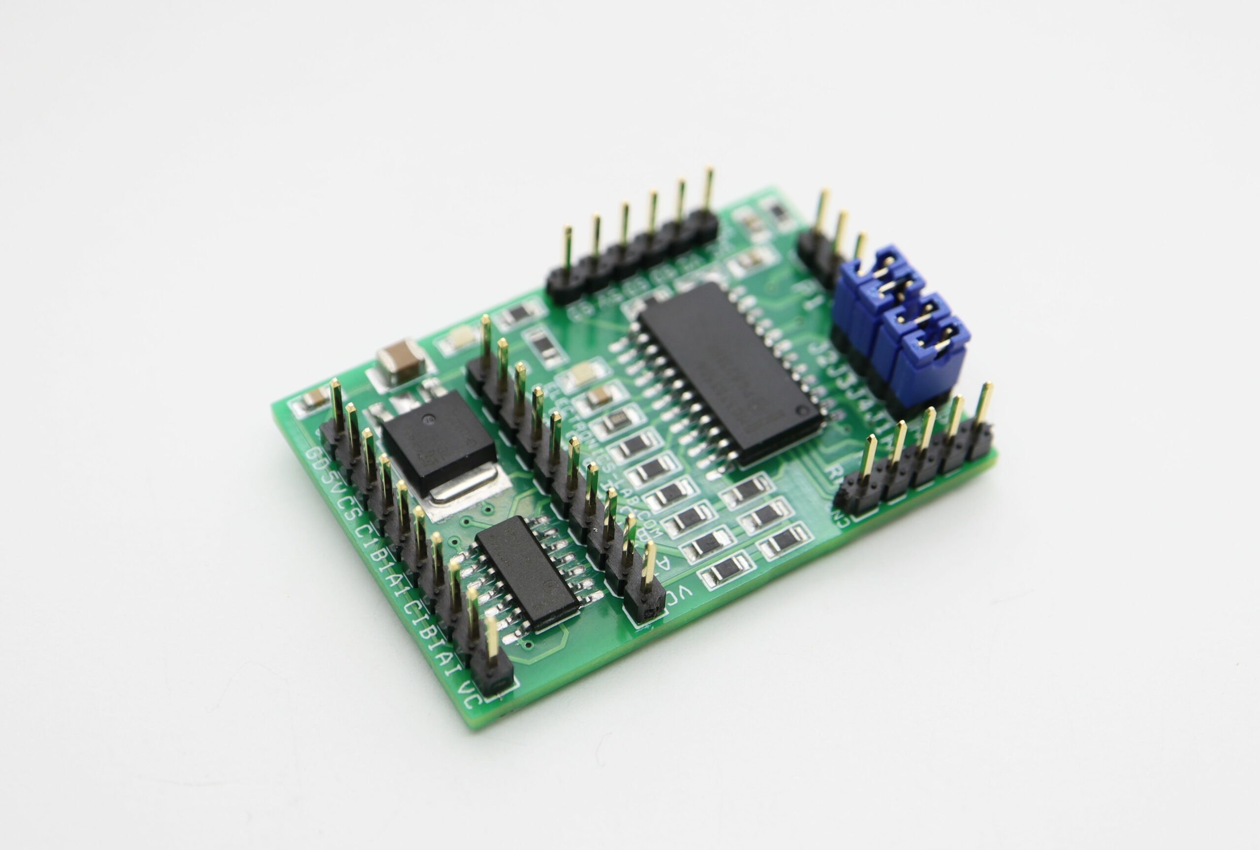
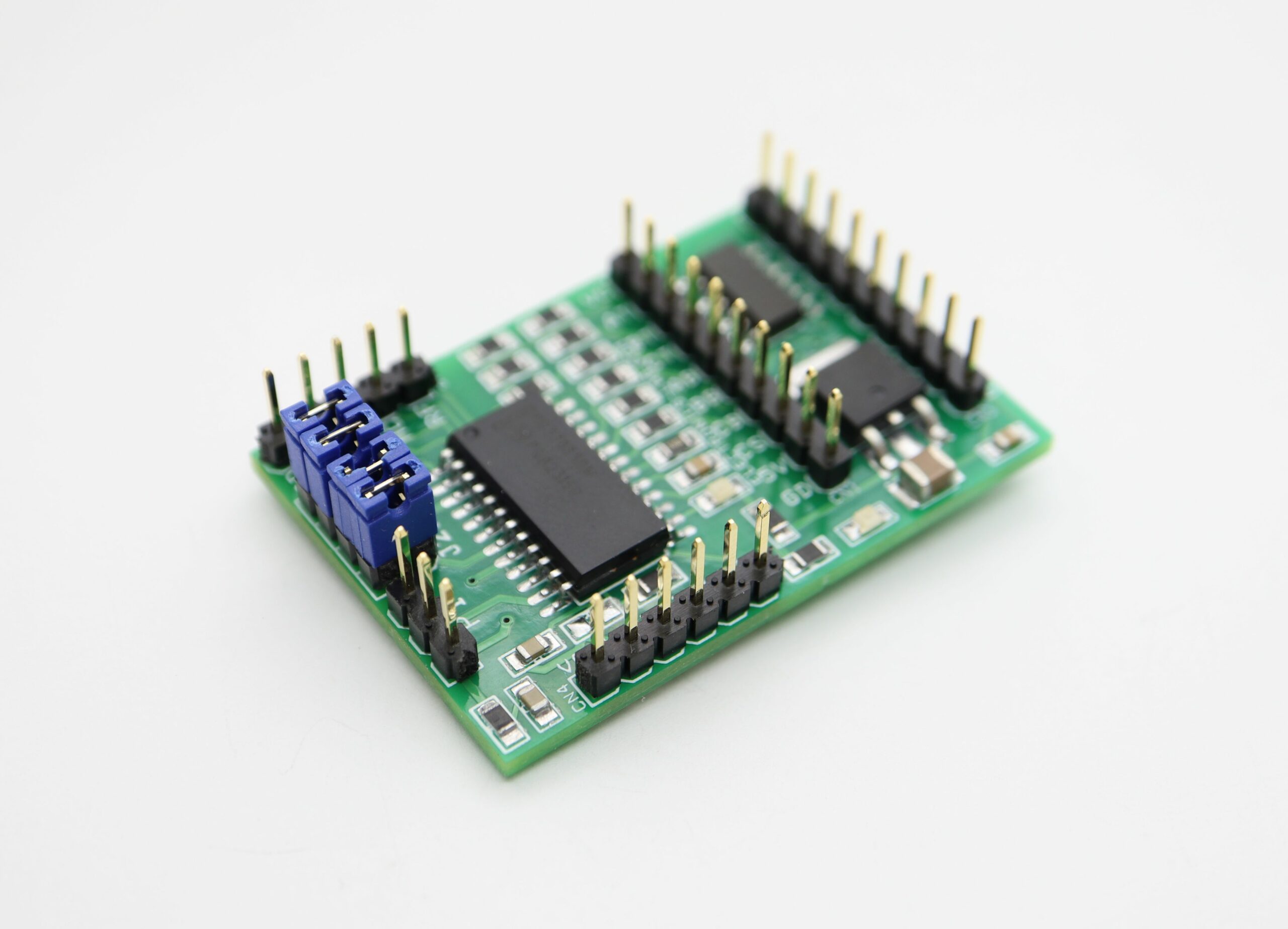
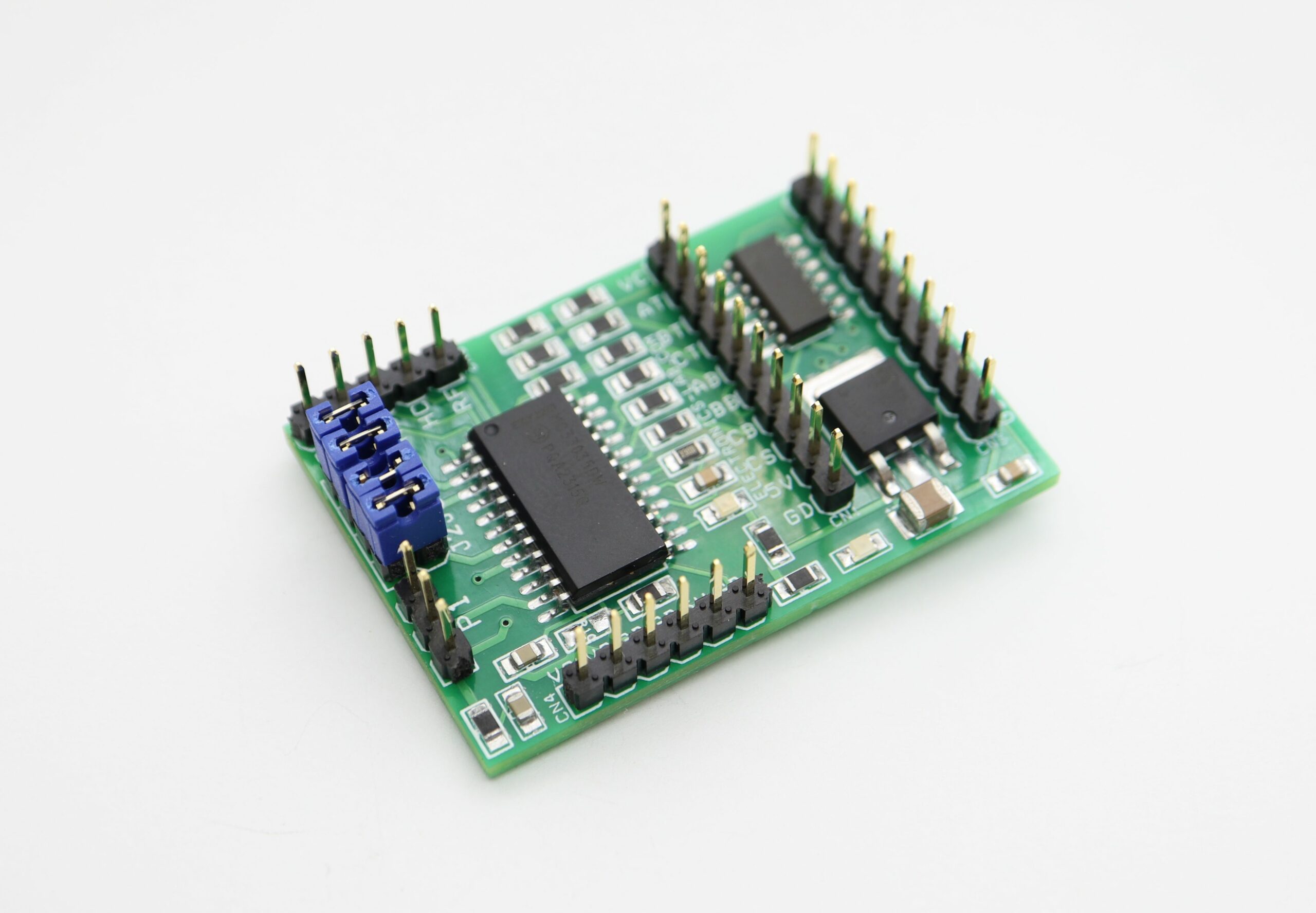
The board shown here is a breakout board for MC33035 brushless motor controller. It requires an output buffer IPM module or Mosfets to complete the closed loop brushless motor driver. MC33035 IC is the heart of the project; the project provides 6 PWM pulses as well 6 Inverse pulses outputs. On board Jumpers helps to change the Direction, Enable, Brake, and 60/120 phasing Header connector provided to connect the Hall sensors and supply, on board LED for Power and fault, P1 potentiometer helps to change the speed.
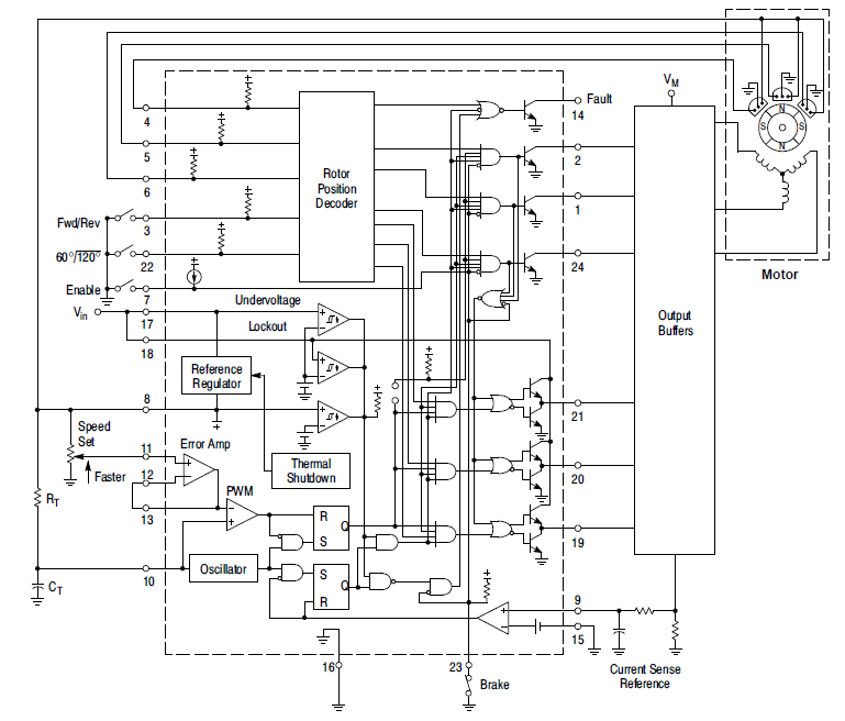
The MC33035 is a high performance second generation monolithic brushless DC motor controller containing all of the active functions required to implement a full featured open loop, three or four phase motor control system. This device consists of a rotor position decoder for proper commutation sequencing, temperature compensated reference capable of supplying sensor power, frequency programmable saw tooth oscillator, three open collector top drivers, and three high current totem pole bottom drivers ideally suited for driving power MOSFETs. Also included are protective features consisting of under voltage lockout, cycle−by−cycle current limiting with a selectable time delayed latched shutdown mode, internal thermal shutdown, and a unique fault output that can be interfaced into microprocessor controlled systems. Typical motor control functions include open loop speed, forward or reverse direction, run enable, and dynamic braking. The MC33035 is designed to operate with electrical sensor phasings of 60°/300° or 120°/240°, and can also efficiently control brush DC motors.
MC33035 Brushless motor driver breakout board – [Link]
Measuring distance is so important in today’s world that things like driverless cars will be impossible without it, that description is probably enough to describe how important knowing the distance between two objects can be. For that reason, today we will be building a distance meter using the Arduino and the HC-SR04 ultrasonic sensor.
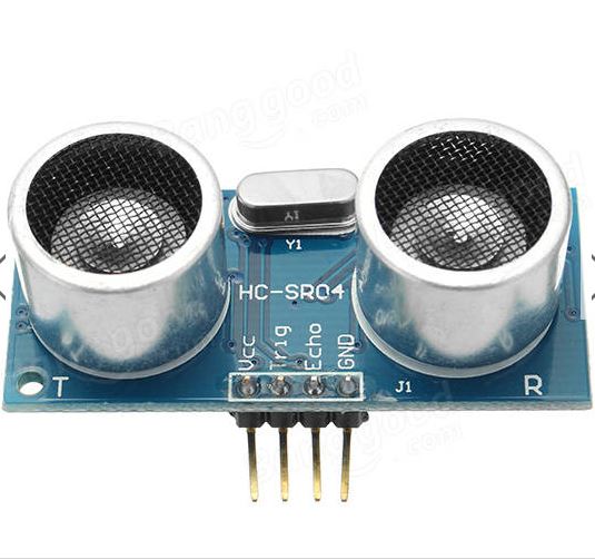
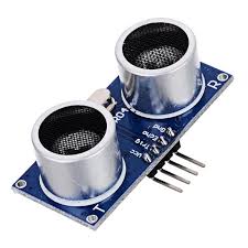
The HC-SR04 ultrasonic sensor is a cheap ranging sensor capable of measuring a distance between 20 – 400cm without contact and at an accuracy of up to 3mm. The sensor is made up of a transmitter and receiver with operating frequency of around 40khz. It uses the echo principle for distance measurement by emitting an ultrasonic wave of 40khz. If there is an object in its path, the emitted wave is reflected and the reflected signal is received via the receiver. The time elapsed between the transmission of the signal and the reception of the echo is then used to determine the distance between the sensor and an object in its path.
Arduino distance meter with Ultrasonic Sensor (HC SR04) and Nokia 5110 LCD display – [Link]
The board shown here is a breakout board for MC33035 brushless motor controller. It requires an output buffer IPM module or MOSFETs to complete a closed-loop brushless motor driver circuit. MC33035 IC is the heart of the project. The board provides 6 PWM pulses as well as 6 Inverse pulse outputs. On-board Jumpers help to change the Direction, Enable, Brake, and 60/120 phasing. A header connector is provided to connect the Hall sensors and supply, onboard LED for Power and fault indication, and a P1 potentiometer helps to change the motor speed.
MC33035 Brushless DC Motor Controller
The MC33035 is a high-performance second-generation monolithic brushless DC motor controller containing all of the active functions required to implement a full-featured open loop, three or four-phase motor control system. This device consists of a rotor position decoder for proper commutation sequencing, temperature compensated reference capable of supplying sensor power, frequency programmable sawtooth oscillator, three open collector top drivers, and three high current totem pole bottom drivers ideally suited for driving power MOSFETs. Also included are protective features consisting of under voltage lockout, cycle−by−cycle current limiting with a selectable time-delayed latched shutdown mode, internal thermal shutdown, and a unique fault output that can be interfaced into microprocessor-controlled systems. Typical motor control functions include open loop speed, forward or reverse direction, run enable, and dynamic braking. The MC33035 is designed to operate with electrical sensor phasings of 60°/300° or 120°/240°, and can also efficiently control brush DC motors.
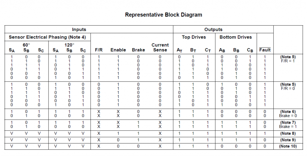
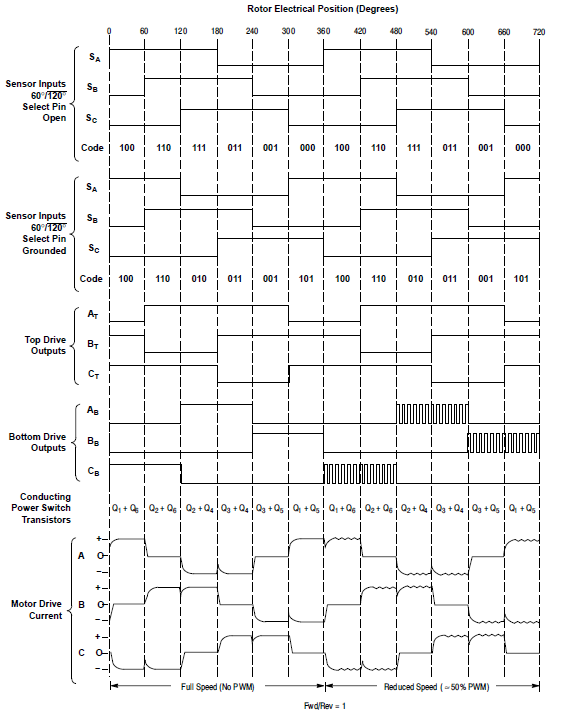
An internal rotor position decoder monitors the three sensor inputs (Pins 4, 5, 6) to provide the proper sequencing of the top and bottom drive outputs. The sensor inputs are designed to interface directly with open collector-type Hall Effect switches or opto-slotted couplers. Internal pull−up resistors are included to minimize the required number of external components. The inputs are TTL compatible, with their thresholds typically at 2.2 V. The MC33035 series is designed to control three-phase motors and operate with four of the most common conventions of sensor phasing. A 60°/120° Select (Pin 22) is conveniently provided and affords the MC33035 to configure itself to control motors having either 60°, 120°, 240° or 300° electrical sensor phasing. With three sensor inputs, there are eight possible input code combinations, six of which are valid rotor positions. The remaining two codes are invalid and are usually caused by an open or shorted sensor line. With six valid input codes, the decoder can resolve the motor rotor position to within a window of 60 electrical degrees. The Forward/Reverse input (Pin 3) is used to change the direction of motor rotation by reversing the voltage across the stator winding. When the input changes state, from high to low with a given sensor input code (for example 100), the enabled top and bottom drive outputs with the same alpha designation are exchanged (AT to AB, BT to BB, CT to CB). In effect, the commutation sequence is reversed and the motor changes directional rotation.
Motor on/off control is accomplished by the Output Enable (Pin 7). When left disconnected, an internal 25 mA current source enables sequencing of the top and bottom drive outputs. When grounded, the top drive outputs turn off and the bottom drives are forced low, causing the motor to coast and the Fault output to activate. Dynamic motor braking allows an additional margin of safety to be designed into the final product. Braking is accomplished by placing the Brake Input (Pin 23) in a high state. This causes the top drive outputs to turn off and the bottom drives to turn on, shorting the motor−generated back EMF. The brake input has unconditional priority over all other inputs. The internal 40 kΩ pull−up resistor simplifies interfacing with the system safety switch by ensuring brake activation if opened or disconnected. The commutation logic truth table is shown in Figure 20. A four-input NOR gate is used to monitor the brake input and the inputs to the three top drive output transistors. Its purpose is to disable braking until the top drive outputs attain a high state. This helps to prevent simultaneous conduction of the top and bottom power switches. In half-wave motor drive applications, the top drive outputs are not required and are normally left disconnected. Under these conditions braking will still be accomplished since the NOR gate senses the base voltage to the top drive output transistors.
Continuous operation of a motor that is severely overloaded results in overheating and eventual failure. This destructive condition can best be prevented with the use of cycle−by−cycle current limiting. That is, each on−cycle is treated as a separate event. Cycle−by−cycle current limiting is accomplished by monitoring the stator current build−up each time an output switch conducts, and upon sensing an over-current condition, immediately turning off the switch and holding it off for the remaining duration of the oscillator ramp−up period. The stator current is converted to a voltage by inserting a ground−referenced sense resistor. The voltage developed across the sense resistor is monitored by the Current Sense Input (Pins 9 and 15), and compared to the internal 100 mV reference. The current sense comparator inputs have an input common mode range of approximately 3.0 V. If the 100 mV current sense threshold is exceeded, the comparator resets the lower sense latch and terminates output switch conduction. The value for the current sense resistor is:
RS=0.1/ Istator(max)
The Fault output activates during an over-current condition. The dual−latch PWM configuration ensures that only one single output conduction pulse occurs during any given oscillator cycle, whether terminated by the output of the error amp or the current limit comparator.
Specifications
Supply 12-18V
Jumpers for Direction, Enable,60/120 Phasing, Brake
Measuring distance is so important in today’s world that things like driverless cars will be impossible without it, that description is probably enough to describe how important knowing the distance between two objects can be. For that reason, today we will be building a distance meter using the Arduino and the HC-SR04 ultrasonic sensor.
The HC-SR04 ultrasonic sensor is a cheap ranging sensor capable of measuring a distance between 20 – 400cm without contact and at an accuracy of up to 3mm. The sensor is made up of a transmitter and receiver with operating frequency of around 40khz. It uses the echo principle for distance measurement by emitting an ultrasonic wave of 40khz. If there is an object in its path, the emitted wave is reflected and the reflected signal is received via the receiver. The time elapsed between the transmission of the signal and the reception of the echo is then used to determine the distance between the sensor and an object in its path.
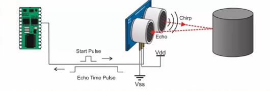
HC-SR04 Operation Principle
The sensor has four pins, VCC, GND, Trig and Echo with trig and echo representing the transmitter and receiver pins respectively.
Distance Meter
Some other features of the sensor includes;
Power Supply:+5V DC
Quiescent Current : <2mA
Working Current: 15mA
Effectual Angle: <15°
Ranging Distance : 2cm – 400 cm/1″ – 13ft
Resolution : 0.3 cm
Measuring Angle: 30 degree
Trigger Input Pulse width: 10uS
Dimension: 45mm x 20mm x 15mm
The goal of this tutorial will be to measure distance using the ultrasonic sensor and display it on both the serial monitor and the Nokia 5110 LCD.
Required Components
The following components are needed for this project;
As usual, the exact components used for this tutorial can be bought by following the link attached to each of them.
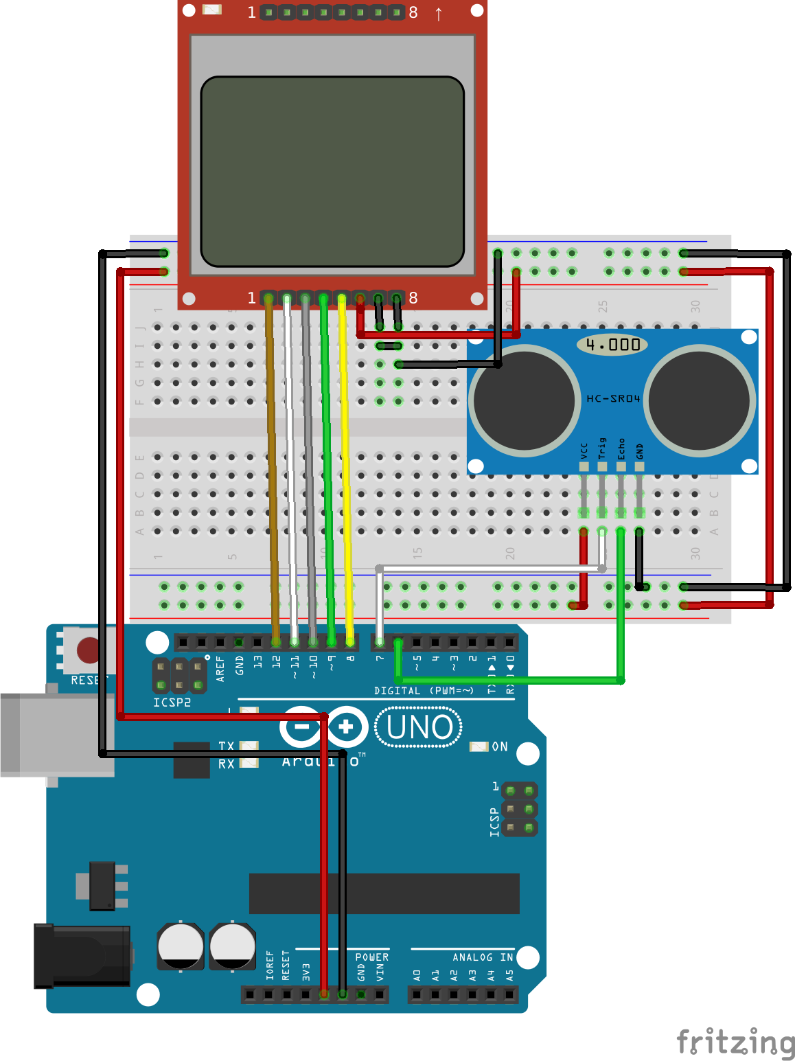
Schematics
Connect the components as shown in the schematics below.
Schematics
To make the schematics easy to follow, as usual, the pin maps showing how each component connects to the other is described below. Connecting the N0kia 5110 LCD to the Arduino is an art that we have perfected over several tutorials, an example of which can be found here, but for the purpose of this tutorial, we will still include the pin map so you can easily connect it if following that schematic is a little bit difficult. The Ultrasonic, on the other hand, is a very easy component to work with, it has just four pins and all at the same voltage/logic level at which the Arduino operates making it almost plug and play.
Double check the connections one last time to be sure everything is as it should be.
Code
There are two codes for this project, the first one is for people who don’t have the Nokia5110 LCD display and are comfortable with viewing the data over serial monitor.The second one integrates the LCD display and allows the display of the value on the LCD.
The working of the code can be better understood by going through the description of how the HC-SR04 works above. The goal of the code is, simply put, to send a signal out via the trigger pin of the ultrasonic sensor and calculate the time it takes to receive the signal back via the echo pin of the sensor. Convert this time to distance and display either on the serial monitor (code sample 1) or on the Nokia 511o LCD(code sample 2). Both codes, as usual, are attached to the zip file under the download section.
Code for Distance Meter without Display
The first thing we will do is declare the pins of the Arduino to which the pins of the ultrasonic sensor are connected.
//Written by Nick Koumaris
//info@educ8s.tv
//educ8s.tv
#define echoPin 6 // Echo Pin
#define trigPin 7 // Trigger Pin
Next, we initialize variables that will be used to store some of the information that we will be working with.
int maximumRange = 250; // Maximum range needed
int minimumRange = 1; // Minimum range needed
long duration, distance; // Duration used to calculate distance
With that out of the way, we then move into the void setup() function. Since we will be primarily be using the serial monitor to display the distance, we must initialize it, with a baud rate of 9600, after which we set the pin mode of the sensor’s pin with the trigger pin being set as output and echo pin as input.
To simplify things, a function was used to get the distance from the ultrasonic sensor and then display it within the void loop. The first thing we do is call the function to read the distance, then an if statement is used to check if the distance read by the sensor, is within the sensor’s range to reduce error which occurs when the sensor’s limit is exceeded.
If the sensor is within range, it is printed else, out of range is displayed.
The distance calculation is done using the readdistance() function. The function achieves the distance determination by sending a pulsed signal out through the trig pin by turning it low and high with a delay in between, and the echo is received via the echo pin using the Arduino inbuilt pulsein function. As specified by the datasheet, the time is then divided by 58.2 to get the distance in Cm.
//Written by Nick Koumaris
//info@educ8s.tv
//educ8s.tv
#define echoPin 6 // Echo Pin
#define trigPin 7 // Trigger Pin
int maximumRange = 250; // Maximum range needed
int minimumRange = 1; // Minimum range needed
long duration, distance; // Duration used to calculate distance
void setup() {
 Serial.begin (9600);
 pinMode(trigPin, OUTPUT);
 pinMode(echoPin, INPUT);
}
void loop() {

readDistance();

if(distance>minimumRange && distance < maximumRange)
{
 Serial.println(distance);
}else
{
  Serial.println("Out of range...");
}
 delay(50);
}
int readDistance()
{
 digitalWrite(trigPin, LOW);
 delayMicroseconds(2);

 digitalWrite(trigPin, HIGH);
 delayMicroseconds(10);

 digitalWrite(trigPin, LOW);
 duration = pulseIn(echoPin, HIGH);

 distance = duration/58.2;
}
Code for Distance Meter with Display
The second code as explained previously is for those who have the Nokia 5110 LCD.
To be able to use the Nokia 5110 LCD easily, we will be using its library which can be downloaded from this link. To give the display a good look we created a UI file which is part of the LCD code file attached to the zip file under the download section. How to work with the Nokia 5110 LCD to create your own UI, custom graphics etc has been covered in a previous tutorial here.
To get started with the code, we include the LCD library and define the pins to which both the ultrasonic sensor and LCD are connected to on the Arduino.
Next, we set the minimum and maximum range of values which the ultrasonic sensor recognizes and we declare the variables, (distance and duration) which will be used to store corresponding data in the code.
int maximumRange = 250; // Maximum range needed
int minimumRange = 1; // Minimum range needed
long duration, distance; // Duration used to calculate distance
Next, we proceed to the setup() function where we set the pin modes of the Ultrasonic sensor pins, after which we initialize the LCD and instruct it to use the fonts we declared initially.
With that done, we move into the void loop section.
We initialize the string length to zero, clear the screen and then draw the UI we created, after which we call the read distance function, calculate the string length of the distance received and display it on the LCD using the print distance function.
Connect the Arduino board to your computer, launch the IDE and paste the code into it. Don’t forget to add the UI file to the Arduino sketch folder for the code before uploading as this may cause errors to occur. The UI file is part of the files in the zip file under the downloads section.
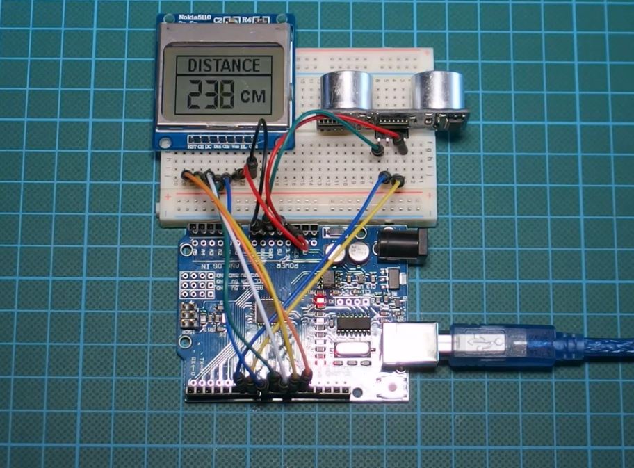
Demo
Upload the code to your board and you should see the distance on your display like the image above. If you are using the Serial monitor as the display, launch it too, you should see the distance streaming in as seen in the image below.
Demo of Serial Monitor as Display
works right? Yea!
That’s it for this tutorial guys, as usual, you can drop comments and questions via the comment section.
Till next time
You can watch the video of this tutorial on youtube here.
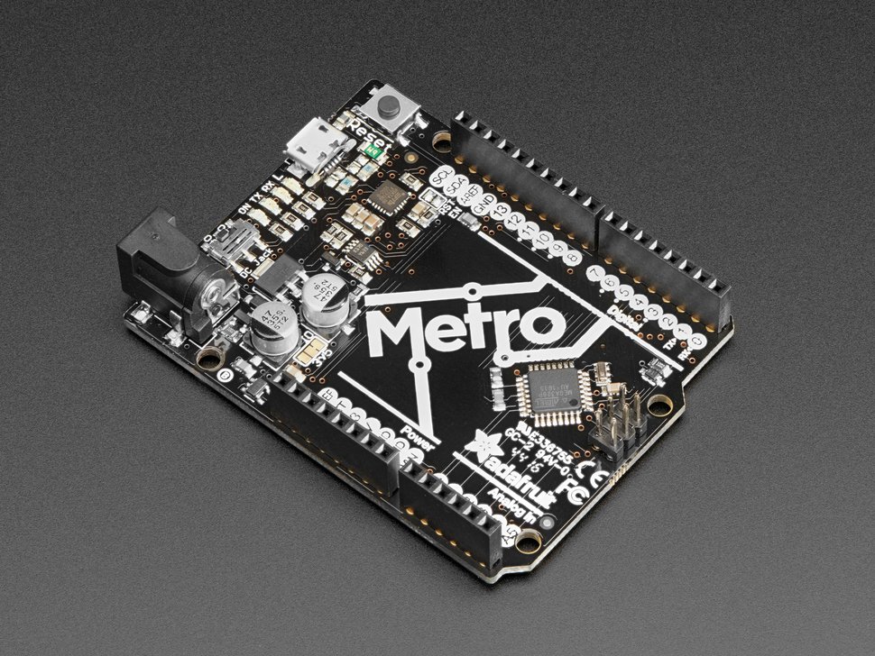
The Adafruit Metro 328 development board is an alternative to the Arduino Uno with an equivalent and compatible board design. It’s designed and manufactured by Adafruit. The Metro 328 just like other Arduino Uno clones is also based on the famous Atmega 328P that has been used in various development boards and projects.
Adafruit Metro 328
The Metro 328 offers an ATmega328 microcontroller with Optiboot (UNO) Bootloader and a ton of other features you won’t find on the Arduino Uno board. The Metro board is equipped with 19 GPIO pins unlike the Arduino Uno 14, analog inputs, UART, SPI, I2C, timers, and PWM. Six of its GPIO pins are for Analog input with two reserved for the USB to Serial Converter. Just like the standard Arduino Uno, it also includes 6 PWM pins on 2x 8bit timers and 1x 16bit timers.
Another significant distinction between the Metro and the Arduino Uno is the USB to Serial converter. The Arduino Uno is based on the Atmega USB-UART bridge (ATMEGA16U2), but the Metro 328 is based on the FTDI FT231X that provides excellent driver support in all operating systems with a more reliable data transfer unlike the former. It comes with four indicator LEDs, on the front edge of the PCB, for easy debugging. One green power LED, two RX/TX LEDs for the UART, and a red LED connected to pin PB5.
The Metro board has an on and off switch for the DC jack so you can turn off your setup easily. It also uses the conventional micro USB connector found around. Even though the Logic level of the Metro is 5V, it can be converted to 3.3v logic by cutting and soldering a closed jumper.
The following are the Metro 328P specifications:
ATmega328 microcontroller with Optiboot (UNO) Bootloader
USB Programming and debugging via the well-supported genuine FTDI FT231X
Input voltage: 7-9V (a 9VDC power supply is recommended)
5V regulator can supply peak ~800mA as long as the die temp of the regulator does not exceed 150*C
3.3V regulator can supply peak ~150mA as long as the die temp of the regulator does not exceed 150*C
5V logic with 3.3V compatible inputs can be converted to 3.3V logic operation
20 Digital I/O Pins: 6 are also PWM outputs, and 6 are also Analog Inputs
6-pin ICSP Header for reprogramming
32KB Flash Memory – 0.5K for bootloader, 31.5KB available after bootloading
Next Tuesday 27th February – Thursday 1st March, meet OEMsecrets at the world’s leading embedded systems conference in Nuremberg, Embedded World. Get your free ticket and meet us for a Tucher or two on stand 4A-612 to rehydrate!
We’ll showcase our latest site developments, including new API capabilities and future site features such as our parametric search. As part of our badge scan promotion and in partnership with Avnet Silica, we’ll also be handing out high-value giveaways. We all look forward to welcoming you on to our booth. See you next week, prost!