With the arrival of the IoT and the need for control, devices now need to do more than perform the basic functions for which they are built, they need to be capable of communicating with other devices like a mobile phone among others. There are different communication systems which can be adapted for communication between devices, they include systems like WiFi, RF, Bluetooth among several others. Our focus will be on communication over Bluetooth.
Today we will be building an Arduino based project which communicates with an app running on a smartphone (Android) via Bluetooth.
Arduino Communication with an Android App via Bluetooth – [Link]
With the arrival of the IoT and the need for control, devices now need to do more than perform the basic functions for which they are built, they need to be capable of communicating with other devices like a mobile phone among others. There are different communication systems which can be adapted for communication between devices, they include systems like WiFi, RF, Bluetooth among several others. Our focus will be on communication over Bluetooth.
Today we will build an Arduino based project which communicates with an app running on a smartphone (Android) via Bluetooth.
Using a mobile app to switch an LED on/off
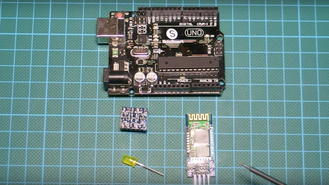
For simplicity, the goal of the project is to switch a LED connected to the Arduino using the mobile app. We will be using the HC06 Bluetooth module as the major ingredient in this tutorial.
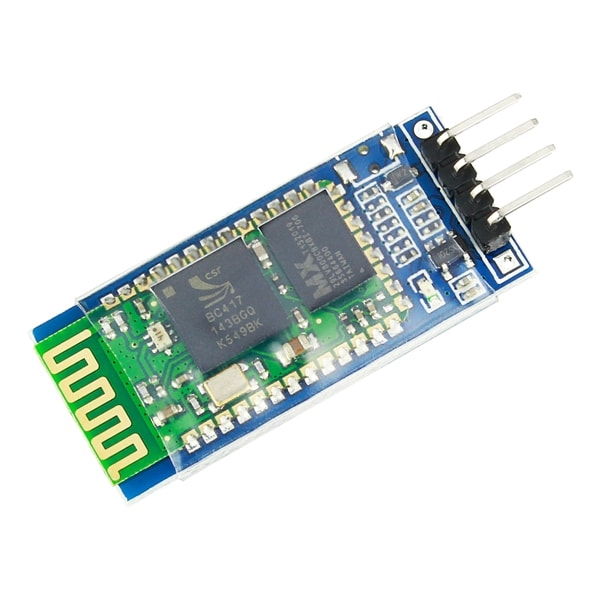
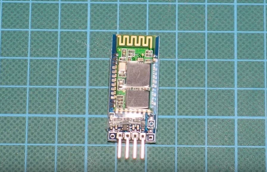
The HC06 Bluetooth Module is a slave only version of the HC05 Bluetooth module. It has 4 pins and communicates with a microcontroller via serial interface.
HC06 Bluetooth Module
The HC06 Bluetooth module is a 3.3v logic level based device and thus if directly connected to the Arduino, will sometimes be unable to process the message received from the Arduino which is a 5v Level logic level device unless there exists some form of level shifting, although the Arduino can easily understand the data being sent from the Bluetooth module since it uses a higher logic level. The level shifting/conversion can be achieved either by use of a voltage divider or a level shifter module (like we did in this tutorial).
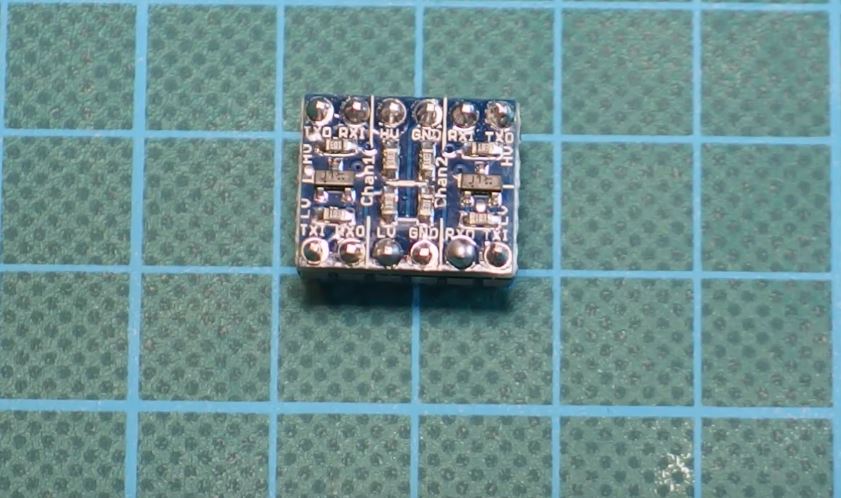
The shifter module (shown in the image below) helps with the easy transition from one voltage to the other. The level shifter has two sides, the high voltage side (marked HV) and the low voltage side (Marked LV). The shifter allows you to connect the desired low voltage output on the LV side and the high voltage line also to the HV. More details on connecting the level shifter are discussed in the schematics section.
Voltage Level Shifter Module
Required Components
The following components are required for this tutorial;
As usual, the exact components used for this tutorial can be bought by following the link attached to each of them.
Schematics
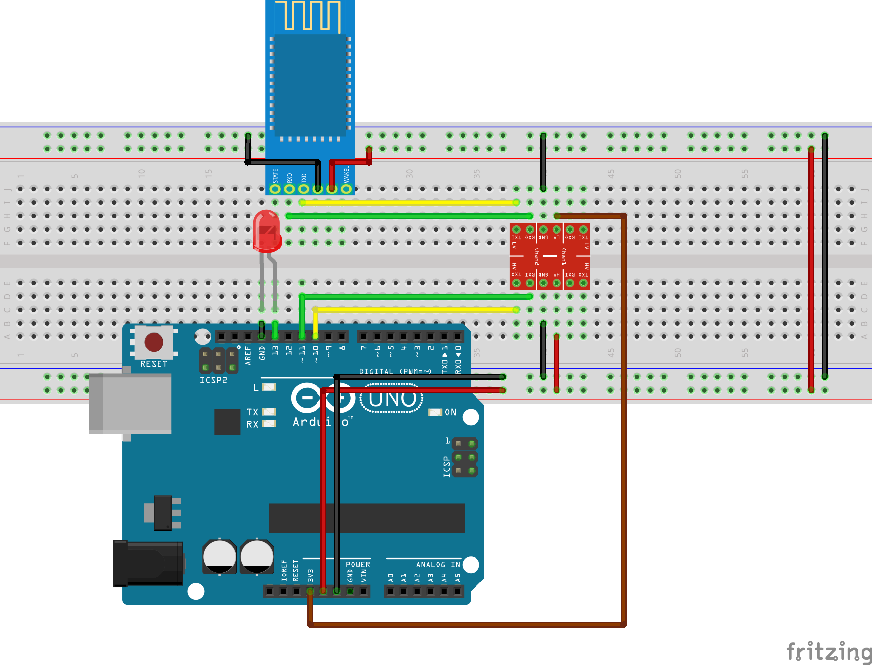
Connect the components as shown in the schematics below.
Schematics
As earlier mentioned, the HC06 Bluetooth module is a 3.3v logic level device, to make it compatible with the logic level of the Arduino (which is 5v) we need to use a logic level shifter/converter as shown in the schematics above. To make the schematics a bit clearer, a pin map of the components and their connections is shown below.
With the components connected and the connection verified, we are ready to build the Android app to be used for the actual control of the LED.
Android App
The app for this project was designed using the MIT app inventor for the sake of simplicity, but it can also be built using any other platform, used for the development of Android apps.
The MIT App Inventor is a scratch like mobile app development platform and its focus is around making programming easy for everyone, thus instead of writing codes, the app programming is done using drag and drop blocks just like the programming platform “Scratch”.
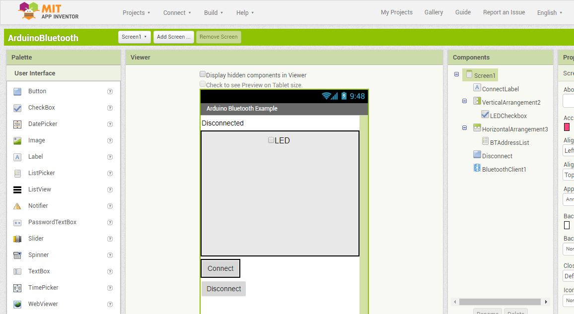
To build the app created for this project, create a new project and design the UI to look like the image below.
UI Design
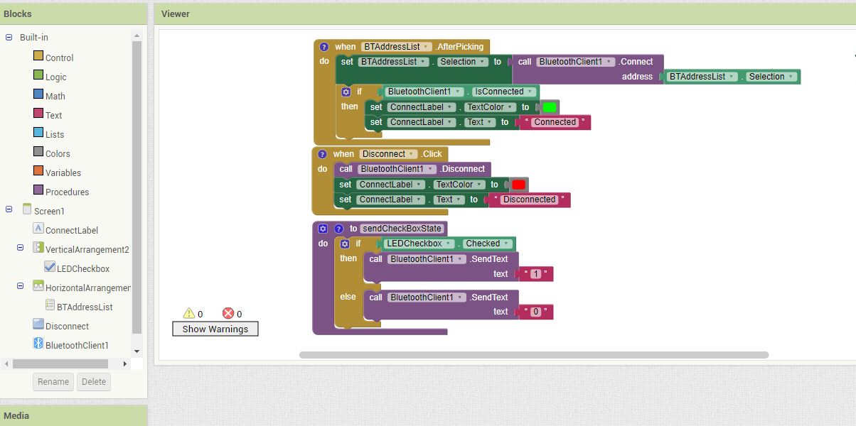
With the UI done, click on blocks and proceed to replicate the blocks below.
Code
compile the app and save as an APK to your computer from which you can transfer to your phone for installation.
The .aia project raw file for the app is part of the files archived in the zip file located under the download section of this tutorial.
The .aia file can be imported into the MIT App inventor workspace and edited to suit your needs and desires.
The APK install ready file is also attached to the zip file, so you can install straight to your phone.
With the app ready, we can now proceed to write the Arduino code to control our device.
Code
The Arduino communicates with the Bluetooth module via serial communication and this makes it really easy to write the code. Since we decided to use software serial and not the Arduino’s hardware serial pins (D0 and D1), we will need the Arduino software serial library. This library gives us the freedom to choose any of the Arduino digital pins as our Rx and Tx pins. The hardware serial pins are the same pins used by the Arduino to communicate with the computer so connecting them to the Bluetooth will cause interference which could hinder the code upload process. Although the pins can be disconnected from the Bluetooth when the code is being uploaded and reconnected after the code has been uploaded but this is not always efficient.
The basic function of the code is to monitor the incoming serial data stream, if it receives a “1”, it turns the LED on and if it receives a “0” it turns the LED off.
To jump in, we will, as usual, give a breakdown of the code to explain each part before the full code is provided. The Arduino code is among the files archived in the zip file under the download section.
The first thing we do while writing the code, as usual, is to import the libraries we will be working with, which in this case is the software serial library.
    /////////////////////////////////////////////////////////////////
   //              Arduino Bluetooth Tutorial     v1.00           //
  //       Get the latest version of the code here:              //
 //         http://educ8s.tv/arduino-bluetooth-tutorial         //
/////////////////////////////////////////////////////////////////

#include <SoftwareSerial.h>
After importing the library, we then declare a variable to hold the characters received from the Bluetooth and the pin on the Arduino to which the LED is connected. We also initialize the Softwareserial library by indicating the pins that will serve as Rx and Tx.
char c;
int  LED = 13;

SoftwareSerial mySerial(10, 11);
Next, we move to the setup() section where we set the pinMode for the pin to which our LED is connected (output) and we start the serial communication with a baud rate of 9600 which is the baud rate at which most recent versions of the HC06 module communicate.
Next, we move to the major part of the code; the void loop() function. The first thing we do is confirm the availability of data from the Bluetooth module, after which we read the data, and use an if statement to compare it to see if it is a 1 or 0. if the data is 1, we turn the LED high, but if its 0, we turn the LED off.
void loop()
{
while (!mySerial.available());
c = mySerial.read();
if (c == '1')
{
digitalWrite(LED, HIGH);
}
if (c == '0')
{
digitalWrite(LED, LOW);
}
}
The Complete code is available below.
/////////////////////////////////////////////////////////////////
// Arduino Bluetooth Tutorial v1.00 //
// Get the latest version of the code here: //
// http://educ8s.tv/arduino-bluetooth-tutorial //
/////////////////////////////////////////////////////////////////
#include <SoftwareSerial.h>
char c;
int LED = 13;
SoftwareSerial mySerial(10, 11);
void setup()
{
  pinMode(LED, OUTPUT);
  mySerial.begin(9600);
}
void loop()
{
  while (!mySerial.available());
  c = mySerial.read();
  if (c == '1')
  {
    digitalWrite(LED, HIGH);
  }
  if (c == '0')
  {
    digitalWrite(LED, LOW);
  }
}
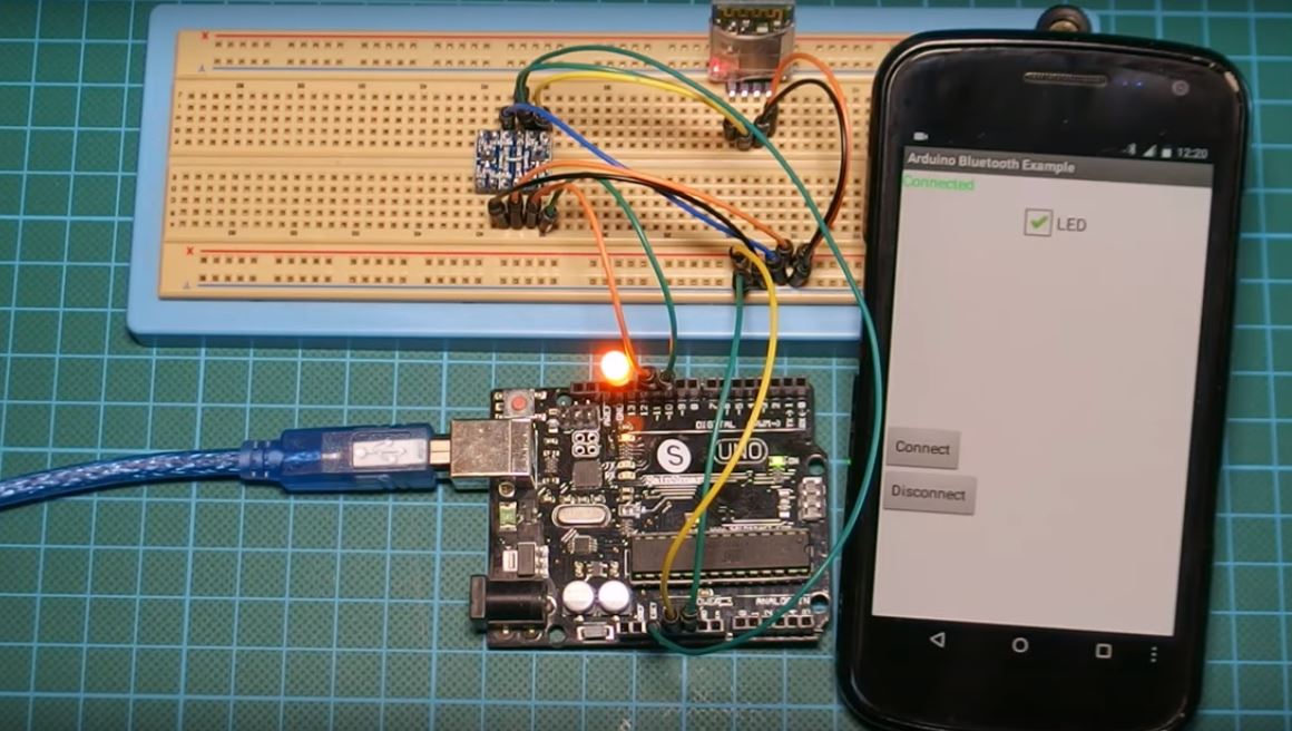
Demo
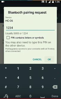
Connect, the Arduino to the computer and upload your code. You should see an LED on the Bluetooth begin to flash, this means it is ready to pair. Turn on your phone’s Bluetooth and you should see hc06 after scanning. connect to it and enter the passkey which is usually 1234.
Passkey
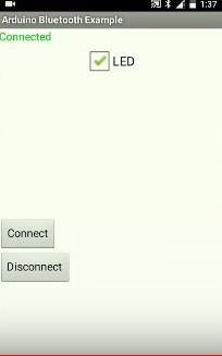
Proceed by launching the app, and click the connect button, it will show the mac address of your hc06. Connect to it and go back to the apps main screen.
After connecting, the app will show connected on the top left corner, you can then check or uncheck the checkbox to turn on or off the led respectively.
App Connected to Device
That’s it for today’s tutorial guys, If you have any question, suggestion or comment, kindly drop them under the comment section.
Till next time.
The video of this tutorial is available on youtube here.
Back in 2012, the arrival of Raspberry Pi started a new era of Single Board Computers – widely known as SBC. It attracted a huge number of hobbyists and tinkerers who are keen to create technology rather than just consuming it. Single board computers made designing complex and computationally expensive projects possible. Robotics, IoT, Computer Vision projects, DIY media center – just name it and SBC will get it done with ease.
Since the massive success of the Raspberry Pi, the market got filled with various single board computers from different developers. Almost all of them have similar features but with some uniqueness.
Nowadays, we can see SBCs as cheap as $9 to as expensive as $250. One should purchase an SBC carefully depending on the budget and the type of the project. This Top 10 List is based on the SBCs that were popular the previous year and it will help you to choose an SBC as per your requirement without much effort.
The Logic of Sorting
While sorting out some products and giving them ranks, the logic of sorting should be clarified. We can sort out SBCs in many ways – performance, form factor, price point, user community etc. In this article, we have kept hobbyists and tinkerers in mind and so, our primary focus is price point and performance at that price. As a result, some extremely powerful boards didn’t rank well just because of being too costly and not affordable by hobbyists. Also, we have not included boards introduced this year (2018) as the list is based on the top boards of the previous year (2017).
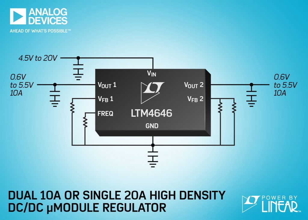
Designed for use in PCIe boards, communications infrastructure, cloud computing-based systems, medical, industrial, and test and measurement equipment, the LTM4646 is a dual 10A or single 20A output, step-down µModule PoL regulator from 5.0 or 12V input supply rails. It targets the PCB area constraints of densely populated system boards to power low voltage and high current devices such as FPGAs, ASICs, microprocessors and GPUs, says Analog Devices.
The LTM4646 includes inductors, MOSFETs, a DC/DC controller and supporting components, and is housed in a 11.25 x 15 x 5.01mm BGA package. Compared to the previous two single 10A output module solutions, the LTM4646 reduces the solution size of more than 25 per cent, says Analog Devices.
Total output voltage DC accuracy is guaranteed at ±1.5 per cent over line, load and temperature (-40 to +125 degree C). The onboard remote sense amplifiers on both outputs compensate for voltage drop caused by trace impedance of the PC board due to large load currents. Internal or external feedback loop compensation is selectable, enabling users to optimise loop stability and transient performance while minimising the number of output capacitors.
Peak efficiency at 12VIN to 1.0VOUT is 86 per cent. With 200LFM air flow, the LTM4646 delivers a full 20A continuously up to 85 degree C ambient, adds Analog Devices. The current mode architecture allows multi-phase parallel operation to increase output current with good current sharing, says the company.
The LTM4646 operates from 4.5 to 20V input, standalone. When 5.0V external bias is available, the device can operate from 2.375V. The output voltages are adjustable from 0.6 to 5.5V, enabling the LTM4646 to generate low voltage for digital devices but also 2.5, 3.3 and 5.0V, for system buses. The switching frequency can be programmed from 250kHz to 1.3MHz with one resistor, and can also be synchronised to an external clock ranging from 300kHz to 1MHz for noise-sensitive applications.
The LTM4646 has over-voltage and over-current protection.
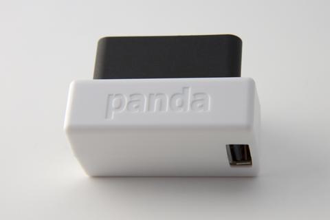
Comma.ai is a self-driving car startup founded by George Hotz, the American hacker known for unlocking the iPhone and the PlayStation 3. Comma AI who originally wanted to build self-driving car kit, canceled their initial project due to safety concerns from NHTSA but later open-source their project and has now launched a Panda, an On-Board Diagnostics (OBD) II adapter that is expected to expose a car sensor data with the hopes of turning that information for self or assisted driving application.
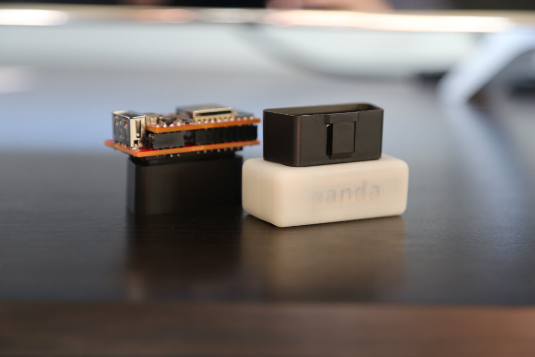
Panda OBD-II Dongle
Panda is a small size OBD II dongle and will plug into the port of most new cars made since 1996 with preference giving to vehicles of 2010 and above. Panda supports 3 CAN (Controller Area Network), 2 LIN (Local Interconnect Network) and 1 GMLAN (General Motor Local Area Network) for access to almost all of the sensors in most of the cars on the road. It also includes WiFi and USB port to help interface with a computer and smartphone.
With a dimension of 34 mm x 50 mm x 27 mm, Panda can read a host of data. Panda will be able to measure the car speed, location (if available), fault codes, braking force, engine speed, gas level, and many more. To help parse all that information Comma AI also launched Cabana a CAN analysis tool.
Panda can be paired with Openpilot, the company’s open-source autonomous driving software and this pairing could be used to take control of a compatible vehicle’s gas, brakes, lights, and steering.
Some Specifications of Panda dongle
Dimensions – 34mm x 50mm x 27mm
Weight: 32g
Car Interfaces –
3x CAN
2x LIN
1x GMLAN
Connectivity – USB (with fast charging support) & WiFi
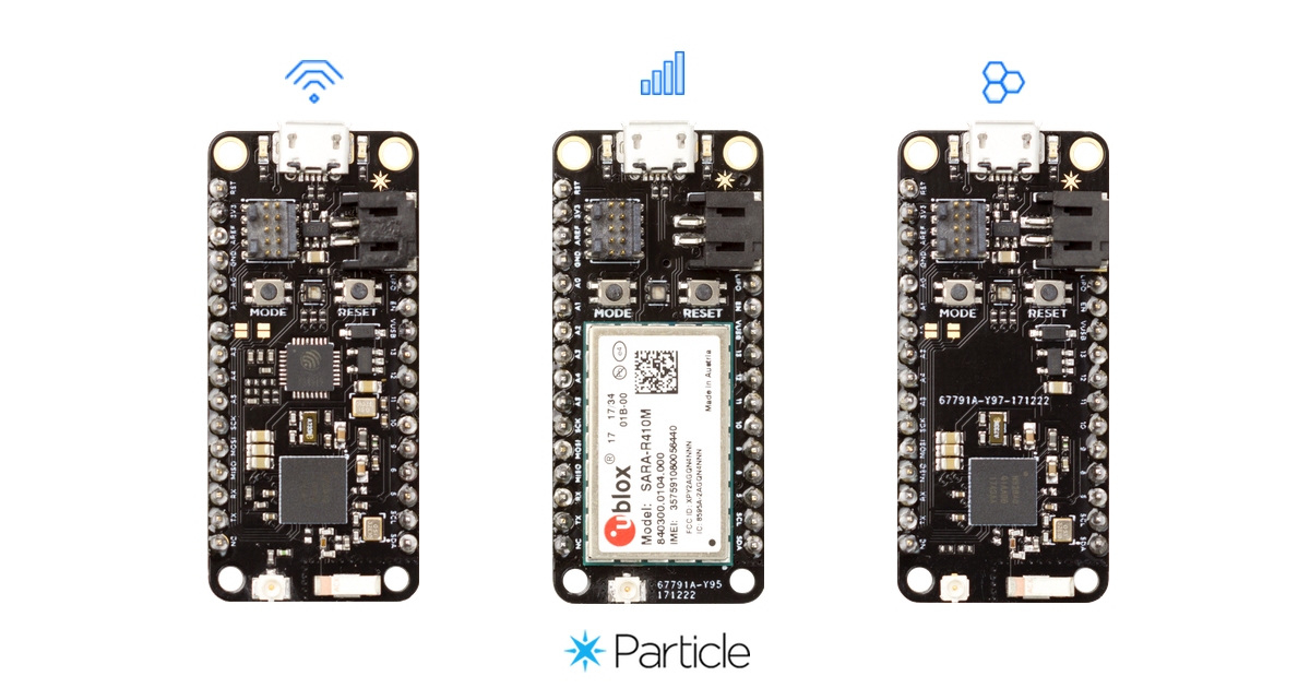
Particle, which has been known for its collection of IoT focused development boards, and its Internet of Things (IoT) platform (Particle Cloud) has launched a new set of mesh network-enabled IoT development kits called Particle Mesh. Particle Mesh is expected to provide developers more insight into implementing mesh networking technology. They help to collect sensor data, exchange local messages, and share their connection to the cloud.
Particle Mesh Hardware
Particle Mesh features a new family of mesh-ready devices with Wi-Fi, BLE and LTE connectivity and also integrated with the Particle device cloud. Particle mesh consists of three main boards: The Argon, The Boron, and the Xenon. Each of these Particle Mesh boards has at least one form of outside connectivity option (LTE/3G/2G, Wi-Fi or Bluetooth) and an onboard mesh network hardware to facilitate setting up a mesh network for local communications between sensors and other particle mesh boards. All three devices are built around the Nordic nRF52840 MCU + BLE + mesh radio and follow the Adafruit Feather specification making it compatible with most Adafruit FeatherWing hardware accessories. Continue reading “Particle Mesh – A Mesh-Enabled IoT Development Kits.”
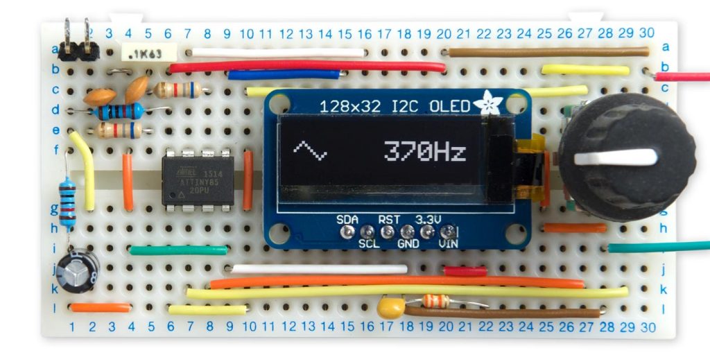
David Johnson-Davies build a tiny function generator based on ATtiny85 microcontroller. He writes:
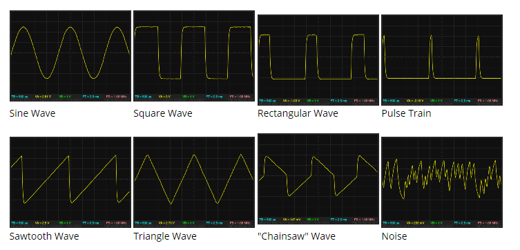
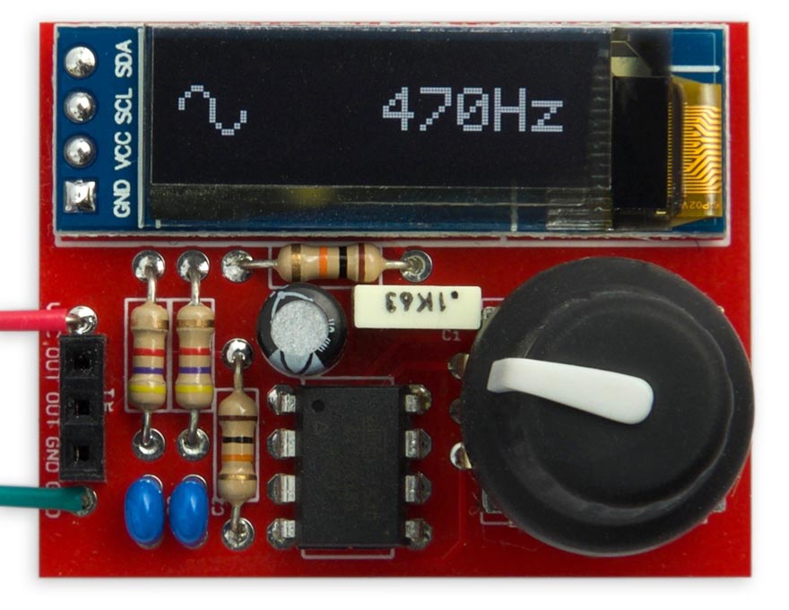
This article describes a simple function generator based on an ATtiny85. It can generate triangle, sawtooth, square, and rectangular waves, a pulse train, and noise. The frequency can be adjusted using a rotary encoder between 1Hz and 5kHz in steps of 1Hz, and the selected waveform and frequency is displayed on an OLED display.
This project really puts the ATtiny85 through its paces; it’s generating 8-bit samples at a 16kHz sampling rate, decoding the rotary encoder, switching between waveforms, and updating the OLED display via I2C.
ATtiny85 Function Generator – [Link]
[update 08-02-2019] “David” designed a PCB for this project and provided some additional build details about it.
Our friends on educ8s.tv uploaded a new video. Check it out.
Welcome to this ESP32 Deep Sleep tutorial with the Arduino IDE! Today we are going to learn how to put the ESP32 chip into the Deep Sleep mode in order to conserve power and make our projects battery friendly. There is a lot to cover so let’s get started! The ESP32 chip is a fantastic new chip with great features. It offers a lot of processing power, two 32 bit cores, a lot of memory, Bluetooth and WiFi in a small and easy to use chip. One of the most interesting things about the ESP32 chip is that it offers a low-power deep sleep mode which is very easy to use. Let’s see how to use it.
ESP32 Deep Sleep Tutorial for Low Power Projects – [Link]
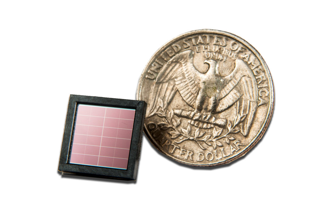
Saelig Company, Inc. (www.saelig.com) has introduced the patented Sol Chip Saturn802 Energy Harvester IC – a unique photovoltaic (PV) cell which can produce output voltage levels of 0.75V, 1.5V, 2.25V, 3.0V, 4.5V, and 9V, which existing solar cells cannot do. The maximum power which can be obtained in full daylight is around 10mW, or 55uW in office lighting, so the Saturn802 IC is targeted at low-power applications. The size of the die is approximately 1cm by 1cm, and the stable voltage levels are available from separate pins of the device. The IC can be used with or without a back-up battery.
Sol Chip’s unique technology integrates solar energy conversion principles with very large scale integration (VLSI) techniques to produce a unique ambient light harvesting device that combines photovoltaic layer and microchip circuitry in layers on the same substrate. Although solar cells have been around for a long time, with microchips being the mainstay of electronic devices, no company in the semiconductor industry has successfully integrated solar cells with standard chip manufacturing processes in a cost effective way.
The Sol Chip Energy Harvester allows designers to build low-powered products that can recharge themselves. All that is needed is a small window in the product design or a transparent cover to allow light to reach the surface-mounted Saturn802 chip. This eliminates the need for a battery in low power products, thus removing maintenance and environmental waste issues. Incorporating the Sol Chip Energy Harvester in product designs is ideal for hard-to-reach locations where battery use and routine replacement is inconvenient or prohibitively expensive.
Applications suited to the Saturn802 include wireless sensor networks, drip-irrigation systems, wearable electronics, smart city solutions like parking or security and utility meters, data loggers, shelf labeling, GPS emergency locators, animal tracking devices, GPS asset/container tracking, autonomous environmental and pollution measurement devices, and RFID devices. Saturn802 designs can operate continuously for more than ten years with no maintenance requirements. In wireless products this also eliminates the significant costs and time associated with wiring connections for the deployed sensors, reducing system cost of ownership.
Forming an “everlasting battery”, the Saturn802 solar cells are available on an evaluation board, the Eval-802, allowing users to develop their own power regulation circuitry for handling differing light and load conditions. For a ready-made solar solution using the Saturn802 cell, the SCP-2801 board provides all necessary circuitry to provide constant 24/7 output.
Made in Israel by Sol Chip Ltd., an innovative solar products manufacturer, the Sol Chip Saturn802 Energy Harvester IC and the SCP-2801 Evaluation Kit are available now from Saelig Company, Inc., Sol Chip’s authorized North American distributor.
Creating a stable system and development ecosystem to reduce time to market for new applications
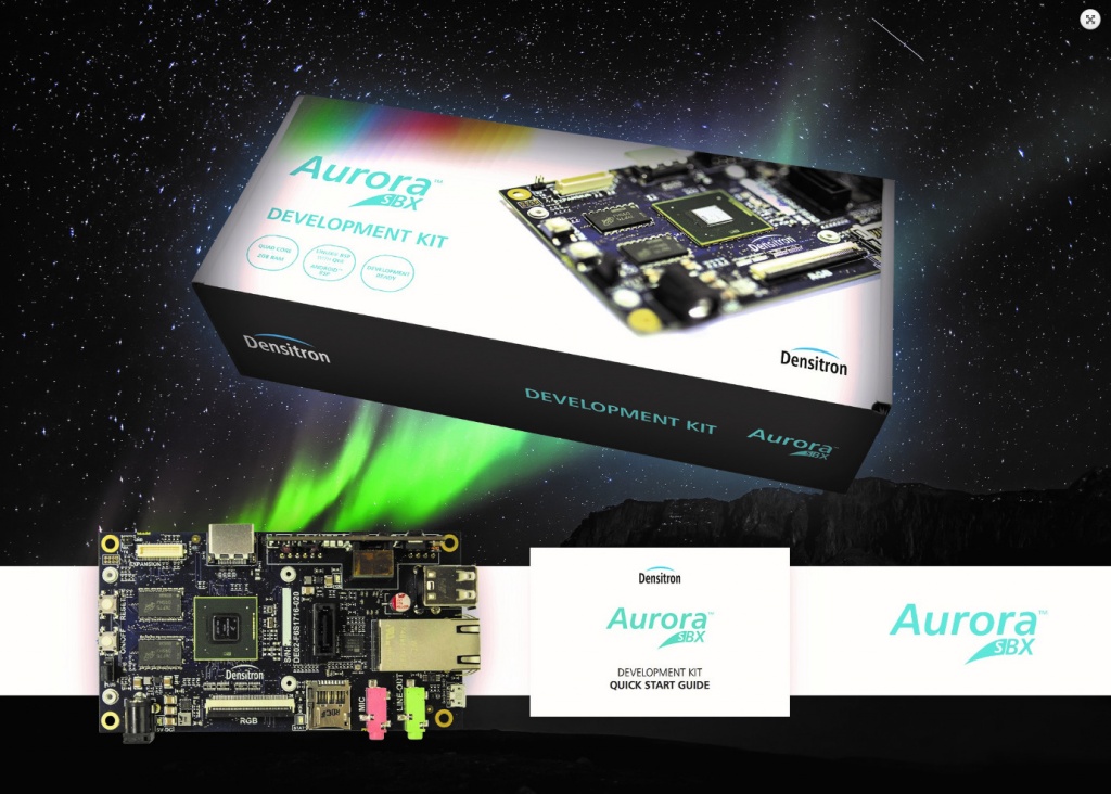
Densitron, a creator of display technologies and global leader in display, monitor and embedded computing solutions, has launched its new single board computer (SBC) appropriately named “Aurora SBX™” (derived from the Latin for first light), along with its extremely versatile application-specific software. Developed by the company’s Embedded division, this original board will help engineers using Densitron displays and electronics within new applications to accelerate the development process and bring their products to market faster.
Aurora SBX™ combines with, and supports, a variety of Densitron displays to provide a Human Machine Interface (HMI) package. Designed specifically to drive various displays from within Densitron’s vast range – with PCT multitouch or haptic input and up to full HD resolution – and to fit within a 5” display outline, the package provides an out-of-the-box, development-ready solution which can be integrated without substantial development resources. Continue reading “Single board computer and software are development system for HMI”