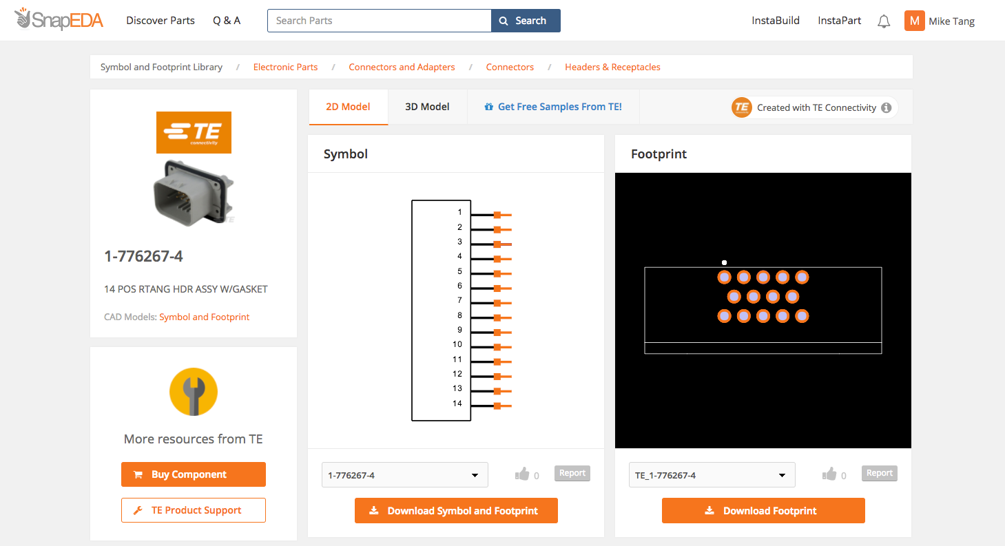
Engineers can now easily design-in a wide variety of components with free symbols & footprints
SCHAFFHAUSEN, Switzerland and SAN FRANCISCO, CA (February 14, 2018) — TE Connectivity (TE), a world leader in connectivity and sensors, and SnapEDA, the Internet’s first parts library for circuit board design, are collaborating to make more than 25,000 new digital models available to electronics designers, helping them bring their products to market faster.
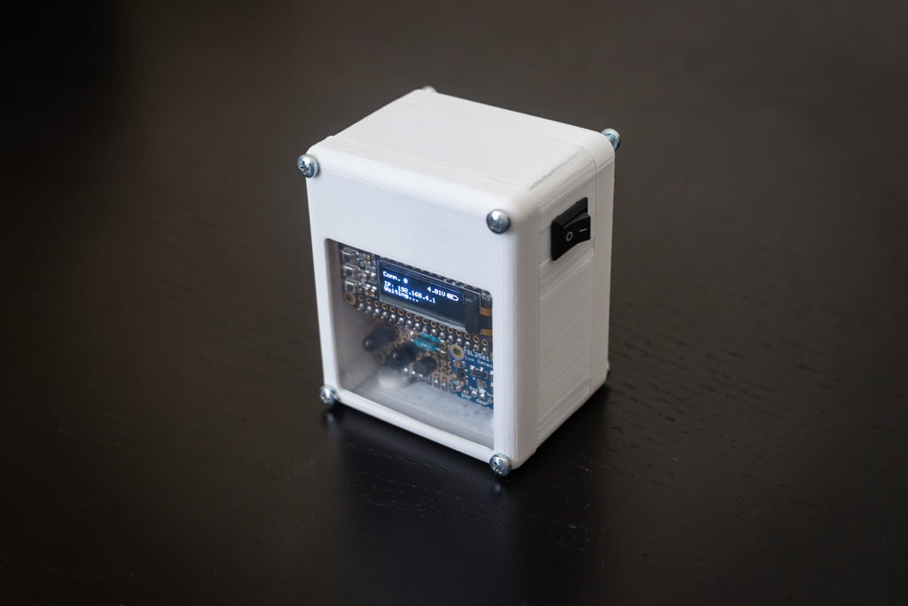
Lenin @ movingelectrons.net build a DSLR camera wireless controller and documented the process. He writes:
I’ve been experimenting with time-lapse shots for a while now. Unfortunately, time-lapse shooting options on most DSLR and mirrorless cameras are somewhat limited. At the time of this writing, Sony doesn’t even include the feature on their high end cameras by default (you need to buy an “App” and download it to the camera).
Some time ago, I posted the setup I had been using for shooting time-lapses using a Raspberry Pi, a portable battery and a USB cable. It got the job done, but using a Raspberry Pi as a time-lapse controller seems a bit overkill. I also wanted to get rid of the cables and the need for carrying around a big battery pack. Thus, I came up with this little device.
Building a DSLR Camera Wireless Controller – [Link]
RISC-V is an open specification of an Instruction Set Architecture (ISA). That is, it describes the way in which software talks to an underlying processor – just like the x86 ISA for Intel/AMD processors and the ARM ISA for ARM processors. Unlike those, however, the RISC-V ISA is open so that anyone can build a processor that supports it. Just as Linux revolutionize the software world, RISC-V could create a substantial impact on the hardware world. This open-source chip project is might just go out to break the dominance of proprietary chips offered by Intel, AMD, and ARM.
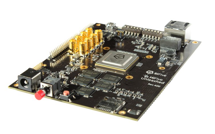
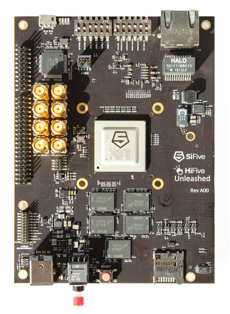
Hi-Five Unleashed-board
Silicon Valley-based company SiFive has released the world first RISC-V based Linux development board called Hi-Five Unleashed. SiFive which has previously released the HiFive1, a RISC-V-based, Open-Source, Arduino-Compatible Development Kit. The HiFive Unleashed is powerful enough to run Linux distributions.
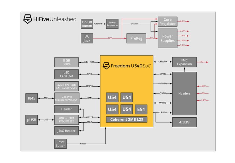
HiFive Unleased Block Diagram
Hi-Five Unleashed was designed around the RISC-V based, quad-core, 1.5GHz U540 SoC (Freedom U540). The Freedom U540 is the first multi-core SoC featuring the open source RISC-V ISA with 4x 1.5GHz “U54” cores and a management core, fabricated with TSMC’s 28nm HPC process, and also the first to offer cache coherence. The U54-MC Core’s high-performance and flexible memory system make it ideal for applications such as AI, machine learning, networking, gateways, and smart IoT devices. It has no GPUs or other coprocessors, but the open source hardware design is intended to encourage third parties to collaborate to develop one.
The Hi-Five Unleashed is a minimalist board that uses one Freedom U540 paired with 8GB DDR4 ECC RAM, as well as 32MB Quad SPI Flash, a microSD card slot for external storage, a Gigabit Ethernet port, and an FMC connector for future expansion cards. The development board is still barebone for now and mostly intended for developers and not the general public; it lacks hobbyist helpful resources like a video output and USB support, none of those are available on the board.
The following are some of the HiFive Unleashed specifications:
SoC – SiFive Freedom U540 with 4x U54 RV64GC application cores @ up to 1.5GHz with Sv39 virtual memory support
1x E51 RV64IMAC Management Core
2 MB L2 cache
28 nm TSMC process
System Memory – 8GB DDR4 with ECC
Storage – 32MB Quad SPI Flash from ISSI
MicroSD card for removable storage
Connectivity – Gigabit Ethernet port
Debugging – Micro USB port connector to FTDI chip
Expansion – FMC Connector for future add-in cards
Misc – On-off switch, various configuration jumpers
Power Supply – 12V DC input
The board is currently available for order at Crowd Supply for $999 and is expected to ship on June 30th. An earlier access board goes for $1250, which will ship on March 31st. RISC-V has grown from an academic project which first started in 2006 at UC Berkely, and now to a welcome, acceptable alternative to existing ISA and a potential game-changer in the long run.
In the future, we are not only going to build powerful open source based system but also understand their internal working and avoid something like the Spectre and Meltdown bugs that affected the likes of Intel processor.
Ultraviolet rays, also known as UV for short are rays emitted by sun. Due to the depletion of the ozone layer, these rays tend to get to extreme levels that could lead to sunburns etc for those under it, that’s why daily and hourly forecast of the UV index is always available to help people keep track and stay safe. For monitoring purposes, why not own a personal UV meter?
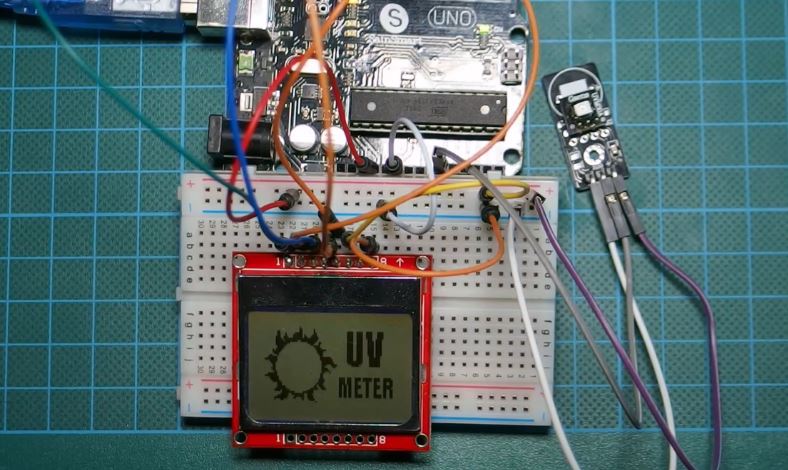
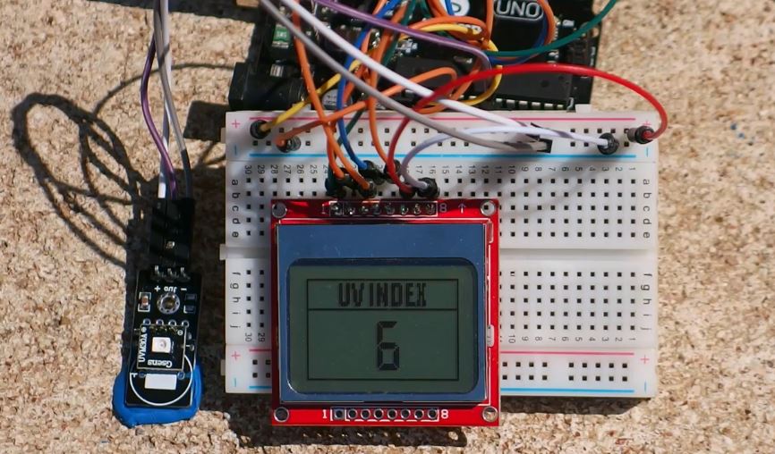
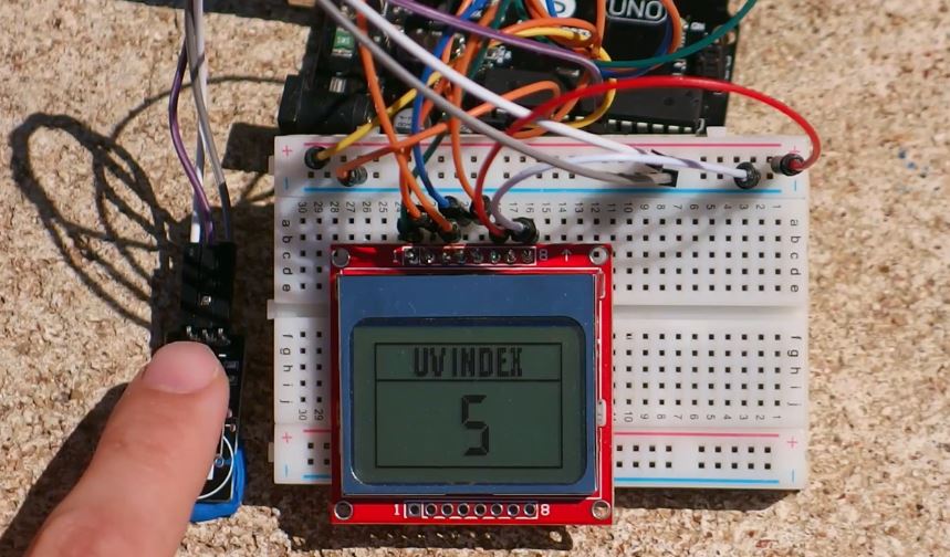
Today, we will build a UV meter using the Arduino and the ultraviolet sensor (UVM30A) with a Nokia 5110 LCD display as the display for the meter. The Nokia 5110 is used to display the UV index which is an international standard unit for the intensity of ultraviolet rays from the sun being experienced in a particular place and at a particular time.
Arduino UV Meter using the UV30A Ultraviolet Sensor – [Link]
Ultraviolet rays, also known as UV for short are rays emitted by sun. Due to the depletion of the ozone layer, these rays tend to get to extreme levels that could lead to sunburns etc for those under it, that’s why daily and hourly forecast of the UV index is always available to help people keep track and stay safe. For monitoring purposes, why not own a personal UV meter?
Today, we will build a UV meter using the Arduino and the ultraviolet sensor (UVM30A) with a Nokia 5110 LCD display as the display for the meter. The Nokia 5110 is used to display the UV index which is an international standard unit for the intensity of ultraviolet rays from the sun being experienced in a particular place and at a particular time.
UV Meter
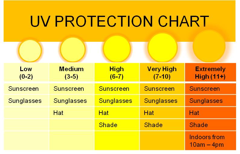
The Purpose of measuring the UV index in a particular place and at a particular time is to prevent people from the dangers caused by high UV index rays as it could lead to things like sunburn etc. It is also measured to guide people, so they can take adequate protective measures, like the use of sunscreens, sunglasses, hats etc on a day out. A UV Protection chart which tries to match the UV index with the adequate protective devices is shown below.
It can be seen from the chart that when UV level is extremely high it is advised to stay indoors, the reason for this is, the UV index indoors is mostly zero. This means that when testing the device we are about to build, you should take it outside as shown in the image below, as the value won’t change if you test indoors.
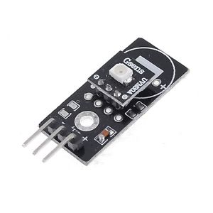
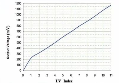
The UVM30A UV sensor which we will use for this tutorial is a low-cost analog sensor with an almost linear output. This means the output of the sensor increases or decreases with a proportional increase or decrease in UV radiation respectively. A graph of the sensor’s output (in mV) against the UV index, culled from the sensor’s datasheet to describe its linearity is shown below.
Linearity between UV index and output voltage from sensor
It is a simple three pin sensor consisting of the VCC, GND and the analog signal output.
With that said, let get down to business.
Required Components
The following components will be needed to build this project.
As usual, the exact components used for this tutorial can be bought by following the link attached to each of them.
Schematics
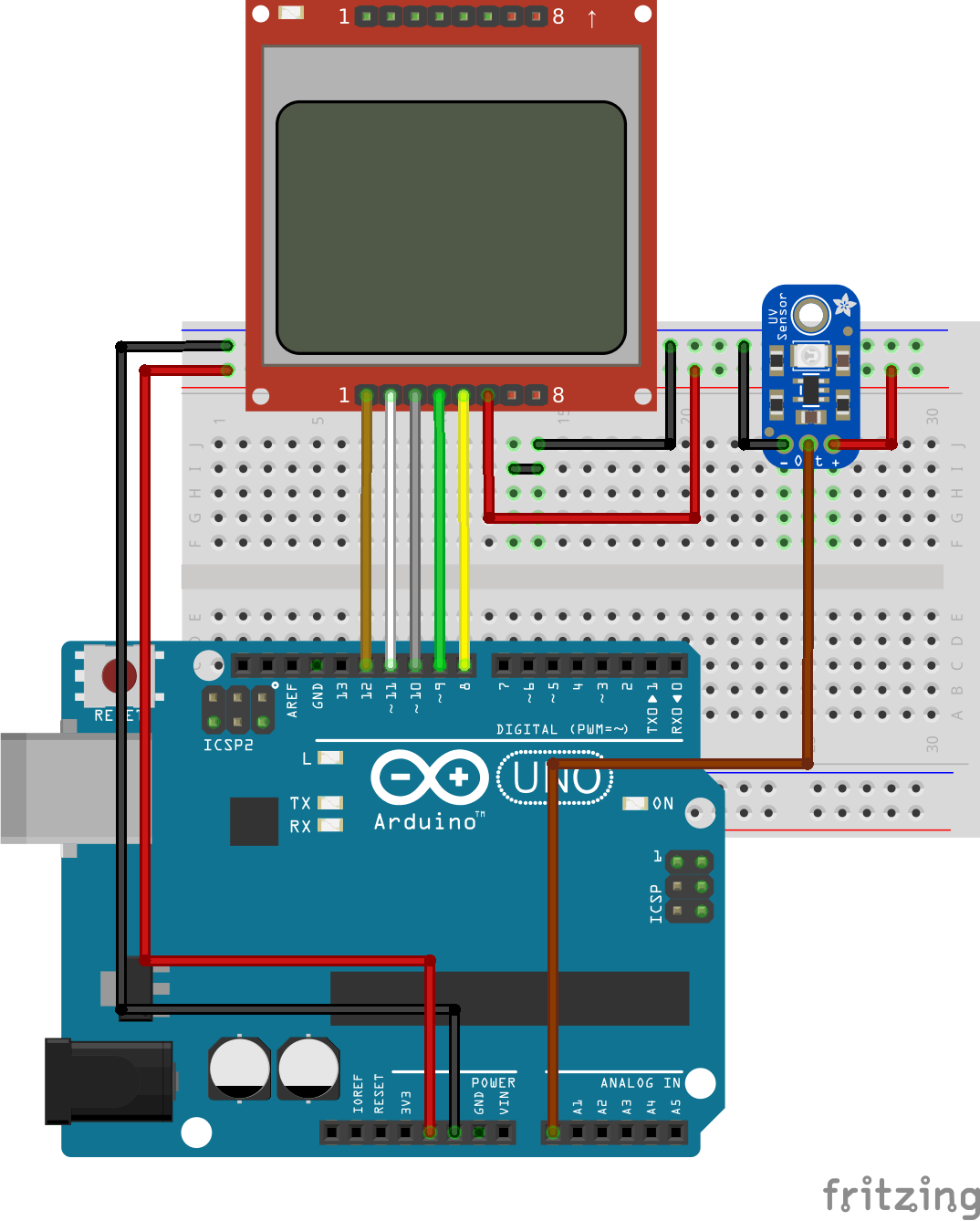
With all the components at the ready, let’s wire it up according to the schematics below;
Schematics
Connecting the N0kia 5110 LCD to the Arduino is an art that we have perfected over several tutorials, an example of which can be found here, but for the purpose of this tutorial, we will still include the pin map so you can easily connect it if following that schematic is a little bit difficult. Alongside the pin map for the LCD is the pin map for connecting the UV sensor to the Arduino.
Double check the connections to confirm everything is okay before proceeding to the code.
Code
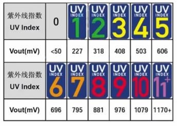
The code for this project is fairly simple, we are using only one library which is the Nokia 5110 LCD library to communicate with the LCD. The library can be downloaded from this link. The basic operation of the code is to read the analog pin 0 (A0) to which our sensor’s output is connected and convert it into mV so we can compare with the values in the UV index table and calculate the UV Index at that particular place and time. After the calculation and the UV index determination, the index is displayed to the user via the Nokia 5110 LCD. The UV index table for comparison is shown in the image below.
Index table to match mV to UV index
As usual, we will break the code into small chunks and explain before giving the full code. The code is also attached in the zip file available at the download section, located at the end of this tutorial.
To jump in, the first thing we do in the code is import the Nokia 5110 LCD library which is needed for the display.
//////////////////////////////////////////////
  //            Arduino UV Meter              //
 //            with NOKIA 5110 LCD           //
//           http://www.educ8s.tv           //
/////////////////////////////////////////////

#include <LCD5110_Graph.h>
After importing the library and making some comments on what the project is all about, we move to declare other variables and constants which will be used in the code.
With that done, we move to the setup function. The first thing we do is initialize the LCD, then we set the fonts for the display, clear the screen with lcd.clrScr(), after which we draw the splash bitmap. The process of creating the splash bitmap and inserting it into your Arduino code was covered in details in one of our previous tutorials which can be found here.
After the drawBitmap command, we update the LCD to reflect changes and we delay for 3000ms to ensure the splash stay long enough on the screen to be seen.
 lcd.update();
 delay(3000);

}
With the setup done, we move into the loop() function.
Here we call the readSensor function, which reads the value from the UV sensor, converts it into mV and compares it with the Index table to get the UV index match for the mV value that was read in.
void loop() {

 int stringLength = 0;

 UV = readSensor();
Next, we clear the screen and draw the UI into which the index will be inserted.
lcd.clrScr();
lcd.drawBitmap(0, 0, ui, 84, 48);
With the UI drawn, we then calculate the length of the index and it is displayed using the printUV function after which the LCD update command is called.
Connect the Arduino board to your computer, launch the IDE and paste the code into it. Don’t forget to add the UI and the Splash files to the Arduino sketch folder for the code before uploading as this may bring up errors. The splash and UI files are part of the files in the zip file under the downloads section.
Demo
Upload the code to your board and take it outside to measure the UV intensity in your area. It was a very sunny day in Greece at the time this tutorial was written.
That’s it for this tutorial guys, as usual, you can drop comments and questions via the comment section.
Till next time.
The video tutorial for this project is available on youtube here.
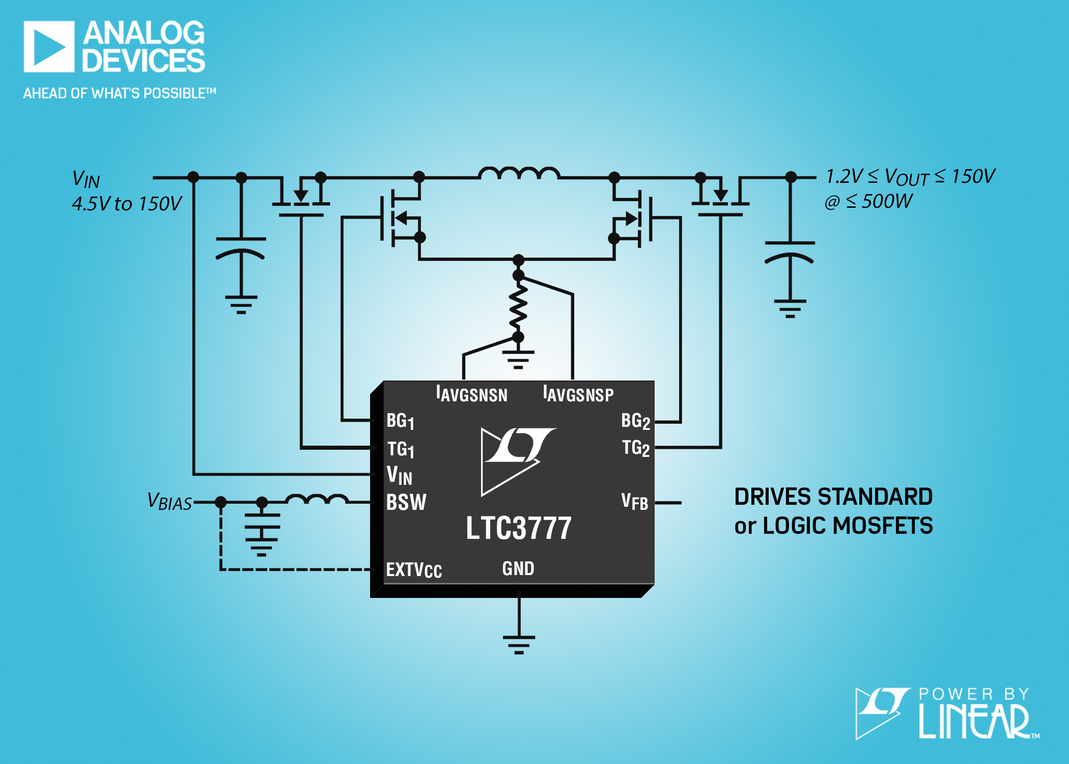
Analog Devices announces the Power by Linear™ LTC3777, a 150V high efficiency (up to 99%) 4-switch synchronous buck-boost DC/DC controller, which operates from input voltages above, below or equal to the regulated output voltage. Its 4.5V to 150V input voltage range operates from a high input voltage source or from an input that has high voltage surges, eliminating the need for external surge suppression devices, ideal for transportation, industrial and medical applications.
To prevent high on-chip power dissipation in high input voltage applications, the LTC3777 integrates a low quiescent current high efficiency switching bias supply for its internal power consumption. The output voltage of the LTC3777 can be set from 1.2V to 150V at output currents up to tens of amps, depending on the choice of external components. Output power up to 500W can be delivered with a single device. Higher powers can be achieved when multiple circuits are configured in parallel. The LTC3777’s powerful 1.5Ω N-channel MOSFET gate drivers can be adjusted from 6V to 10V, enabling the use of logic-level or standard-threshold MOSFETs.
The LTC3777 employs a proprietary current mode control architecture for constant frequency in buck, boost or buck-boost modes. The operating frequency can be synchronized to an external clock from 50kHz to 600kHz, while an input/output constant current loop provides support for battery charging and overload protection. The user can select either forced continuous mode or discontinuous mode to maximize light load efficiency. Additional features include seamless transfers between operating regions, a power good output voltage monitor, adjustable soft-start and input overvoltage lockout, and output voltage disconnect during shutdown.
The LTC3777 is available in a 48-lead e-LQFP package with pin skipping for high voltage spacing. Extended and industrial versions are available from –40 to 125°C.
Summary of Features: LTC3777
4-Switch Synchronous Current Mode Buck-Boost Architecture
Operation with Input Voltages Above, Below or Equal to the Output Voltage
4.5V to 150V Input Voltage Range
1.2V to 150V Output Voltage Range
Up to 99% Efficiency
Integrated Switching Bias Supply
Input or Output Average Current Limit
Adjustable 6V to 10V MOSFET Gate Drivers
Compatible with Logic-Level or Standard-Threshold NMOS
500 Watts Output Power Capable with a Single Device
Fixed Synchronizable Operating Frequency from 50kHz to 600kHz
Output Voltage Disconnect from VIN During Shutdown
Adjustable Soft-Start
±1% Reference Voltage Accuracy over -40°C to 125°C
48-Lead e-LQFP Package with High Voltage Pin Skipping
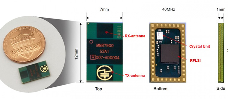
The Socionext MN87900 from Socionext is a powerful and low-power single-chip microwave sensor at 24GHz with sophisticated sensing capabilities like motion detection, speed and direction detection and so many, that can quickly find applications in the Internet of Things sensing applications.
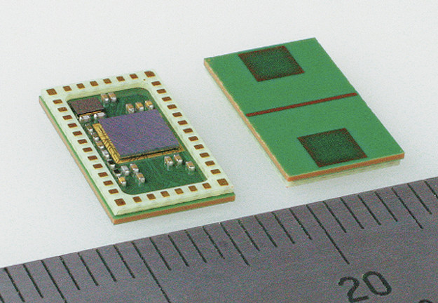
Socionext MN87900
Unlike PIR sensors like the popular HR-SR501 that can detect motion to about 3 meters at about 120 angles and based on the concept of detecting infrared energy emitted by an object while attempting to determine if it’s a motion or not, the Socionext MN87900 is a microwave sensor that sends out microwave signals and detects the bounce back signals to decide if it’s a motion or not. Microwave sensor uses what we call the Doppler’s Effect concept.
SocioNext MN87900 is a 24 GHz and very tiny, measures about 12mm x 7mm x 1mm making it ideal for the small size requirement in the most Internet of Things application and other applications in the areas of smart-home, automotive or driver assistance systems, medical applications, and many more. Based on a single-chip radio frequency IC (RFIC) that offers a multi-mode sensing capability for detecting stationary or moving objects and measuring the distance and direction of movement, including whether an object is approaching or leaving. This multi-mode sensor capability gives the device ability to re-adapt its functionality to different case scenario without making any single hardware changes.
The RFIC can be used to sense very slow movements (like breathing and heartbeats), and even detect the movement of multiple objects within a 160-degree radius to a distance of about 8 meters away. With slight modification, the RFIC can reach a range of up to 30 meters.
Apart from having powerful sensing capabilities, it is also power friendly. During continuous operation, the sensor can take up to 500mW, but this can be reduced to an intermittent operation where for example, during a one-sixth burst, the sensor can take about 80mW, a very drastic reduction in power. The MN87900 can pass through fabric or resin like materials, and unlike camera-based people detecting applications, the MN87900 doesn’t need to capture or display images to identify people or objects which is handy for privacy-concerned applications.
The MN87900 supports SPI as a form of interface to microcontroller system. Along with the hardware, a simple API system was developed to support the designs of CW, FSKCW, and FMCW mode capabilities to provide distance, direction, and relative velocity.
The following are the SocioNext MN87900 key specifications:
Sensing Modes – CW, FSKCW, FMCW (moving or stationary)
Detection
Motion direction – approaching or leaving
Motion speed – up to 200 km/h
Range – 0.15 to 8 meters 80°@-3dB, expandable to 30 meters
Variable frequency width – 24.15±0.1 GHz
Host Interface – SPI
High sensitivity – -110dBm
Transmission Power: 0.8mW
Fast frequency pull-in: 100 µs
Automatic adjustment: Built-in initial adjustment function (e.g. adjustment of RC filtering)
Power supply voltage: 2.5V
Current consumption: 200mA
Module size: 12mm x 7mm x 1mm
Weight – 145 mg
Temperature Range – -40°C to 85°C
The module pricing is currently not available, and more information about the product can be found here.
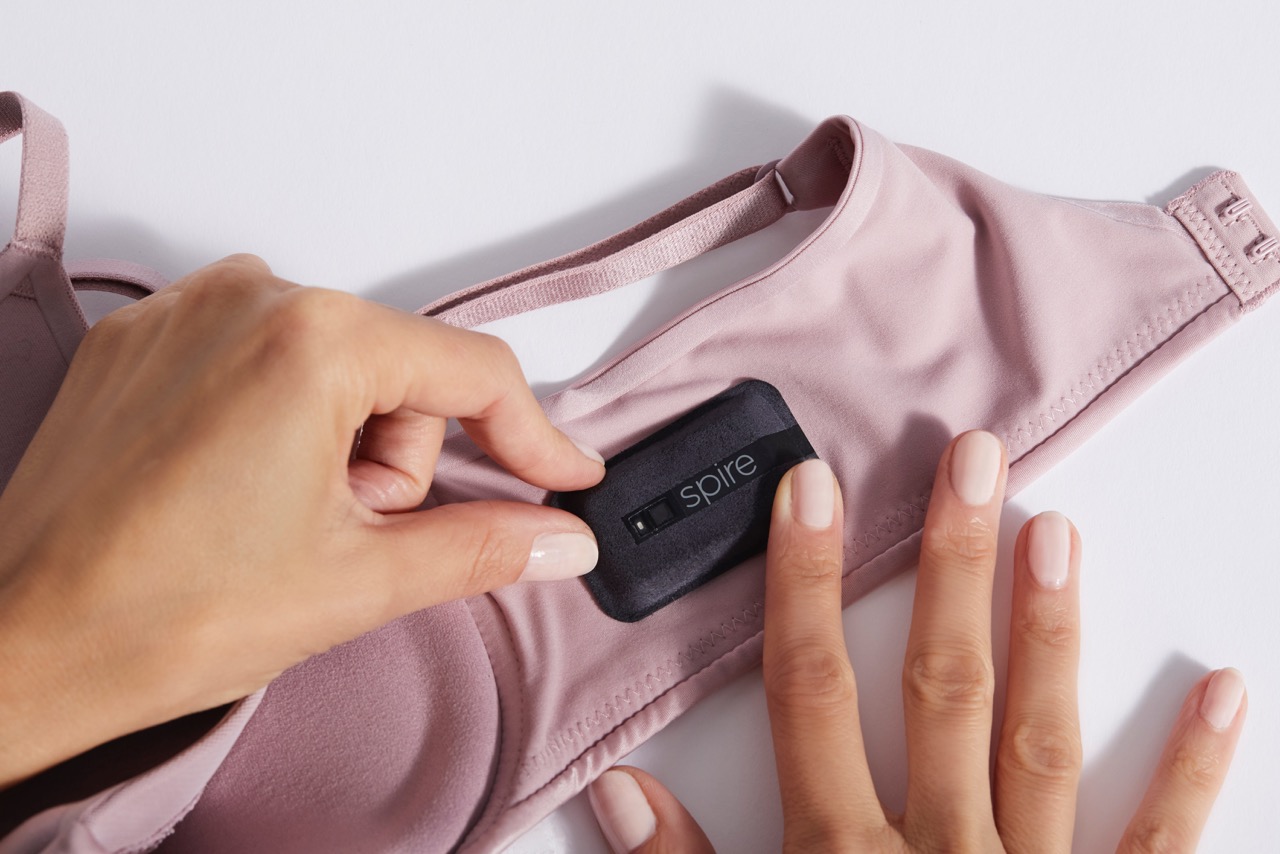
CAP-XX (LSE:CPX), developer of supercapacitors that deliver peak power to support or replace batteries, today announced that Spire has incorporated CAP-XX Thinline supercapacitors into the new Spire Health Tag to provide the peak power needed for delivering real-time wellness vibration alerts to consumers. Offloading this peak power role to the thin, flat supercapacitor allows Spire to keep the battery small to achieve the ultra-thin form factor of its new wearable fitness biosensor that attaches to clothes once, can be washed as normal, and needs no charging. Press release: https://www.webwire.com/ViewPressRel.asp?aId=216739. Spire will demonstrate its Spire Health Tag at CES booth #43706. Continue reading “CAP-XX Thinline Supercapacitors Power Vibration Alerts”
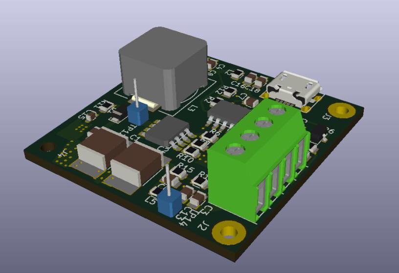
Mark Smith @ surfncircuits.com has a detailed explanation on building a Nixie power supply, able to produce 170V from a 5V source. The article is spitted in 3 parts, with part two presenting the results and performance and part 3 discussing PCB design.
Nixie Tubes are cool retro looking decimal digit displays useful for many modern DIY projects like the venerable Nixie Tube digital clock. The Nixie Tube, invented in the 1950’s, can provide a great fusion of old display technology with new innovations. Unfortunately, one major difficulty in using them is that Nixie tubes need voltages up to 170V to energize. While this voltage can be made several ways, a convenient way and the subject of this blog is to generate this voltage from a 5v supply. This will allow the use of the same 5v supply used to power the Raspberry Pie, an ESP8266, an Arduino or another microcontroller that controls the display or IOT project.
Designing a Small Footprint, Low Profile 5v to 170v Nixie Tube Power Supply – [Link]
A synchrotron is a particular type of cyclic particle accelerator which is used to accelerate quantum level charged particles at a very high velocity, traveling around a fixed closed-loop path.
It is one of the first accelerator concepts to enable the construction of large-scale facilities because they are very efficient in beam focusing, bending, and splitting the beam into different components. The most powerful modern particle accelerators such as Large Hadron Collider (LHC) in Switzerland uses bigger versions of the synchrotron design.
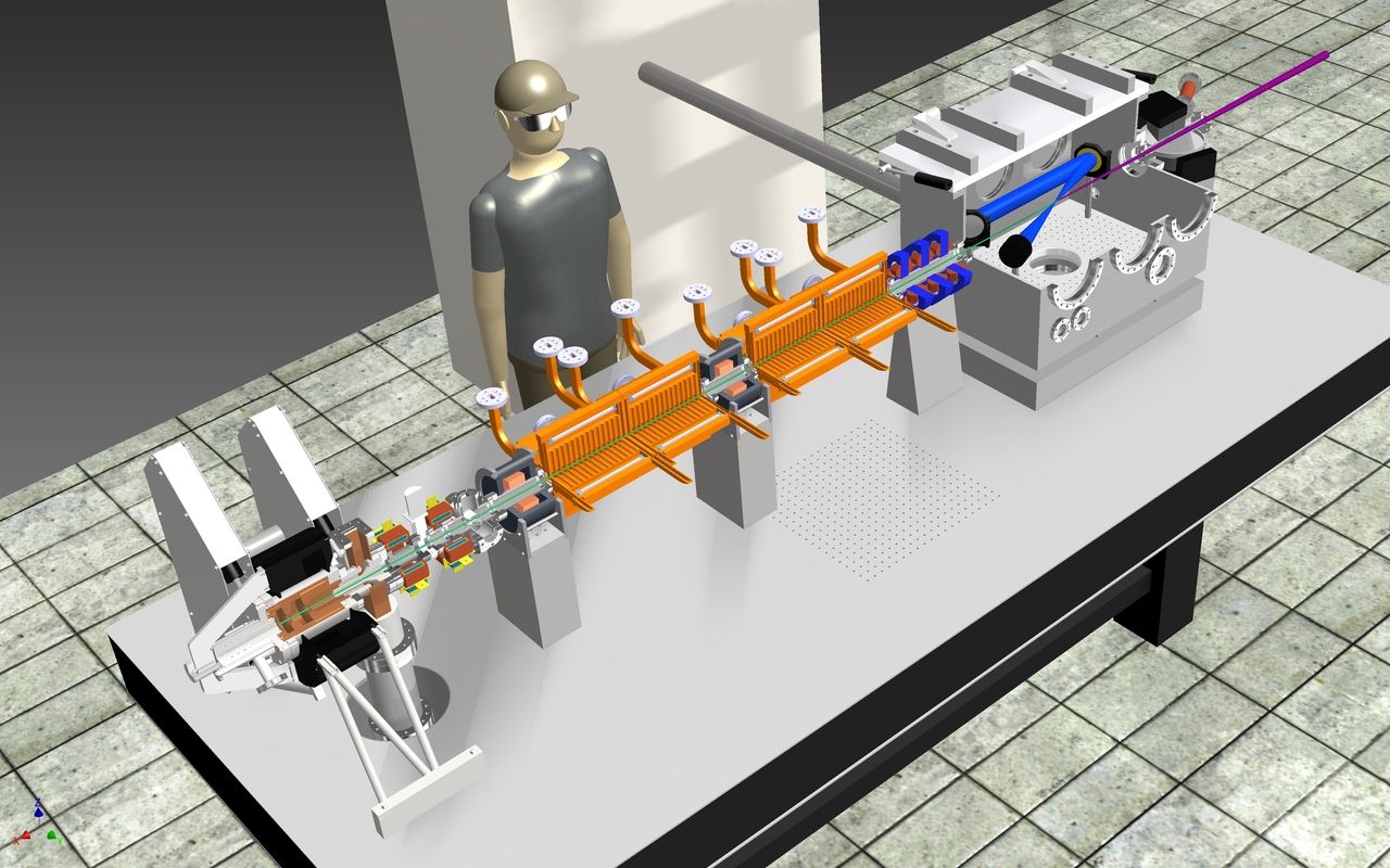
Scientists design mini synchrotron that is only 4m long
A synchrotron is mainly used for the production of X-ray in many medical, engineering or industrial fields. Researchers at Eindhoven University of Technology and Delft University of Technology will build and develop a new scaled down version of a synchrotron which will even fit on a tabletop. The intensity of the X-ray radiation of this device will be just as powerful as the larger ones. “Smart*Light” is the name of this new synchrotron which they officially took under research on 23rd January.
With Smart*Light, the consortium wants to build a ‘scaled down synchrotron‘. A compact and tunable X-ray source which is less than 4 meters long, which can be used in any lab. The potential of application for such a device is huge in medical diagnostics, high-tech industries, aircraft, car, and ship manufacturing.
Using Smart*Light there is the opportunity to analyze the chemical composition of old or new artworks layer by layer. This does not only have importance for conservation but, also for research into authenticity too.
The operation of this revolutionary X-ray source is based on the physical concept where X-rays are produced from collisions between LASER light and accelerated electrons. The theory is known as Inverse Compton Scattering, and has already been recognized for decades, but only recently has the necessary technology been modern enough to be developed.