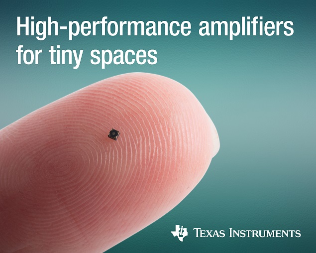
Aimee Kalnoskas @ eeworldonline.com discuss about TI’s tiny OPAMP and comparators.
Texas Instruments introduced the industry’s smallest operational amplifier and low-power comparators at 0.64 mm2. As the first amplifiers in the compact X2SON package, the TLV9061 op amp and TLV7011 family of comparators enable engineers to reduce their system size and cost, while maintaining high performance in a variety of Internet of Things (IoT), personal electronics and industrial applications, including mobile phones, wearables, optical modules, motor drives, smart grid and battery-powered systems.
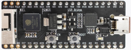
ESP32-PICO-KIT V4 is a mini development board produced by Espressif. At the core of this board is the ESP32-PICO-D4, a System-in-Package (SIP) module with complete Wi-Fi and Bluetooth functionalities. Comparing to other ESP32 chips, the ESP32-PICO-D4 integrates several peripheral components in one single package, that otherwise would need to be installed separately. This includes a 40 MHz crystal oscillator, 4 MB flash, filter capacitors and RF matching links in. This greatly reduces quantity and costs of additional components, subsequent assembly and testing cost, as well as overall product complexity.
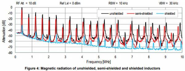
Application note form Würth Elektronik about EM radiation radiated from inductors in DC-DC converters.
This Application Note focuses on the Electro-Magnetic (EM) radiation behavior of power inductor(s) in DC-DC converters, which is dependent on several parameters such as ripple current, switching frequency, rise & fall time of a switching device, the core material and its permeability and suggests several design tips to mitigate these EMI effects.
The behavior of electro-magnetic radiation of power inductors in power management – [Link]
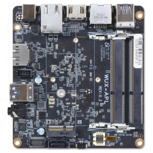
Portwell’s WUX-3350 small form factor (SFF) embedded system board features the Intel Celeron and Pentium processor series, supporting the low power Intel Gen9 graphics engine with up to 18 execution units for enhanced 3D graphics performance and greater speed for 4K encode and decode operations.
The WUX-3350 series (WUX-3350, WUX-3455, WUX-4200) of 4×4-inch mini PC board (Intel® NUC board form factor) is designed with Intel® Pentium® processor N4200, and Intel® Celeron® processor N3350/J3455 (codenamed Apollo Lake), and features dual-channel DDR3L up to 8GB, Gigabit Ethernet, M.2 expansion interface, and support for wide input voltage range from 12V to 19V. The WUX-3350 4×4-inch mini PC board series can be an ideal building block for designing ultra-compact embedded computing systems with configurability for an extensive array of applications.
IoT which translates to the Internet of Things has been a significant buzz for the last five years while disrupting major Industries (from Agriculture, Energy, Healthy, Sports and several others).
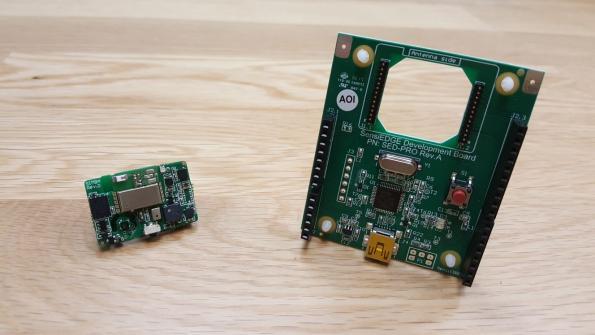
SensiBLEduino Development Kit
IoT adoption has seen rapid development in the makers’ world, with different makers and manufacturers producing various forms of boards, chips, software to facilitate quick IoT development. Boards like ESP8266 from Espressif System is used for rapid prototyping and a low-cost choice for Wi-Fi-based IoT applications. Israeli based IoT firm SensiEdge has launched the SensiBLEDuino, an off-the-shelf, hardware-ready development kit based on the open-source Arduino for rapid prototyping of IoT applications.
SensiBLE is a full fledge customizable solution for those wanting to design IoT products. It helps to fasten development with a variety of sensors onboard, along with Bluetooth LE 4.1 capabilities and a low-power ARM® 32-bit Cortex®-M4 CPU with FPU. Some of the main challenges when embarking on IoT product development are; what platform will I use? What sensors are available to achieve my goal(s)? How do I handle connectivity? What about the Cloud Platform to use, and so on. Developers or product designer always result in the use of several boards or modules to achieve this while also increasing the time to bring the product to life. The SensiBLE kit removes most of these fears; it combines hardware and software in tiny form factor to allow developers get their product to market quickly at lower development costs. Continue reading “SensiBLEduino – A full fledge ‘hardware-ready’ development kit for IoT and supports Arduino”
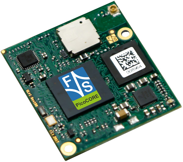
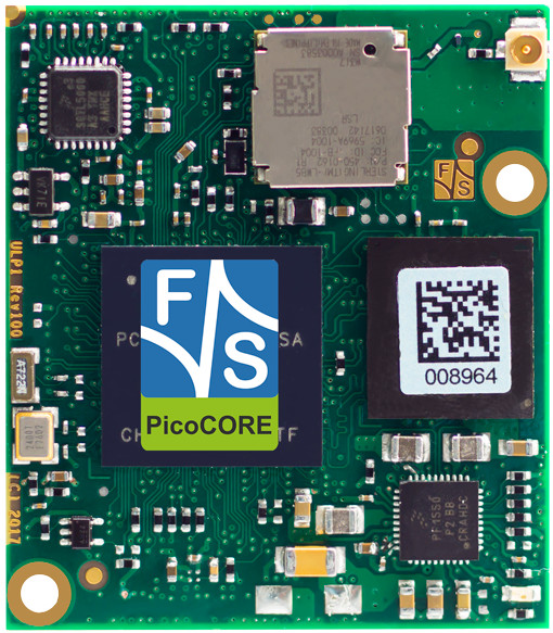
F&S announced their tiny PicoCore MX7ULP module, which is able to run Linux or FreeRTOS on an NXP i.MX7 SoC. The board comes with up to 32GB eMMC plus optional WiFi/BT and extended temperature support. The new board measures only 40 x 35mm and will be presented on Embedded World (Feb. 27-Mar. 1) with expected shipment in the third quarter 2018. The PicoCore module doesn’t have an edge connector, instead interfaces with a 2x 80-pin Hirose DF40C plug connectors.
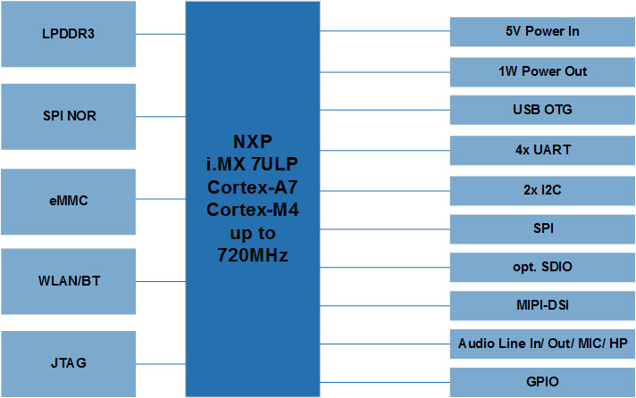
PicoCore MX7ULP Block Diagram
The PicoCore MX7ULP ships with up to 1GB LPDDR3 RAM, 64MB SPI NOR flash, up to 32GB eMMC, and an optional SD slot. There’s also an option for a wireless module with 802.11b/g/n and Bluetooth 4.1 LE. For display, you get a MIPI-DSI interface that is accompanied with I2C-based resistive and capacitive touch support.
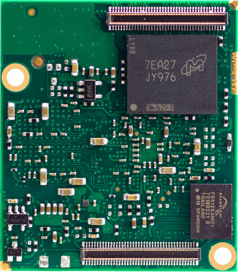
PicoCore MX7ULP, front and back
Additional I/O includes USB OTG, SPI, 2x I2C, 33x general purpose DIO, audio interfaces, and 2x UARTS. The 10-gram board runs on 5V DC power (or a 4.2V battery) and consumes a typical 1W. For more information, please visit F&S Elektronik Systeme’s PicoCore MX7ULP announcement and product page.
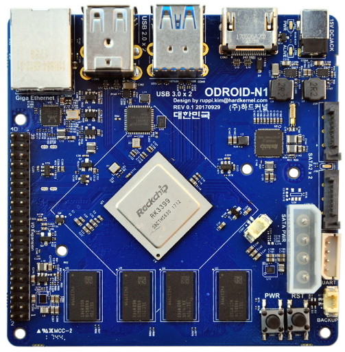
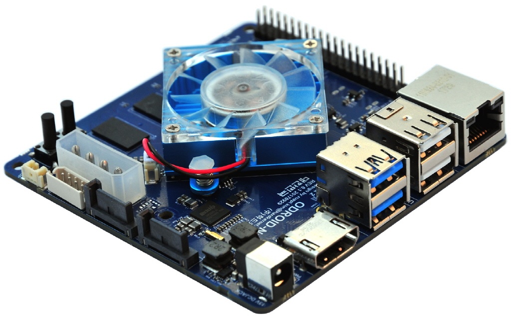
The Rockchip RK3399 has revolutionized the open-spec single-board computer world. Hardkernel’s new Odroidproject has made the multi-core SoC RK3399 to firm it’s grip further. Recently Hardkernel released images, specs, and extensive benchmarks on a prototype for its storage-oriented new Odroid-N1 board. The boards can be expected to launch for about $110 in May or June this year.
New Odroid-N1 based on Rockchip’s RK3399
The 90x90x20mm SBC is highlighted for offering dual channel SATA III interfaces and 4GB DDR3-1866 dual-channel RAM. The Odroid-N1 can run Android 7.1, as well as Ubuntu 18.04 or Debian 9 with Linux Kernel 4.4 LTS. This new board can also be open source as its previous flagship Odroid-XU4.
The RK3399 features two Cortex-A72cores that are clocked at up to 2.0GHz, as well as four Cortex-A53 cores, which are clocked at 1.5GHz. (Some other RK3399 boards have listed 1.42GHz.) This board also includes a high-end ARM Mali-T864 GPU. Hardkernel’s benchmarks have shown the hexa-core RK3399 based Odroid-N1 is running significantly faster on most tests, beating the Odroid-XU4’s octa-core (4x Cortex-A15, 4x -A7).
The Odroid-N1 is equipped with a GbE port, 2x USB 3.0 ports, and 2x USB 2.0 ports, HDMI 2.0 port for up to 4K Video output. There’s also a 40-pin GPIO header. The Power input is mentioned at 12V/2A, although attaching two 3.5inch HDD will require a 12V/4A PSU. As with the other RK3399 boards, there are no hopes of Raspberry Pi add-on compatibility.
The RK3399 has powered many similar SBCs previously. The first major RK3399 SBC was Firefly’s Firefly-RK3399, soon followed by Vamrs’ similarly open source Rockchip RK3399 Sapphire. More recently we’ve seen Shenzhen Xunlong’s Orange Pi RK3399.
The RK3399 is also finding key roles among many commercial boards. We just saw Aaeon take the leap with its OEM-oriented RICO-3399 PICO-ITX SBC. Earlier, Videostrong announced a VS-RD-RK3399 SBC.
ODROID-N1 key features:
Rockchip AArch64 RK3399 Hexa-core processor
Dual-core ARM Cortex-A72 2Ghz processor and Quad-core ARM Cortex-A53 1.5Ghz processor, big-LITTLE architecture
Mali-T860MP4 GPU, support OpenGL ES1.1/2.0/3.0, OpenCL 1.2
4Gbyte DDR3-1866 RAM, Dual channel interface for 64bit data bus width
2 x SATA3 port, native SATA implementation via PCIe-gen2 to SATA3 interface
eMMC 5.0 (HS400) Flash storage and a UHS capable micro-SD slot.
2 x USB 3.0 host port
2 x USB 2.0 host port.
Gigabit Ethernet port
HDMI 2.0 for 4K display
40-Pin GPIO port
OS: Ubuntu 18.04 or Debian Stretch with Kernel 4.4 LTS, Android 7.1
Size: 90 x 90 x 20 mm approx. (excluding cooler)
Power: 12V/2A input (Attaching two 3.5inch HDD requires a 12V/4A PSU)
Price: US$110 (To be adjusted based on DRAM market price changes)
Mass production schedule: TBD
More information is available in the Odroid-N1 announcement.
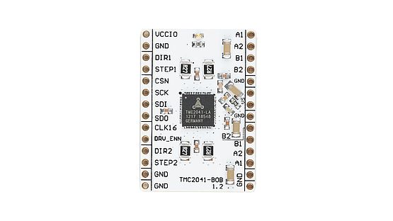
The TMC2041 breakout board is a development board with the dedicated TMC2041-LA chip. It is designed to give users the chance to rapidly prototype their applications – making it possible to immediately check how the motor performs with TMC chips while developing the application’s software. Further information on the chip can be found here:
The TMC2041-LA provides an integrated motor driver solution for 3D-Printing, Cameras, Scanners and other automated equipment applications. The device has an integrated microstepping indexer, the sensorless stall detection technology stallGuard2™, the sensorless load dependent current control coolStep™ and is intended to drive a bipolar stepper motor. The output driver block consists of low RDSon N-Channel power MOSFETs configured as full H-bridges to drive the motor windings. The TMC2041 is capable of driving up to 1.5A of current from each output (with proper heatsinking). TMC2041 is designed for a supply voltage of 5…26V. The device has a SPI interface for configuration and diagnostics and a step and direction interface.
A data logger is an electronic device or instrument that records data over a period of time. It allows the user to record time or location stamped data which can be viewed at a later time or real time.
Irrespective of the type of data being logged or the kind of data logger, these devices usually contain two main units, the sensor unit and the storage/communication unit. The sensor unit may involve the use of an external instrument or a sensor embedded within the device. Increasingly, but not entirely, data logging devices are becoming more based on micro processors and microcontrollers, which has opened up a whole new level of data gathering and storage.
For today’s tutorial, our focus will be on building an Arduino based data logger that reads the temperature of the environment every few minutes and saves the data in a micro sd card.
The Project is based on the Arduino nano and the DS3231 RTC Module which has a temperature sensor and a real time clock on board.
Required Components
The following components are required to build this project:
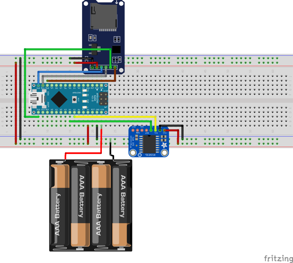
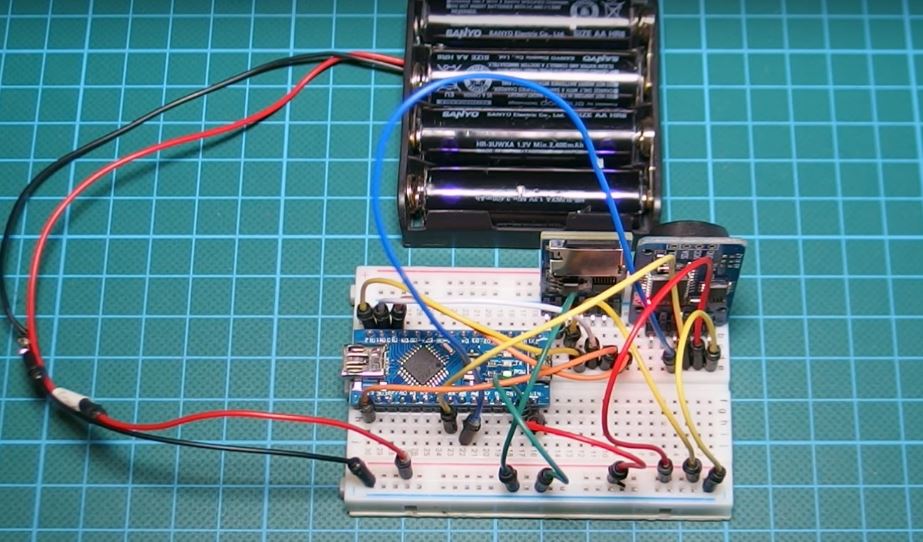
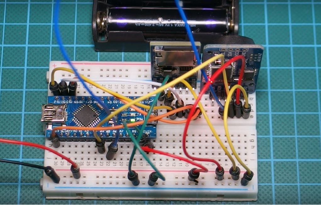
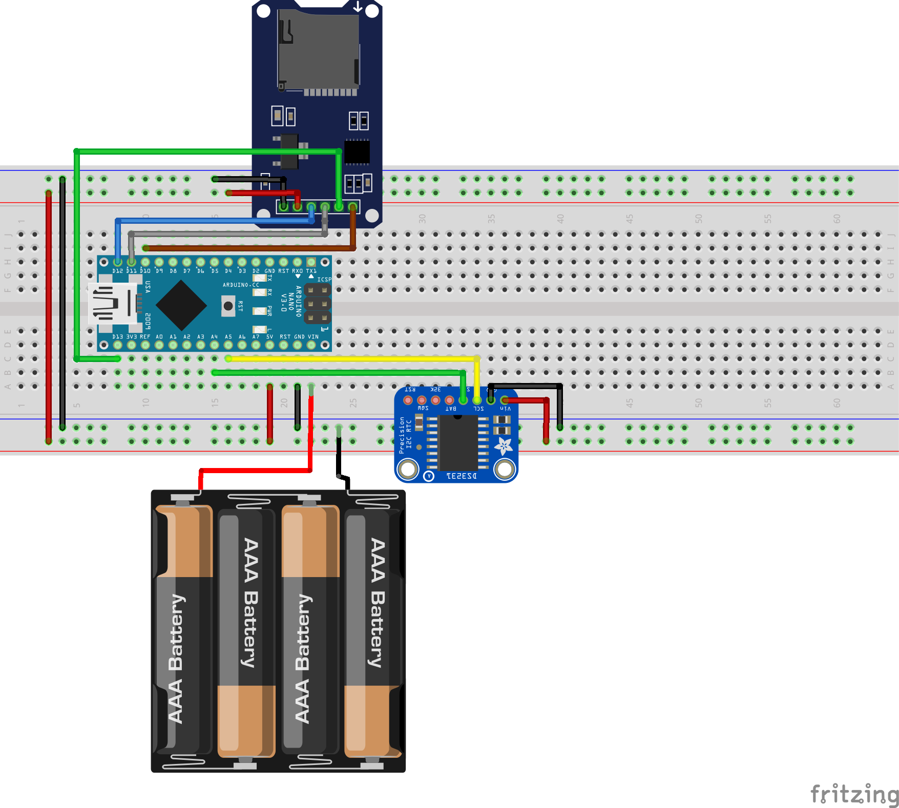
Connect the components as shown in the circuit diagram below.
Schematics
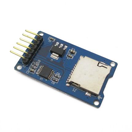
The data logger is made up of the Arduino Nano, the Ds3231 RTC Module, and a micro SD card module. The micro SD card module communicates with the Arduino over SPI as explained in a detailed tutorial here, while the DS3231 module communicates with the Arduino over I2C. A detailed tutorial on the DS3231 module can also be found here.
To simplify the connection further, a pin map of the connections in the schematics is done below.
A connection between Arduino and Micro SD card Module:
With the connections all done, we can then move to write the code for this project.
Code
To better understand this project, it is advised that you take a look at two of our previous projects that talked about DS3231 RTC module, and the Micro SD card module.
To jump into writing the code, its important before proceeding to totally understand what you want it to do. For this project we will measure temperature, and storing the data alongside the time at which it was read, delimited by comma, in a text file on a SD card. The goal will be to remove the card after a while and insert it into a computer, to import the data into Microsoft’s Excel software to plot and perform other analysis on the data.
As usual, the first thing we do in our code is to include the libraries that will be used. For this project, we will be using the rtc_ds3231 library attached in the zip file which is available in the download section of this post, the wire.h library, the SD.h library, and the SPI.h library.
    /////////////////////////////////////////////////////////////////
   //            Arduino Simple Data Logger             v1.03     //
  //         Get the latest version of the code here:            //
 //         http://educ8s.tv/arduino-data-logger-project        //
/////////////////////////////////////////////////////////////////

#include <Wire.h>
#include "ds3231.h"
#include <SD.h>
#include <SPI.h>
Next, we declare our variables. The first variable is the maximum buffer size BUFF_MAX 128 after which, we declare the pin to which is the Chipselect pin of our sd card module connected to the Arduino, which is D10. We next create an object file, then declare the variable to store temperature, time, and date, followed by an integer to serves as ID for the entries.
#define BUFF_MAX 128

int CS_PIN = 10;

File file;

String temperature;
String timeString;
String dateString;

int entryId = 0;
Still on declaration, we declare an array to hold time, and set the amount of milliseconds the device has to wait before logging the next data. This could help preserve the battery life of the device in the long run asides other things.
uint8_t time[8];
char recv[BUFF_MAX];
unsigned int recv_size = 0;
unsigned long prev, interval = 1000;
We then move to the setup function.
We start by starting serial communication and enabling wire, after which we move to initialize the SD card module followed by the DS3231 module.
with that done, when running the code for the first time, there will be a need to set the time. The next line of code is used to set the time. It is entered in this order: T”seconds””minutes””timeinhours””dayoftheweek””dayofthemonth””month””year”
Do note the quotes are not included, it was just used for explanation.
parse_cmd("T302410426032015",16); //Set time
}
After running this code for the first time, it should be commented out before uploading to deploy the system.
With the Void Setup out of the way, we now move to the void loop() function. The void loop function majorly contains commands to get the temperature and date and save it on the sd card.
void loop()
{
String logEntry;
char in;
char buff[BUFF_MAX];
unsigned long now = millis();
// Log data once in a while
if ((now - prev > interval) && (Serial.available() <= 0)) {
getTime();
getTemperature();
logEntry = createLogEntry();
writeEntryToFile(logEntry);
prev = now;
}
if (Serial.available() > 0) {
in = Serial.read();
if ((in == 10 || in == 13) && (recv_size > 0)) {
parse_cmd(recv, recv_size);
recv_size = 0;
recv[0] = 0;
} else if (in < 48 || in > 122) {; // ignore ~[0-9A-Za-z]
} else if (recv_size > BUFF_MAX - 2) { // drop lines that are too long
// drop
recv_size = 0;
recv[0] = 0;
} else if (recv_size < BUFF_MAX - 2) {
recv[recv_size] = in;
recv[recv_size + 1] = 0;
recv_size += 1;
}
}
}
Other functions in the code are functions that were called within the void loop.
The full code for the project is given below.
/////////////////////////////////////////////////////////////////
// Arduino Simple Data Logger v1.03 //
// Get the latest version of the code here: //
// http://educ8s.tv/arduino-data-logger-project //
/////////////////////////////////////////////////////////////////
#include <Wire.h>
#include "ds3231.h"
#include <SD.h>
#include <SPI.h>
#define BUFF_MAX 128
int CS_PIN = 10;
File file;
String temperature;
String timeString;
String dateString;
int entryId = 0;
uint8_t time[8];
char recv[BUFF_MAX];
unsigned int recv_size = 0;
unsigned long prev, interval = 1000;
void setup()
{
    Serial.begin(9600);
    Wire.begin();

    initializeSD();

    DS3231_init(DS3231_INTCN);
    memset(recv, 0, BUFF_MAX);
//parse_cmd("T302410426032015",16); //Set time
}
void loop()
{
    String logEntry;
    char in;
    char buff[BUFF_MAX];
    unsigned long now = millis();

    // Log data once in a while
    if ((now - prev > interval) && (Serial.available() <= 0)) {
      getTime();
      getTemperature();
      logEntry = createLogEntry();
      writeEntryToFile(logEntry);
      prev = now;
    }

    if (Serial.available() > 0) {
        in = Serial.read();

        if ((in == 10 || in == 13) && (recv_size > 0)) {
            parse_cmd(recv, recv_size);
            recv_size = 0;
            recv[0] = 0;
        } else if (in < 48 || in > 122) {;       // ignore ~[0-9A-Za-z]
        } else if (recv_size > BUFF_MAX - 2) {   // drop lines that are too long
            // drop
            recv_size = 0;
            recv[0] = 0;
        } else if (recv_size < BUFF_MAX - 2) {
            recv[recv_size] = in;
            recv[recv_size + 1] = 0;
            recv_size += 1;
        }

    }
}
void parse_cmd(char *cmd, int cmdsize)
{
uint8_t i;
uint8_t reg_val;
char buff[BUFF_MAX];
struct ts t;
// TssmmhhWDDMMYYYY aka set time
if (cmd[0] == 84 && cmdsize == 16) {
//T355720619112011
t.sec = inp2toi(cmd, 1);
t.min = inp2toi(cmd, 3);
t.hour = inp2toi(cmd, 5);
t.wday = inp2toi(cmd, 7);
t.mday = inp2toi(cmd, 8);
t.mon = inp2toi(cmd, 10);
t.year = inp2toi(cmd, 12) * 100 + inp2toi(cmd, 14);
DS3231_set(t);
//Serial.println("OK");
} else if (cmd[0] == 49 && cmdsize == 1) { // "1" get alarm 1
DS3231_get_a1(&buff[0], 59);
//Serial.println(buff);
} else if (cmd[0] == 50 && cmdsize == 1) { // "2" get alarm 1
DS3231_get_a2(&buff[0], 59);
// Serial.println(buff);
} else if (cmd[0] == 51 && cmdsize == 1) { // "3" get aging register
//Serial.print("aging reg is ");
//Serial.println(DS3231_get_aging(), DEC);
} else if (cmd[0] == 65 && cmdsize == 9) { // "A" set alarm 1
DS3231_set_creg(DS3231_INTCN | DS3231_A1IE);
//ASSMMHHDD
for (i = 0; i < 4; i++) {
time[i] = (cmd[2 * i + 1] - 48) * 10 + cmd[2 * i + 2] - 48; // ss, mm, hh, dd
}
byte flags[5] = { 0, 0, 0, 0, 0 };
DS3231_set_a1(time[0], time[1], time[2], time[3], flags);
DS3231_get_a1(&buff[0], 59);
// Serial.println(buff);
} else if (cmd[0] == 66 && cmdsize == 7) { // "B" Set Alarm 2
DS3231_set_creg(DS3231_INTCN | DS3231_A2IE);
//BMMHHDD
for (i = 0; i < 4; i++) {
time[i] = (cmd[2 * i + 1] - 48) * 10 + cmd[2 * i + 2] - 48; // mm, hh, dd
}
byte flags[5] = { 0, 0, 0, 0 };
DS3231_set_a2(time[0], time[1], time[2], flags);
DS3231_get_a2(&buff[0], 59);
//Serial.println(buff);
} else if (cmd[0] == 67 && cmdsize == 1) { // "C" - get temperature register
//Serial.print("temperature reg is ");
//Serial.println(DS3231_get_treg(), DEC);
} else if (cmd[0] == 68 && cmdsize == 1) { // "D" - reset status register alarm flags
reg_val = DS3231_get_sreg();
reg_val &= B11111100;
DS3231_set_sreg(reg_val);
} else if (cmd[0] == 70 && cmdsize == 1) { // "F" - custom fct
reg_val = DS3231_get_addr(0x5);
// Serial.print("orig ");
//Serial.print(reg_val,DEC);
//Serial.print("month is ");
//Serial.println(bcdtodec(reg_val & 0x1F),DEC);
} else if (cmd[0] == 71 && cmdsize == 1) { // "G" - set aging status register
DS3231_set_aging(0);
}
}
void getTemperature()
{
parse_cmd("C",1);
temperature = String(DS3231_get_treg());
}
void getTime()
{
String minute;
String hour;
struct ts t;
DS3231_get(&t);
if(t.min<10)
{
minute = "0"+String(t.min);
}else
{
minute = String(t.min);
}
timeString = String(t.hour)+":"+minute;
dateString = String(t.mon)+"/"+t.mday;
}
String createLogEntry()
{
String logEntry;
entryId ++;
logEntry = String(entryId)+","+dateString+","+timeString+","+temperature;
return logEntry;
}
void writeEntryToFile(String entry)
{
openFileToWrite("log.txt");
Serial.println(entry);
writeToFile(entry);
closeFile();
}
void initializeSD()
{
pinMode(CS_PIN, OUTPUT);
if (SD.begin())
{
} else
{
return;
}
}
int openFileToWrite(char filename[])
{
file = SD.open(filename, FILE_WRITE);
if (file)
{
return 1;
} else
{
return 0;
}
}
int writeToFile(String text)
{
if (file)
{
file.println(text);
return 1;
} else
{
return 0;
}
}
void closeFile()
{
if (file)
{
file.close();
}
}
Demo
Copy the code above and paste in your arduino, ensure you have the libraries and hit upload. Don’t forget to set the time when you run the code for the first time.
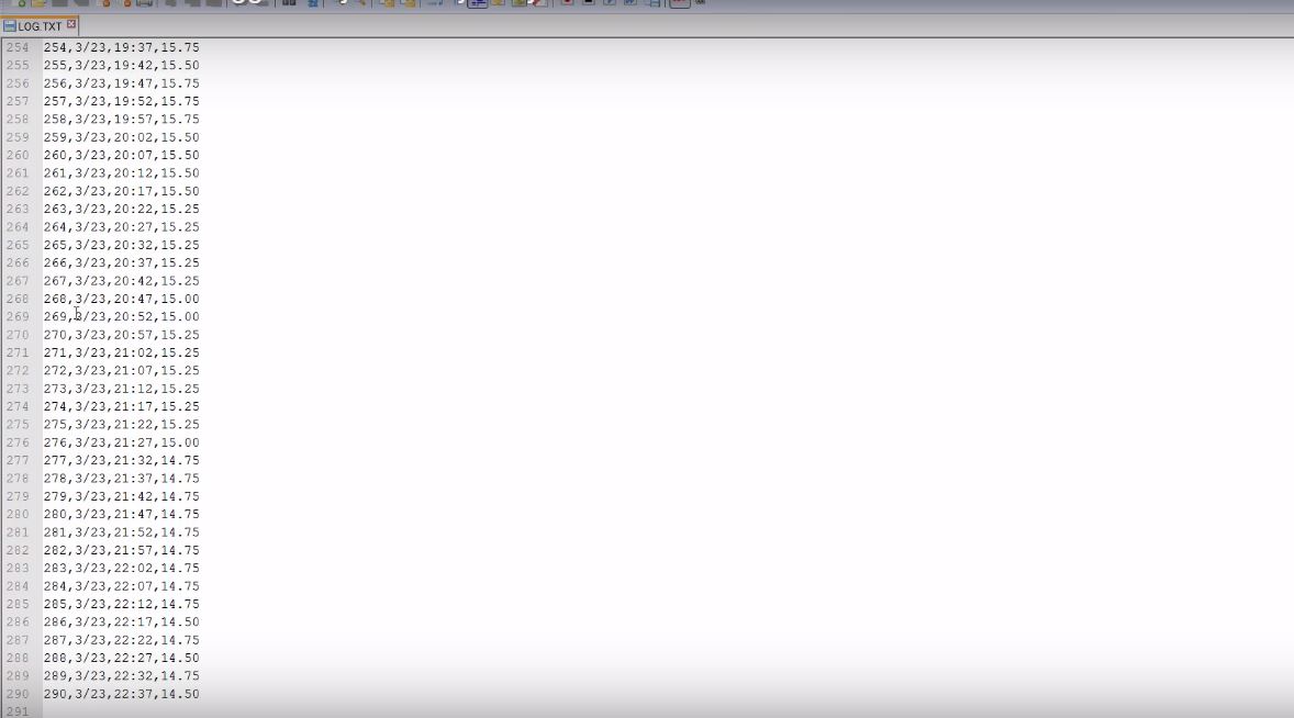
If you follow the steps carefully, wait for few minutes then remove your sd card. If you did everything correctly, you should see something like the image below on your computer screen when the SD card opens. The amount of data stored would depend on the amount of up-time the logger had before you removed the sd card. For example, for this project, we left the device running for a day, logging data every 5-minutes and at the end of the 24 hours, we had logged over 300 data(image below).
Data
Viewing Data in Excel
Excel makes it super easy to plot your data and do analysis.
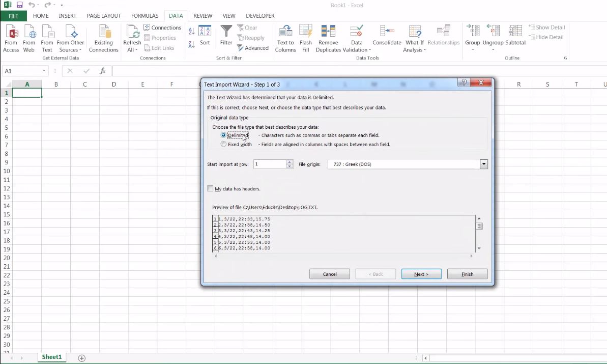
To generate a plot of the temperature against time for this project, open a new excel spread sheet, select data at the top, select from text, and navigate to the file on the SD card, and click OK, excel will prompt you to ask for details about the file, select delimited, then select by commas, after which excel will automatically import the data into your spread sheet.
Import files and set properties
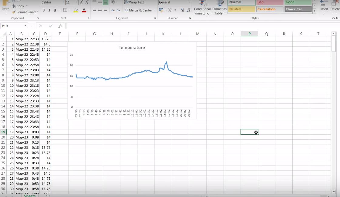
To Plot the data after the import, select the two columns, time and temperature (by holding the ctrl key) then go to insert tab and click on insert chart. you should see the chart pop up like the image below.
Graphed
That’s it for this tutorial guys, I hope you learn something from it. As usual, feel free to share your questions and contributions via the comment section.
The tutorial video for this tutorial is available on youtube here.