Many companies in the electronics manufacturing industry face the issue of excess inventory at some point, and with new technology constantly emerging this will remain the case.
Companies may think that selling excess is a difficult or time consuming process, but by outsourcing the problem to a professional excess inventory management company, it is actually very straightforward. As inventory ages, the value decreases so working with a reliable excess partner will help to realise the maximum value for your stock.
CCL provides electronics manufacturers and distributors with a one-stop solution to their excess component inventory.
100% focused on inventory management, CCL has evolved to assist thousands of electronics companies with managing their inventory, freeing up valuable warehouse space and improving cash flow.
CCL’s 20 years’ experience is gained by partnering with some of the best-known technology companies globally, and their team are ready to make an offer that works for you.
Send CCL your list of excess electronic components including:
• Manufacturer part number
• Manufacturer
• Date code
• Quantity
• Pictures and other information
Once CCL receive your list, their team will review it and make a competitive offer for your surplus stock.
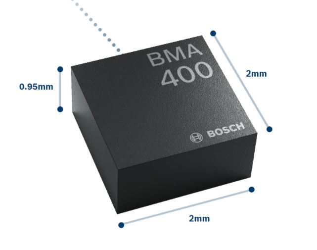
Accelerometers are used in almost all fields, and they have been growing in popularity in IoT and wearables. Nowadays, those devices require a of energy, and because of this, they need to be constantly charged or batteries need to be constantly changed which causes users to lose interest, or to be limited by this problem. Size might be a problem too because some MEMs (micromechanical systems) acceleration sensors are too big to be implemented in everyday portable objects. In June 2018, Bosch will unveil their BMA400, a sensor that extends battery life and has a huge range of capabilities in a small size.
BMA400 is capable of measuring tilt, orientation, tap/double tap, and step counting (with activity recognition) using a low- noise measurement of accelerations in three perpendicular axes. Additionally, the device only uses 10% of the energy current comparable devices use which makes it useful for applications where charging is impossible. For example, this device could be used for package tracking over long distances, saving power by putting itself on sleep mode until something happens (the package is mishandled) which could compromise the quality of the product inside the package.
Other applications include home automation (automatic air conditioning that considers status (open or closed) of windows and doors), security (burglar detection), and sports. The BMA400 includes an activity detection function that can differentiate between walking, running, and standing. All this could be applied into wearables, and because of its size it could be a game changer in hybrid smartwatches (traditional watch with added smarts in a discrete way).
BMA400 measure only 2 mm x 2 mm x 0.95 mm, and device data can be retrieved over longer intervals (FIFO buffer of 1kB). Other specifications include:
12-bit digital resolution
Output data rate (ODR) of 12.5 Hz to 800 Hz
Supply voltage of 1.71 V up to 3.6 V
Complete list of specifications can be found in the official website.
This improvements in an already widely used technology could result in advances in thousands of different devices, and in the implementation of this sensor in devices where it couldn’t be fitted before. Improving battery means improving product usability which results in happy users who can now use their device for longer periods of time. Also, makers and hobbyists could now apply this technology to new devices using the increased battery life as an advantage.
DuPont Advanced Materials (DuPont) in association with Taiwanese company Formosa Taffeta, has developed a powered smart clothing technology named Intexar™ Heat, for on-body flexible heating garments.
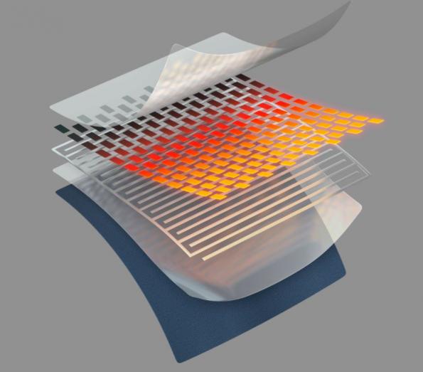
The new fabric is thin, lightweight, and durable. The Intexar™ Heat is an ideal solution for outdoor clothing and it is designed to be easily integrated into garments. This innovative technology consists of a thin layer of carbon resistors, interconnected by an underlying layer of silver electrodes printed on a stretchable thermoplastic polyurethane (TPU) laminate. The silver electrodes supply currents throughout the resistor grid to radiate a right amount of heat within garments. By default, the active layer is sandwiched between a plain or customized outer protective layer. This protective layer shields the heating element from exposure and the fabric making up the garment.
Intexar Heat powers smart clothing technology for on-body heating
Michael Burrows, the global business manager at DuPont Advanced Materials, described Intexar™ Heat as a revolutionary stretchable ink and film that when powered, creates a comfortable warmth. Formosa Taffeta Company will be the first textile manufacturer to apply Intexar™ Heat technology as part of its Permawarm® line. The new Permawarm® lineup will provide clothing with a complete garment heater system including the Intexar™ heater layer, connectors, and control software.
James Lee, president of FTC, said,
With Permawarm™, clothing brands can focus on garment design and brand engagement. We are taking the guesswork out of bringing their customers safe and comfortable heated garments.
Intexar™ materials can also be very useful in biometric monitoring in smart clothing. Pulse rate, respiratory rate, muscle activity and form awareness are all measurable using sensors and conductive pathways built from Intexar™ which makes it a complete smart garment solution.
To cope with the coming era of functional thermal insulation this is a huge step forward for heat-insulation fabrics. It is a new high-tech lightweight material ideal for thermal insulation in the winter.
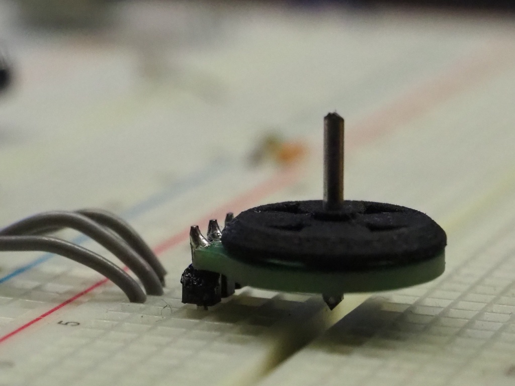
by Carl Bugeja @ hackaday.io designed a brushless motor using a 3D printer and a 4-layer PCB. He writes:
The PCB motor is my solution for trying to design a smaller, cheaper and easier to assemble brushless motor.
The motor’s stator is a 6 spiral PCB coil in a star configuration. Although it has less torque compared to an iron core stator, it still suitable for high-speed applications.
The current prototype has a 3d printed rotor with a 16mm diameter.
PCB Motor – A smaller and cheaper brushless motor – [Link]
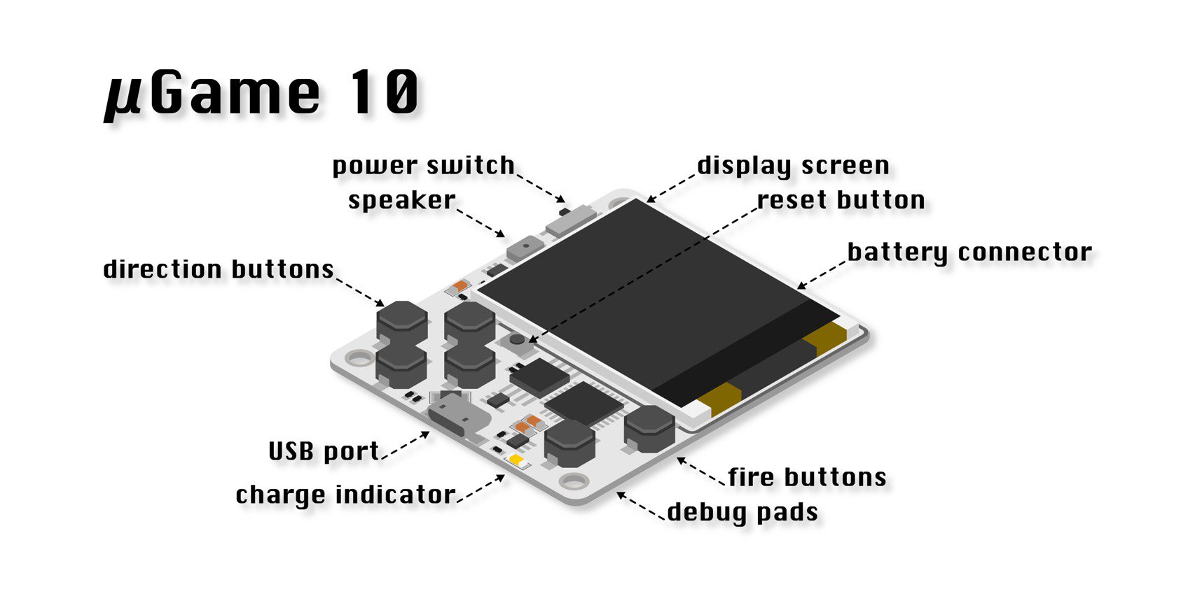
If you want to have fun by playing games and also learn about Python Programming language, the µGame console kit might be your best bet.
There are some game consoles out there in the market, like Pokitto, Okitto, and others. These game consoles give the ability to play several games and even build your own by programming it yourself. One of the significant challenges with these game consoles is the process it takes to develop and deploy a game, one has to go through the whole process of installing the compiler and IDE, compile the program with the hope of getting it to build successfully. This entire process could be a daunting task for a beginner, but the µGame 10 console kit from Deshipu seems to beg the difference.
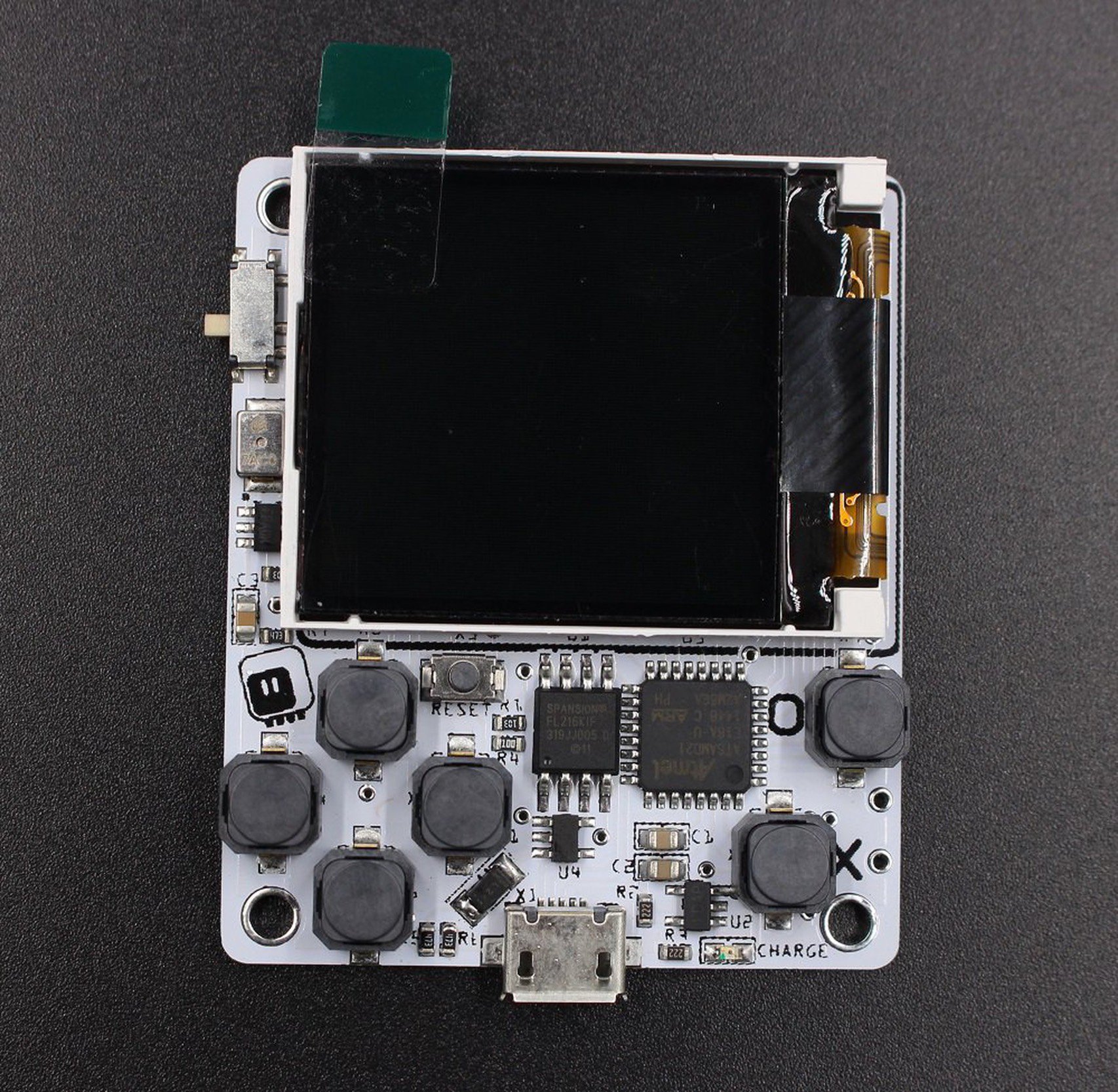
µGame is a game console kit from Deshipu that allows you to play games and write them using the Python programming language. Unlike other gaming kits that require the code to be compiled first before uploading to the device, µGame doesn’t require compilation. The program can be uploaded directly to the console, and it will start playing it. It’s based on Adafruit’s CircuitPython – a version of Python that runs a python code without an operating system. CircuitPython is Adafruit’s branch of MicroPython designed to simplify experimentation and education on low-cost microcontrollers.
At a footprint of 1.44 inches, µGame takes the form of a small handheld game console with a 128×128 OLED screen. This portable game system can be attached to a computer via its built-in micro USB port where it will show as a USB drive, and doesn’t require any driver for that. The built game source code can be copied directly to the drive where it can now be executed and even modified. The game console can be removed from the computer and the game copied inside will be available for execution.
The console kit is supplied only with board, the display, and a battery charging unit. The user is expected to attach the OLED display, and a battery to begin using it. Unlike other gaming consoles like the Pokitto that comes with an enclosure, µGame doesn’t come with an enclosure but you can 3D print your custom case for it. The system provides an easy way to edit code if desired from the µGame, and the console will automatically restart if changes in the code are detected, or you run your new program.
Some Specifications of the µGame DIY games console include:
Atmel SAMD21 ARM Cortex M0 at 48MHz
32kB RAM
2MB flash storage space for the files,
a 1.44″ 128×128 TFT 16-bit color display,
4mm mono speaker
Six buttons
400mA battery charging circuit
The game console kit is available and can be purchased on Tindie for $25. Although the game console kit comes with a battery charging circuit, it doesn’t include any battery. Aside from the lack of battery, the game console comes with few games and is more tailored for those that want to write their games.
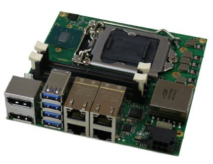
USA based ADL Embedded Solutions has introduced a new rugged, Nano-ITX form factor ADL120S single board computer (SBC). It is mainly produced for IoT, networking, and cyber-security applications. The highlighted feature of this SBC is its wide variety of PCIe expansion slots. The SBC includes 8x stackable PCIe interfaces, as well as optional custom expansion board services. Also, you get dual M/2 Key-B 2280 interfaces that support PCIe/SATA with USB 3.0. Networking is taken care with 4x Gigabit Ethernet ports (1x with PXE boot and WoL).
ADL120S Single Board Computer by ADL Embedded Solutions
The ADL120S runs Linux or Windows OS on dual- or quad-core Intel 6th Gen (“Skylake“) processor and Celeron CPUs that support an LGA1151 socket. There’s an Intel Q170 chipset on ADL120S instead of a Q170HDS. The supported SKUs include the quad-core 2.4GHz Core i7-6700TE, the dual-core 2.7GHz i3-6100TE, and 2.3GHz Celeron G3900TE.
The board has a compact dimension of 120 x 120mm in a Nano-ITX form factor but has a high vertical profile with 4x USB 3.0 ports piled on a single column. This high-rise board also includes 4x GbE ports, one of which has WoL and PXE Boot, and a pair of DisplayPort 1.2 ports with 4096 x 2304 resolution at 60Hz refresh rate.
The ADL120S comes with up to 32GB DDR4 RAM and offers a wide-range 20-30VDC (optional 12-24V or 20-36V) input and RTC (Real time clock) with battery. The boards with -20 to 70°C or -40 to 85°C temperature range of usability are available.
The SBC is also praised for its high MTBF, long-life availability, hardware and firmware revision control, obsolescence management, and technical, engineering and design support, on their website’s product page.
No pricing or availability information was provided for the ADL120S.
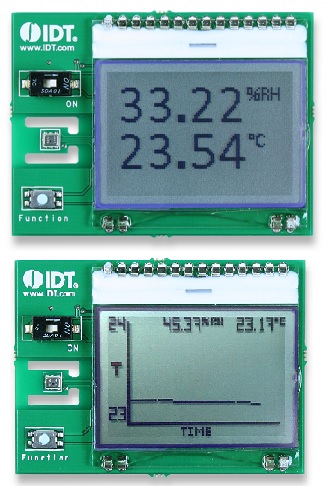
California based company, Integrated Device Technology (IDT) has recently announced their new HS300x family of MEMS high-performance relative humidity (RH) and temperature sensors of dimension 3.0 × 2.41 × 0.8 mm DFN-style 6-pin LGA. Currently, there are four devices in this family—the HS3001, HS3002, HS3003, and HS3004. They are all the same from the view of functionality but differ slightly in terms of the accuracy of their relative humidity and temperature measurements.
Development board for ITD MEMs sensors
The highlighted feature of this new lineup is that they do not require any user calibration. HS300x family of ICs has calibration and compensation logic integrated into the devices. These ICs output their fully corrected data using standard I2C protocols making the measured data from the sensors is rather easy.
As a side note, Relative humidity (RH) is the ratio of the partial pressure of water vapor to the equilibrium vapor pressure of water at a given temperature. As the entire output consists of only four bytes of data, calculating the corresponding relative humidity in percent and temperature in degrees Celsius is very easy.
Although the HS300x sensors operate as slave devices on the I2C bus (supporting clock frequencies from 100 kHz to 400 kHz), only one HS300x IC can be connected directly to a single I2C bus. To connect multiple sensors to a single I2C bus, an I2C multiplexer/switch has to be used. It would have been easier if IDT had dedicated the unused pin as an optional I2C address input bit, which would allow two HS300x devices to be connected to a single I2C bus.
If you’re interested in testing these ICs prior to incorporating them into a design, SDAH01 or SDAH02 evaluation kit can come handy. Although both kits utilize the HS3001 sensor, the SDAH01 kit outputs the measured data to a PC while the SDAH02 displays the data on an LCD screen.
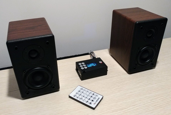
Continuing the success of NanoSound DAC, Nanomesher @ kickstarter.com introduces the Digital version – NanoSound Digital and ready-to-run Player.
NanoSound digital is all-in-one audio add-on for Raspberry Pi NanoSound Digital provides essential functionalities including high-quality S/PDIF audio output, Media Control Buttons, Display, Remote control and Pi Power Switch, all in one package which fits neatly on top of your Raspberry Pi. NanoSound Digital is the S/PDIF digital output version of NanoSound DAC. It is compatible with HiFiBerry Digi audio driver.
Specifications
Wifi & Wired Ethernet Network
Play everything – MP3, FLAC, WAV, AAC, ALAC, DSD and many more
Spotify, Airplay, DLNA, Youtube & Free Web Radio
Play from Internal Storage, NAS and USB Flash
Control via Volumio App or Infrared Remote Control
1.3″ OLED display with multi-language support
AUX and 3.5mm output
Texas Instruments PCM5122 DAC. 192kHz Sampling Rate / 24bit Resolution Burr-Brown DAC for best sound quality
Texas Instruments TPS7A4700 Ultra Low Noise Voltage Regulator
Output Power: 24mW @20Ω, 22mw @32Ω
Signal-To-Noise Ratio (SNR): 100db @20mW
Total Harmonic Distortion + Noise (THD+N): 0.01% @25mW
We published a new tutorial in partnership with Nik Koumaris from educ8s.tv.
Often, we have the need for a way to store data in our projects, and most of the time, the EEPROM has not enough storage and the storage size is limited. It also has issues with the format and nature of data it can hold, all this and more makes it probably not the best for storing data like text, CSV, audio, video or image files. To get around this we could use an SD card to store the data, and remove the card when we need to view on some other platform etc. That is why today’s project is focusing on how to interface an SD card module with an Arduino.
Interfacing the Arduino with the Micro SD card Module – [Link]
Often times, we have the need for a way to store data in our projects, and most of the time, the EEPROM which comes readily to mind has a limited storage capacity, and issues with the format and nature of data it can hold. All this and more makes it probably not the best for storing data like text, CSV, audio, video or image files. To get around this we could use an SD card to store the data, and remove the card when we need to view on some other platform etc. That is why today’s project is focusing on how to interface an SD card module with an Arduino.
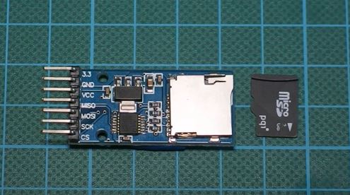
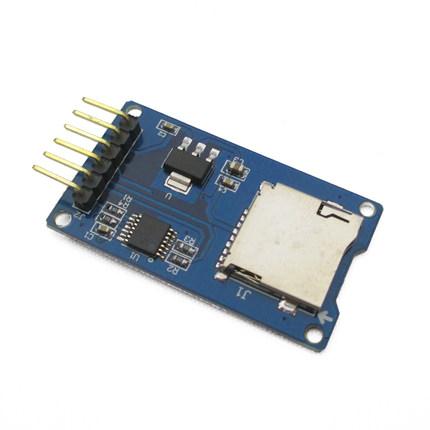
The Arduino Micro SD card Module is an SPI Communication based device. It is compatible with the TF SD cards used in mobile phones and can be used to provide some sort of external storage for micro controller and microprocessor based projects, to store different kind of data types from images to videos. SD cards generally are 3.3v logic level based devices, but with the aid of the Micro SD card module, the signals are converted to 5v via a logic level converter implemented on the SD card Module.
Required Components
To achieve the goals of this tutorial i.e. learn to interface the Arduino with the Micro SD card module, we will need the following components;
As usual, the exact components used for this tutorial can be gotten by clicking on the components above.
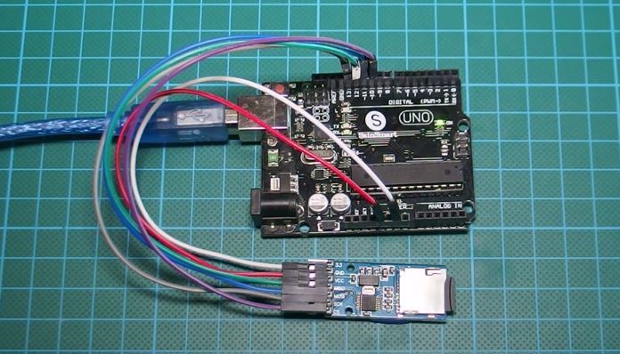
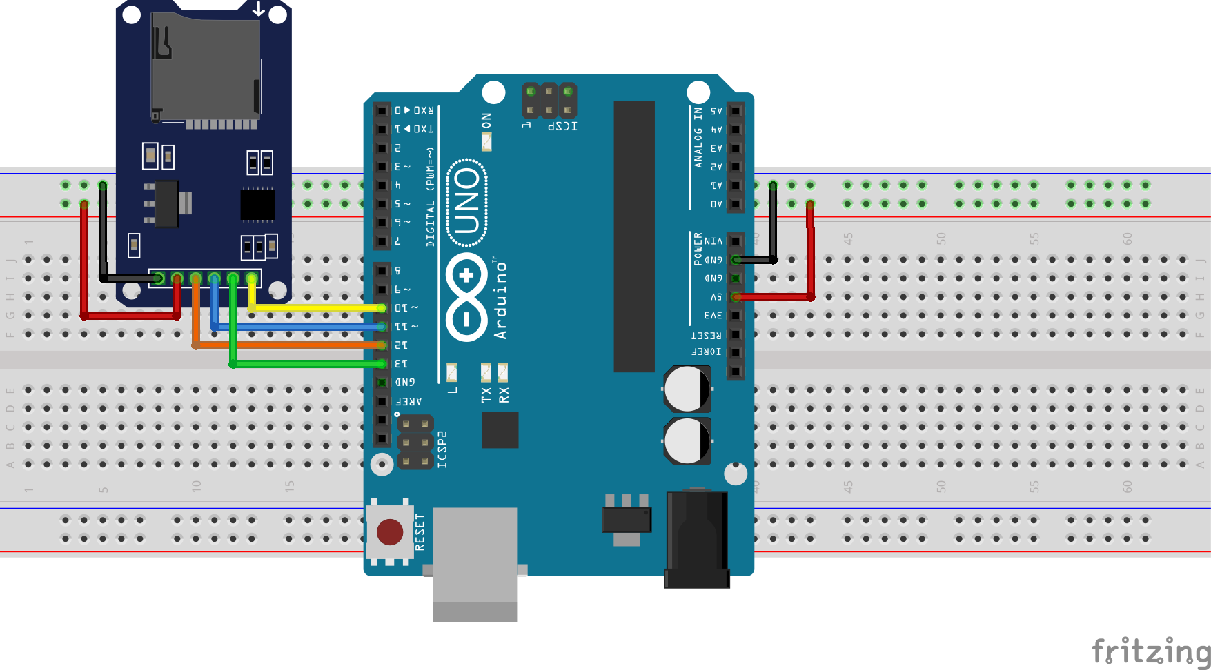
Schematics
Connect all the components as shown in the schematics below.
Schematics
The SD card module as earlier stated, communicates with the arduino over the SPI (serial Peripheral interface) communication protocol and it is connected to the arduino hardware SPI pins. The SPI pins on an Arduino differs from one arduino to the other, but on the UNO which was used for this project, it is found between pin 10 to 12. To further highlight the connection made in the fritzing schematics above, below is a pin map of the connection between the SD card and the Arduino Uno;
The code for this tutorial will be based on the standard SD.h arduino library. It is one of the libraries that comes with the the installation of the IDE. The aim of this code is to basically show us the functions that can be performed with the SD card module, including read, write, etc.
As usual, I will do a breakdown of the code here, and will then drop the full code at the end. The code will also be attached in a zip file at the end of this post.
So to jump right in, the first thing we do in the code is include the libraries that we will be using as shown below. We will basically be using the Arduino SD library and the SPI.h library which allows us to easily use the Arduino hardware SPI.
    /////////////////////////////////////////////////////////////////
   //              Arduino SD Card Tutorial     v1.00             //
  //       Get the latest version of the code here:              //
 //         http://educ8s.tv/arduino-sd-card-tutorial           //
/////////////////////////////////////////////////////////////////
#include <SD.h>
#include <SPI.h>
After the libraries have been declared, the next thing we do is declare the pin to which the CS pin of the SD card module is connected to the arduino. The CS pin is the only one that is not really fixed as any of the Arduino digital pin. We didn’t need to declare the other SPI pins since we are connected to the generic SPI pins and we have the SPI library included. After declaring the pin, we then create an object file, which will be used later on to store data on the SD card.
int CS_PIN = 10;

File file;
Next we move to the setup() function of the arduino code. The first thing we do is start the serial communication at 9600 baud rate. We then initialize the SD card with the next line of code, after which we create a file named test.txt and then write to it using the writeToFile() function. After writing to the file, it is closed. This section of the void setup() function was just used to demonstrate how easy it is to write text/data to a file.
With that done we then move to the second part of the void setup where we will attempt to read the data stored in a file and display it on the serial monitor.
The first thing we do is open the file, then we use the next line of code to print each line of the text found in the file using the readline() function. After the data has been read, we close the file.
It should be noted that the prefs.txt file was already created on the SD card initially or else we would have an error when we tried to open it.
Since this was just a demo sketch to show how to read and write files, there was no point to run the code multiple times so they were all placed in the void setup() function which runs just once, instead of putting it in a void loop which runs for as long as you have power. Thus the void loop was included but with nothing inside, as you may have noticed, your arduino code will not compile without the void loop() function included. After the loop() function,are the code for the functions that were used under the void setup(), to read or write to the SD card.
void loop()
{
}
The full code is written below, and also attached in a zip file at the end of the post.
/////////////////////////////////////////////////////////////////
// Arduino SD Card Tutorial v1.00 //
// Get the latest version of the code here: //
// http://educ8s.tv/arduino-sd-card-tutorial //
/////////////////////////////////////////////////////////////////
#include <SD.h>
#include <SPI.h>
int CS_PIN = 10;
File file;
void setup()
{

  Serial.begin(9600);

  initializeSD();
  createFile("test.txt");
  writeToFile("This is sample text!");
  closeFile();
 openFile("prefs.txt");
  Serial.println(readLine());
  Serial.println(readLine());
  closeFile();
}
void loop()
{
}
void initializeSD()
{
Serial.println("Initializing SD card...");
pinMode(CS_PIN, OUTPUT);
if (SD.begin())
{
Serial.println("SD card is ready to use.");
} else
{
Serial.println("SD card initialization failed");
return;
}
}
int createFile(char filename[])
{
file = SD.open(filename, FILE_WRITE);
if (file)
{
Serial.println("File created successfully.");
return 1;
} else
{
Serial.println("Error while creating file.");
return 0;
}
}
int writeToFile(char text[])
{
if (file)
{
file.println(text);
Serial.println("Writing to file: ");
Serial.println(text);
return 1;
} else
{
Serial.println("Couldn't write to file");
return 0;
}
}
void closeFile()
{
if (file)
{
file.close();
Serial.println("File closed");
}
}
int openFile(char filename[])
{
file = SD.open(filename);
if (file)
{
Serial.println("File opened with success!");
return 1;
} else
{
Serial.println("Error opening file...");
return 0;
}
}
String readLine()
{
String received = "";
char ch;
while (file.available())
{
ch = file.read();
if (ch == '\n')
{
return String(received);
}
else
{
received += ch;
}
}
return "";
}
Demo
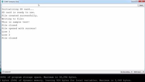
Copy the code above and paste it into the Arduino IDE, Upload it to your board and you should see something like what is displayed below on your serial monitor.
Serial Monitor Display After Uploading the code
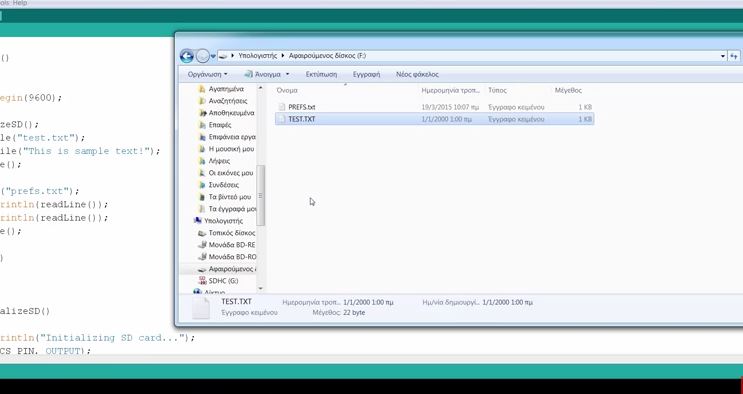
When the SD card is removed and inserted into a computer, the following is seen.
The content of the SD card became two.
That’s it for this tutorial guys, let me know if you have any questions via the comment box.
A video of this tutorial can be found on the educ8s.tv channel here.