First Orange Pi SBC Powered By Rockchip’s Hexacore SoC Can Run Android 6.0 And Debian 9

ARM hacker board vendors and commercial x86-centric board vendors are following Firefly’s lead in experimenting with Rockchip’s ARM-based SoCs. These new single-board computers (SBC) offer x86-type features like HDMI 2.0, mSATA, and mini-PCIe. They also come with powerful and more energy-efficient ARM cores. Now Shenzhen Xunlong has launched its first Rockchip based Orange Pi single-board computer, Orange Pi RK3399, at 109 USD.

Orange Pi RK3999 Powered By Rockchip SoC

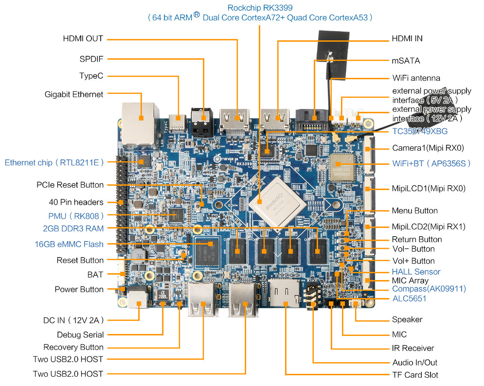
The Rockchip RK3399 features two Cortex-A72 cores that are clocked up to 2.0GHz, as well as four Cortex-A53 cores typically clocked at up to 1.42GHz. There’s also a high-performing ARM Mali-T864 GPU. There are 2GB DDR3 RAM, 16GB eMMC flash and can be expanded with an inbuilt MicroSD slot. Mandatory I/O ports as USB 3.0 Type-C port, 4x USB 2.0 host ports. DisplayPort 1.2 with audio for up to 4K at 60Hz. There are Other RK3399 based SBCs as Firefly’s Firefly-RK3399 and similarly open source Rockchip RK3399 Sapphire.

Like most of these boards, the Orange Pi RK3399 is a high-end board with various ports and interfaces. The Orange Pi RK3399 is the only one of these SBCs with mSATA, and you can have dual mSATA drives if you dedicate the mini-PCIe slot to mSATA instead of LTE. Orange Pi RK3399 stands out with its numerous sensor assembly, which includes a G-Sensor, Gyro, Compass, HALL sensor, and ambient light sensor.

Orange Pi RK3999 front details

The Orange Pi RK3399 offers almost the same as Firefly-RK3399, with GbE, WiFi-AC, Bluetooth 4.1, and a large-scale collection of multimedia features. There’s a 40- instead of 42-pin expansion interface. Just like Firefly boards, there is no support for Raspberry Pi compatibility. The board also lacks the Firefly’s RTC, and at 129 x 99mm, which is heavier and just slightly larger than the Firefly-RK3399.

One of the best advantages of the Firefly board is software support. Firefly offers Ubuntu 16.04 while the Orange Pi only has Debian 9 along with Android 6.0. More importantly, since this is Shenzhen Xunlong’s first Rockchip board, software support is likely to procrastinate. Hopes are high on this being an open hardware board like the other Orange Pi models.

Update 16/01/2019

Shenzhen Xunlong has now introduced a 4GB RAM version of the board for $99.96, with the 2GB version now selling for $89.38. Both boards can be purchased on Aliexpress. Apart from the RAM capacity, Orange Pi RK3399 “4G” specifications have not been changed.

Regarding software you’ll find Android and Ubuntu/Debian desktop/server images that have last been updated in February / March of 2018 in the download page, as well as the Android SDK and Linux source code.

Understanding Flash Memory And How It Works

Flash memory is one of the most widely used types of non-volatile memory. NAND Flash is designed for modern file storage which replaced old disk drives. This article provides a brief understanding of how NAND Flash technology works.

The basic storage component used in Flash memory is a modified transistor. In a standard transistor, the flow of current through a channel between two contacts is turned on by a voltage applied to the gate. The channels are separated by an insulating layer of Oxide. In a Flash storage cell, there is an extra electrically isolated gate called “floating gate”. It is added to the control gate and the channel of the modified transistor.

Different Flash Storages
Different Flash Memory Devices

High voltage is applied to the control gate of The Flash cell to program it. This pushes electrons to pass through the oxide layer to the floating gate (a process known as tunneling). The presence of these trapped electrons on the floating gate changes the required voltage to turn on the transistor. Thus, a transistor with no charge on the floating gate can easily turn on at a certain voltage, representing a 1, while a programmed cell will not turn on, representing a 0.

This kind of memory is non-volatile because the floating gate is surrounded by dielectric layers, it traps the electric charge even when the power is removed. Erasing a cell reverses this process by introducing a large negative voltage to the control gate to force the electrons to tunnel out of the floating gate.

NANAD Flash storage internal
NAND Flash Memory storage internal

A number of cells, typically 32 to 128, are connected in a string. Strings are organized in blocks. To program cells in a block, the data is put on the bit lines and a high voltage is applied. Because programming can only change a cell from a 1 to a 0, any cells where the new data is a 1, will be left in their current state. Therefore, all the cells must be erased before writing. This process ensures that any cells that will not be programmed already contain a 1.

As explained above, each cell can store a single binary value, 0 or 1. It is also possible to inject varying amounts of charge onto the floating gate so that the cell can express multiple values. A multi-level cell (MLC) can store four different levels to represent two bits. However, the performance is reduced because of the complexity of accurate voltage controls. For the same reason, MLC Flash memory is more inclined to errors.

Although flash memory has a limited number of write-erase cycles, the high voltages cause a small amount of damage to the cells which makes them harder to read-write over time. The main drawback of using a flash memory is that it has a lifetime of about 100,000 cycles or fewer for MLC Flash.

Tiny FPGA BX – A Tiny, Open Source FPGA development board for Makers

The TinyFPGA boards from Luke Valenty (TinyFPGA) are a series of low-cost, open-source FPGA development boards. These boards offer an inexpensive way to get an introduction to the world of FPGAs.

If you have ever considered working with an FPGA before, you will know how difficult they could be especially for those new to the game. TinyFPGA boards are an excellent way to kickstart development with them. They are breadboard friendly, and one can put up a simple circuit around them before adding things like sensors or actuators.

The TinyFPGA boards are currently made up of about three series – The TinyFPGA A1 that offers an X02-256 containing 256 logic cells; the A2 sports with an X02-1200 of about 1200 logic cells, and lastly the B2 boats an ICE40LP8K with 7680 logic cells. They are low cost in nature, costing about $12,00, $18,00 and $38.00 respectively. The latest upcoming release to the TinyFPGA board family is the TinyFPGA BX.

Like the other Tiny FPGA Boards, the Tiny FPGA BX boards is quite flexible and powerful. The BX boards are intended for the maker’s community. The BX module allows one to design and implement a digital logic circuit in a tiny form-factor, and it’s perfect for building with breadboards or custom PCBs.

The TinyFPGA BX shares close similarities with the TinyFPGA B2 and are both based on the Lattice ICE40LP8K FPGA Chip with about 7680 logic cells. The BX board will offer an incredible power to project development and allows to achieve things not usually expected on traditional microcontroller boards at a fraction of the cost.

According to Luke, the TinyFPGA BX prototype boards are currently being manufactured. The PCBs have been fabricated and are now waiting for assembly.

The BX measure at 0.7 by 1.4 inches and comes with a built-in USB interface, and preloaded with a USB Bootloader. It is expected to have 8Mbit of SPI Flash with only 5Mbit available for user applications.

The following are some of the available board specifications:

  • ICE40LP8K FPGA
    • 7,680 4-input look-up-tables
    • 128 KBit block RAM
    • Phase Locked Loop
    • 41 IO pins
  • Small, breadboard friendly form-factor
    • 0.7 by 1.4 inches
  • Built-in USB interface with open source USB bootloader
  • 8MBit of SPI Flash with 5MBit available for user applications
  • Integrated 3.3v and 1.2v regulators
    • 3.3v LDO regulator can supply up to 300ma of current to support external peripherals
  • Ultra-Low-Power 16MHz MEMs Oscillator
    • 1.3ma active power
    • 50ppm stability

These TinyFPGA boards offer an inexpensive way for hackers and makers to get an introduction to the world of FPGAs. And, with their small size, these boards can provide an easy way to add some programmable logic to a small project.

FPGA gives us the power to add real deal hardware functionality to our project, unlike with Microcontroller, where those features can only be added to a bit of software banging. The TinyFPGA Bx boards are still not fully launched yet, so now price point is currently available but is expected to share similar costing with the TinyFPGA B2 at $38.00.

More information about the project launch can be found on the crowdsupply page and also on the hackaday board page announcement. If you are interested in getting introduced to the world of FPGA, this guide from Luke is an excellent way to kickstart your adventure.

Revolutionizing Electric Field Measuring Techniques

Nowadays, electrical fields are being used not only in electrical engineering, but also for industrial, weather forecasting, safety, and medical applications. As a result, the need for a precise electric field strength measurement device has become increasingly high, and many investigations have devoted their resources to creating such device. TU Wien has developed a small electric field sensor that is much simpler, and most importantly, it is less prone to distortion.

There are a lot of measurement systems in the market. However, most of them are big, depend on complex surrounding calibration procedures, or the device is grounded to provide a reference measurement. All these factors cause distortion that affects the measurement. Additionally, dielectric devices develop surfaces charges that also lead to distortion, and conductive metallic components can have the same effect.

The sensor made by TU Wien is made from silicon forming a small, grid shaped structure fixed onto a small spring, so that when the silicon is exposed to an electrical field a force is exerted on the silicon crystals causing the spring to compress or extend. Another grid was added to make these slight changes visible. The silicon grid is lined up, so when movement occurs, light can pass through which is then measured and used to calculate the electrical field. It can only measure strength not direction, and it can be used for fields of up to 1 k Hz.  The silicon structures are just a few micrometers in diameter making it much smaller than conventional sensors.

This method of measurement is new, Andreas Kainzs from the Institute of Sensor and Actuator Systems says that in the future they would be able to achieve even better results as the measuring technique matures. The sensor is a micromechanical systems (MEMs) that has the potential for replacing the measuring techniques used nowadays. This device is not only less prone to distortion, but also portable, easy to transport and capable of fitting into wearables. The prototype has can measure weak fields of less than 200 volts per meter. This means that in terms of measuring capabilities, this sensor can easily compete with those already in the market. The sensor is not currently being sold, and TU Wien plans on keep improving the device.

[Source]

Low Cost/Voltage 3W Class-D Stereo Audio Amplifier for Portable Gadgets

This low cost low voltage 3W class-D stereo amplifier is based on PAM8403 IC, The PAM8403 is a 3W, class-D audio amplifier. It offers low THD+N, allowing it to achieve high-quality sound reproduction. The new filter-less architecture allows the device to drive the speaker directly, requiring no low-pass output filters, thus saving system cost and PCB area. With the same numbers of external components, the efficiency of the PAM8403 is much better than that of Class-AB cousins. It can extend the battery life, which makes it well-suited for portable applications. Trimmer Potentiometer helps to adjust the volume control, CN1 provided to feed the audio signal, CN2 power supply, Mute and shutdown in, LS1 and LS2 to connect the speaker. Shutdown and Mute pin required high level signal input, and can be connect to VDD power pins for normal operation, can be connect to GND for shutdown or mute the audio. The amplifier works well with standard audio signal input.

Low Cost/Voltage 3W Class-D Stereo Audio Amplifier for Portable Gadgets – [Link]

Low Cost/Voltage 3W Class-D Stereo Audio Amplifier for Portable Gadgets

This low cost low voltage 3W class-D stereo amplifier is based on PAM8403 IC, The PAM8403 is a 3W, class-D audio amplifier. It offers low THD+N, allowing it to achieve high-quality sound reproduction. The new filter-less architecture allows the device to drive the speaker directly, requiring no low-pass output filters, thus saving system cost and PCB area. With the same numbers of external components, the efficiency of the PAM8403 is much better than that of Class-AB cousins. It can extend the battery life, which makes it well-suited for portable applications. Trimmer Potentiometer helps to adjust the volume control, CN1 provided to feed the audio signal, CN2 power supply, Mute and shutdown in, LS1 and LS2 to connect the speaker. Shutdown and Mute pin required high level signal input, and can be connect to VDD power pins for normal operation, can be connect to GND for shutdown or mute the audio. The amplifier works well with standard audio signal input.

Specifications

  • Supply 3.6V 5V DC
  • 3W Output at 10% THD with a 4Ω Load and 5V Power Supply
  • Filter less, Low Quiescent Current and Low EMI
  • On Board Trimmer potentiometer to Adjust The Volume
  • Low THD+N
  • Very Small Size Board
  • Superior Low Noise
  • Efficiency up to 90%
  • Short Circuit Protection
  • Thermal Shutdown

Schematic

Parts List

Connections

Photos

Video

ESP32 E-Paper Thermometer with a DS18B20 Sensor

Our friends on educ8s.tv published a new video. Check it out.

In this ESP32 project video, we are going to use an E-Paper display and a DS18B20 temperature sensor to build a low-power thermometer. We are going to use the Arduino IDE to program to ESP32 board. ! It is a very easy project to build. It won’t take us more than 5 minutes so let’s get started!

ESP32 E-Paper Thermometer with a DS18B20 Sensor – [Link]

Adafruit Feather 328P – Arduino Uno on the Feather Family

Adafruit Feather 328P is the latest addition to the ever-expanding feather family boards manufactured by Adafruit. The Adafruit Feather development boards are a set of development boards made by Adafruit that can either be standalone, stackable or both. The feather boards all includes a LiPo battery connector, which will allow projects to easily be powered by LiPo batteries for on the go use.

Adafruit Feather 328P

The Adafruit Feather 328P is based on the popular Atmega 328P, the same processor that powers most Arduino maker boards especially the legendary Arduino Uno. With the Feather 328P, you can bring classic Arduino Uno code and even libraries to the Feather form factor. Measured at about 51mm x 23mm x 8mm (without the headers soldered in) and it weighs just 4.8g.

The Feather 328P is lightweight and a small form factor development board. At the heart of the Feather 328P is an Atmel ATmega 328P running a 3.3V and 8MHz. At 8MHz, the feather 328P can’t fully compete with the Arduino Uno which runs at 16MHz but is fair enough. The Feather 328P includes a 32KB of flash memory (storage memory), 2KB of RAM, and it uses the SiLabs CP2104 to give it a USB-to-Serial program which also provides users with some integrated debugging capabilities.

feather on a breadboard

The Feather 328P boards come without any headers soldered, so you have to solder yourself to start using it for prototyping. Unlike the Arduino Uno and some other Arduino board which are not fully breadboarding compatible, the Feather 328P fits perfectly into a breadboard and will be great for quick prototyping without the need for jumper cables.

Like other Feather development boards, the Feather 328P also includes a LiPo battery connector for any 3.7V Lithium Polymer batteries with a built-in battery charging. It will charge straight from the micro USB port, and you don’t necessarily need a battery to make it work, it will run just fine straight from the micro USB connector. The Feather will automatically switch over to USB power when it’s available making sure your project never goes offline as far you still got some juice in the battery though. You can also measure the battery voltage through one of the analog pins, the analog pin must not be connected to anything for this to work.

The following are some of the specifications of the Feather 328P:

  • Size  – 2.0″ x 0.9″ x 0.28″ (51mm x 23mm x 8mm)
  • Weight – 4.8 grams
  • Processor – ATmega328p @ 8MHz with 3.3V logic/power
  • Power –
    • 3.3V regulator with 500mA peak current output
    • Built-in 100mA lipoly charger with charging status indicator LED
  • USB serial converter (CP2104) for USB bootloading and serial port debugging
  • GPIO –
    • 19 GPIO pins + 2 analog-in-only pins
    • 6x PWM pins
  • Connectivity –
    • Hardware I2C, SPI.
    • For UART devices, should use SoftwareSerial
  • Others –
    • 8 x analog inputs (two are shared with I2C)
    • Pin #13 red LED for general purpose blinking
    • Two LEDs for serial data RX & TX
    • Power/enable pin
    • 4 mounting holes
    • Reset button

The Feather 328P comes with an extra prototyping area to add some couple of components without using a breadboard. The Feather 328P is available for purchase and priced at $12.50, you can buy now online at Adafruit Store. To find out about the other feather boards, check them out here.

Infrared repeater using AVR mcu

Madis Kaal @ nomad.ee designed a infrared repeater based on ATMEL AVR + TSOP1738 infrared receiver. He writes:

I built this MCU based infrared repeater to allow me to control my A/V equipment that is behind a wall. The system is very simple.

Power is supplied to CON1 from a cheap Alcatel phone charger that outputs stabilized 12V, passes through reverse voltage protection diode to IC1 that outputs 5V VCC. Atmel AVR microcontroller runs from 4MHz ceramic resonator Y1, C3+R1 form a reset circuit. Infrared detector (TSOP1738 in my case) is connected to INT0 input, C1+R2 are for detector power filtering.

Infrared repeater using AVR mcu – [Link]

SODAQ ONE board – GPS + LoRa + Solar charger

This is the third generation of our succesful SODAQ ONE board. It is equipped with a solar charge controller and runs on a LiPo or a permanent battery. It has the Ublox Eva 8M GPS module which is not only miniature but with it’s assisted GPS feature it can get a fix within seconds. We’ve now added an extremely low power Accelerometer/Magnetometer. This gives the board a nifty feature where it can stay in (deep) sleep mode until it moves. An essential feature for developing low power devices.

Let’s imagine you want to develop a bicycle tracker using the SODAQ ONE. You would like to track the position of the bike, but only when it has moved. This is possible if you keep the device in deep sleep until it detects motion. If the motion continues for a while, the bicycle may have changed position so only then the GPS will switch on to get a new reading and send this location over the LoRa network. Efficient right? This system will allow you make most efficient use of your battery capacity by only using the GPS when really needed, essentially increasing the battery life of your system.

SODAQ ONE board – GPS + Solar charger board – [Link]

TOP PCB Companies