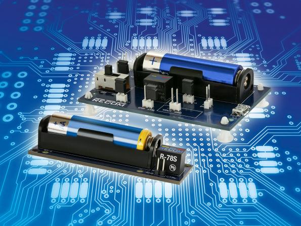
Recom’s first evaluation board allows engineers to effortlessly test the functionality of the R-78S switching regulator, which boosts a AA battery or external supply voltage to 3.3V for low power IoT applications. By Julien Happich @ eenewseurope.com:
The R-78S Evaluation Board demonstrates the performance of the R-78S which boosts single-cell AA battery voltage of 1.5V up to a stable 3.3V. This guarantees much higher energy capacities and reduces maintenance costs compared to button or coin cell batteries. This will effectively extend the operation lifetime of an application since the boost converter continues to operate at input voltages as low as 0.65V.
R-78S switching regulator boosts a AA battery to 3.3V – [Link]
Voice Assistants are becoming more widely accepted, devices like Amazon Echo, Sonos On, and Google Home devices are seeing the larger market share. The mounting interest in voice assistants and voice-activated platforms is leading to new ways of communicating, and in theory, creating additional channels to drive revenue.
It’s estimated that 30% of searches will be done without a screen in the next years, that there will be 21.4 million smart speakers in the US by 2020, and 2019 could put the voice recognition market to a $601 million industry. Amazon is paving the way for the possibility of these predictions with their goal of “Alexa on all Every Devices”, and the launch of the Amazon Alexa Voice development kit that will allow manufacturers easily integrate Alexa into their products. The voice-based platform could be the next stealth thing, after all, it’s easier to voice out your thoughts than type them out.
Espressif-Audio-Mic-HDK
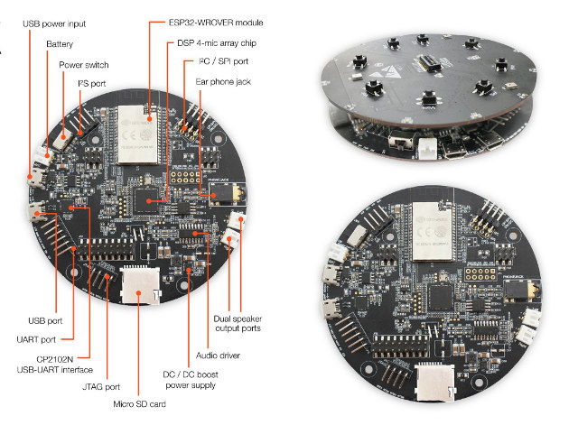
The Shanghai-based Chinese manufacturer Espressif Systems known for their famous ESP8266, is releasing its own voice development kit, the ESP32 LyraTD MSI HDK (Hardware Development Kit” also known as “Audio Mic HDK”, was recently announced on Twitter with this question – “does anyone need something like that?”
The Audio Mic HDK is powered by the ESP32, comes embedded with Wi-Fi and Bluetooth 4.1 LE and as a four-microphone array with dual speaker output ports. It provides support for micro SD Card which can be used for storing audio files, and provides support for – UART, SPI, I2C, I2S, and JTAG through its breakout expansion pins.
Targeting applications in the areas of wireless audio, voice assistant, and home appliances. The kit supports all major cloud voice vendors such as – Amazon Alexa, Google Assistant, and Baidu DuerOS. It supports soft decoder and keyword recognition on the ESP32 processor.
The following are the Espressif Audio Mic HDK specifications:
Wireless Module – ESP32-WROVER module
Connectivity –
802.11 b/g/n WiFi
Bluetooth 4.1 LE
DSP – 4-mic array chip
Storage – micro SD card
Audio –
Audio driver chip
Earphone jack
Dual speaker output ports
4x microphone array with up to 3-meter sensitivity while playing music
Expansion –
I2C/SPI header
6-pin UART header
I2S header
Debugging – USB-UART micro USB interface (based on CP2102N), and JTAG header
Misc –
Power switch
8x keys on top
Power Supply – 5V via micro USB port
It’s unclear when the board is intended to be fully available for the public and the prices are currently unavailable.
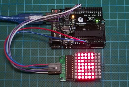
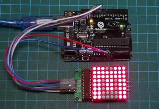
Hi guys, today we will be focusing on displaying mini graphics and texts on an 8×8 LED matrix using the MAX7219 (or MAX7221) LED driver and the Arduino Uno.
The 8×8 LED matrix displays are usually used for the display of symbols, simple graphics and texts. Made of super bright LEDs, they produce low resolution display and can be daisy chained to produce larger displays.
To enable us to control the display easily, we will be using the MAX7219/MAX7221 LED display driver module. Although this driver comes attached to the LED Matrix display that we will be using for this tutorial, its important to treat them separately, so you can understand how the LED driver works and be able to use it in case you are unable to get an 8×8 LED Matrix display that comes with the LED Driver.
Driving an 8×8 (64) LED Matrix with MAX7219 (or MAX7221) and Arduino Uno – [Link]
Back in 2007 Apple released the first generation of iPhone which is considered as the first smartphone as those we use today. Before that, PDAs (Personal Digital Assistants) dominated the market and some even included network connectivity, the ability to send and receive calls, and password unlocking. The iPhone inherited the ability to be unlocked with a 4-digit personal password which allowed users to protect their personal information (photos, contacts, etc.). As it evolved, so did the security concerns regarding stolen phones and the new gained ability of thieves to unlock them despite the password. As a result, smartphone security had to be improved, different operating systems opted for different solutions such as 6- digits passwords, patterns, and finger print unlocking.
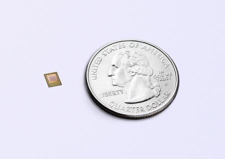
Using finger print to unlock a smartphone is the latest security trend, and almost all smartphones in the market now posses that feature. It is not just safer, but also faster and more convenient for users. However, new researches from New York University and Michigan State University suggest that fake digitally composed fingerprints can easily fool smartphones. The latest iPhone comes with FaceID feature which uses a true Depth selfie camera to scan your face and unlock your phone. Infineon together with pmdtechnologies AG developed a 3D image sensor chip which makes the face unlock feature smarter, faster, and more reliable.
The chip is based on ToF technology which offers advantages in performance, size, and power consumption of mobile devices. The Real3 chip has 38,000 pixels with each one featuring the Suppression Background Illumination circuitry, and includes the receiving optics and VCSEL illumination in a footprint of less than 12×8 mm. It is tuned to work at 940nm infrared light sources which results in improvements in outdoor performance. The product was displayed at CES 2018, and the company claims that they are ready for mass production,
Face recognition is growing in popularity and market forecasts expect an increase to roughly 290 million units in 2019 in smartphones with 3D sensing functionality. This technology seems to be safe, but questions have arisen regarding functionality in different scenarios. For example, can a thief unlock your phone by forcefully pointing it at you? Can an accident victim have problems unlocking their phone? Can the police unlock your phone without a warrant? Smartphone face recognition is still unexplored territory that users along side with developers will have to figure out just as with any other technology. It also offers a wide range of opportunities for developers to make safer payment options.
Unless you are completely new to electronics, you probably must have heard of the household name called “Arduino”. Arduino is an open-source platform used for building electronics projects and one that pioneered the open-source hardware and the DIY maker’s movement. Arduino can sense the environment by receiving input from a variety of sensors and can affect its surrounding by controlling lights, motors, and other actuators. The microcontroller on the Arduino is programmed using the Arduino programming language which you can program to do so many things like switch on your lights when you walk in or send an alert when there is an intruder in your house.
The Arduino Uno is one of the first boards of the Arduino Family and that which fully sparked the Arduino Revolution. The success of this boards in teaching kids, students, enthusiast and even engineers has led to drastic replication of it, often called Arduino Clones or Arduino Compatible board. Arduino Clones are basically Arduino lookalike boards that perform almost the same functionality with the real Arduino but not made by the Arduino team. Some of these Arduino clones comes at a very lesser cost as compared to the $25 of the official Arduino Uno, some even as low as $3.
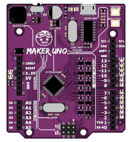
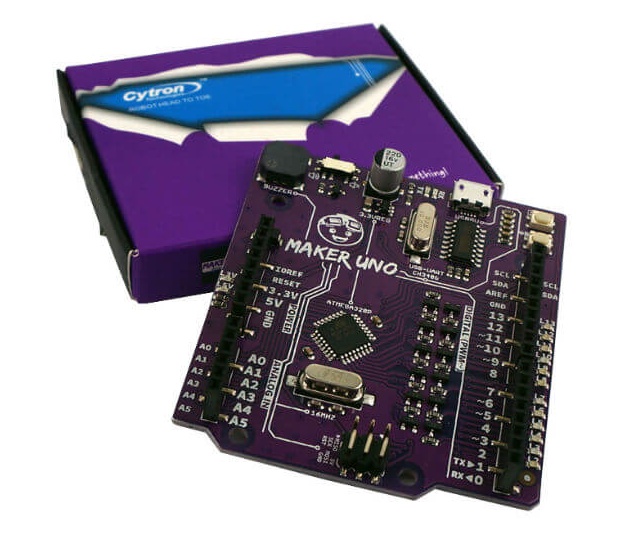
Maker Uno is another Arduino Compatible board released by Malaysia based Cytron Technologies, having launched their first Arduino Uno clone board “Ct Uno” about three years ago. The Maker Uno is purple in color and retails for just $6. It shares close similarities with the standard Arduino Uno with just some few differences. Its termed to be a board designed for students learning coding and microcontroller for the first time. The name Maker is to encourage everyone to be a maker and start building things.
As the Arduino Uno, the Maker Uno is based on the popular Atmega 328P microcontroller can be programmed via it’s USB port. It is also based on the includes standard female headers – means it will easily support most Arduino based Shields.
The traditional DC Jack on the Arduino Uno has been removed from the Maker Uno board and the obviously 5V linear regulator, so the Maker Uno board can only be powered by 5V from the micro USB port or the 5V header pin. It includes a piezo buzzer connected to pin 8 for audio outputs with a selectable switch to disable the buzzer, a micro USB port as compared to the Arduino Uno USB B connector, and a programmable push button. Aside from the standard LED on pin 13, Maker-UNO comes with a programmable LED on every digital pin, from pin D0 to D13.
Maker-UNO combines the simplicity of the UNO Optiboot bootloader the stability of the low-cost FTDI CH340 chip and the R3 shield compatibility of the latest Arduino UNO R3.
The following are some of the Maker Uno Features:
SMD ATmega328P microcontroller(the same microcontroller on Arduino UNO) with Optiboot (UNO) Bootloader
USB Programming facilitated by the CH340
Input voltage: USB 5V, from computer, power bank or standard USB adapter
500mA (maximum) 3.3V voltage regulator
0-5V outputs with 3.3V compatible inputs
14 Digital I/O Pins (6 PWM outputs)
6 Analog Inputs
ISP 6-pin Header
32k Flash Memory
16MHz Clock Speed
R3 Shield Compatible
LED array for 5V, 3.3V, TX, RX and all digital pins
Utilize USB Micro-B socket
Purple PCB!
The Maker Uno is a great board for getting started with coding and electronics. Unlike the Arduino Uno, to start development with the Maker Uno, you will first need to install the CH340 driver first. The Maker Uno is available for purchase at Tindie and Cytron. You can kickstart your Maker Uno board adventure from here.
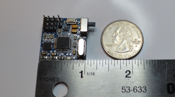
De Martin Cote @ kickstarter.com designed v2 of his gyroscope sensor that is able to track movement on 3-axis. The new board is smaller, lighter, cheaper and has PPM output to connect on your RC remote control. He writes:
Here is the evolution of my successful Gyroscope Sensor. Now smaller, lighter, cheaper and with optional PPM output.
Even more perfect for FPV head tracking, robotics, movement control and why not video games. Based on ATmega328P microcontroller, the 3 axis motion sensor gyroscope allows you to track the movement of the head or arm and replicate it to servos. For Do It Yourself (DIY) home project lover who dreams of doing a head tracking system FPV themselves cheaply.
This system has been specially designed for DIY in electronics or robotics for students to explore electronics or who want their own system, but are less comfortable with advanced programming of accelerometers. You can use one or more axes (X, Y, Z) independently. According to your needs.
Iota V2 – Gyroscope Sensor in tiny dimensions – [Link]
Hi guys, today we will be focusing on displaying mini graphics and texts on an 8×8 LED matrix using the MAX7219 (or MAX7221) LED driver and the Arduino Uno.
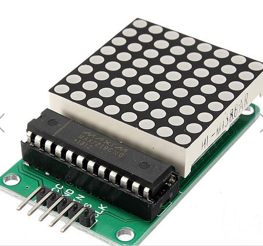
8×8 LED Matrix Display
The 8×8 LED matrix displays are usually used for the display of symbols, simple graphics and texts. Made of super bright LEDs, they produce low resolution display and can be daisy chained to produce larger displays.
To enable us to control the display easily, we will be using the MAX7219/MAX7221 LED display driver module. Although this driver comes attached to the LED Matrix display that we will be using for this tutorial, its important to treat them separately, so you can understand how the LED driver works and be able to use it in case you are unable to get an 8×8 LED Matrix display that comes with the LED Driver.
8×8 LED Display With Arduino
The MAX7219/MAX7221 are compact, serial input/output common-cathode display drivers that interface to microcontrollers and microprocessors to control 7-segment numeric LED displays of up to 8 digits, bar-graph displays, or 64 individual LEDs. Included on the MAX7219 chip is a BCD code-B decoder, a multiplex scan circuitry, a segment and digit drivers, and an 8×8 static RAM that stores each digit. Only one external resistor is required to set the segment current for all LEDs. The MAX7221 is compatible with SPI, QSPI, and MICROWIRE communication protocols, and has slew-rate-limited segment drivers to reduce EMI. Individual digits of the connected LED display may be addressed and updated without rewriting the entire display. The MAX7219/MAX7221 also allow the user to select code-B decoding or no-decode for each digit.
Do note that the 8×8 LED matrix used in this tutorial already comes with the LED Driver attached as its common with most 8×8 LED modules these days. To get it, just follow the link attached to it.
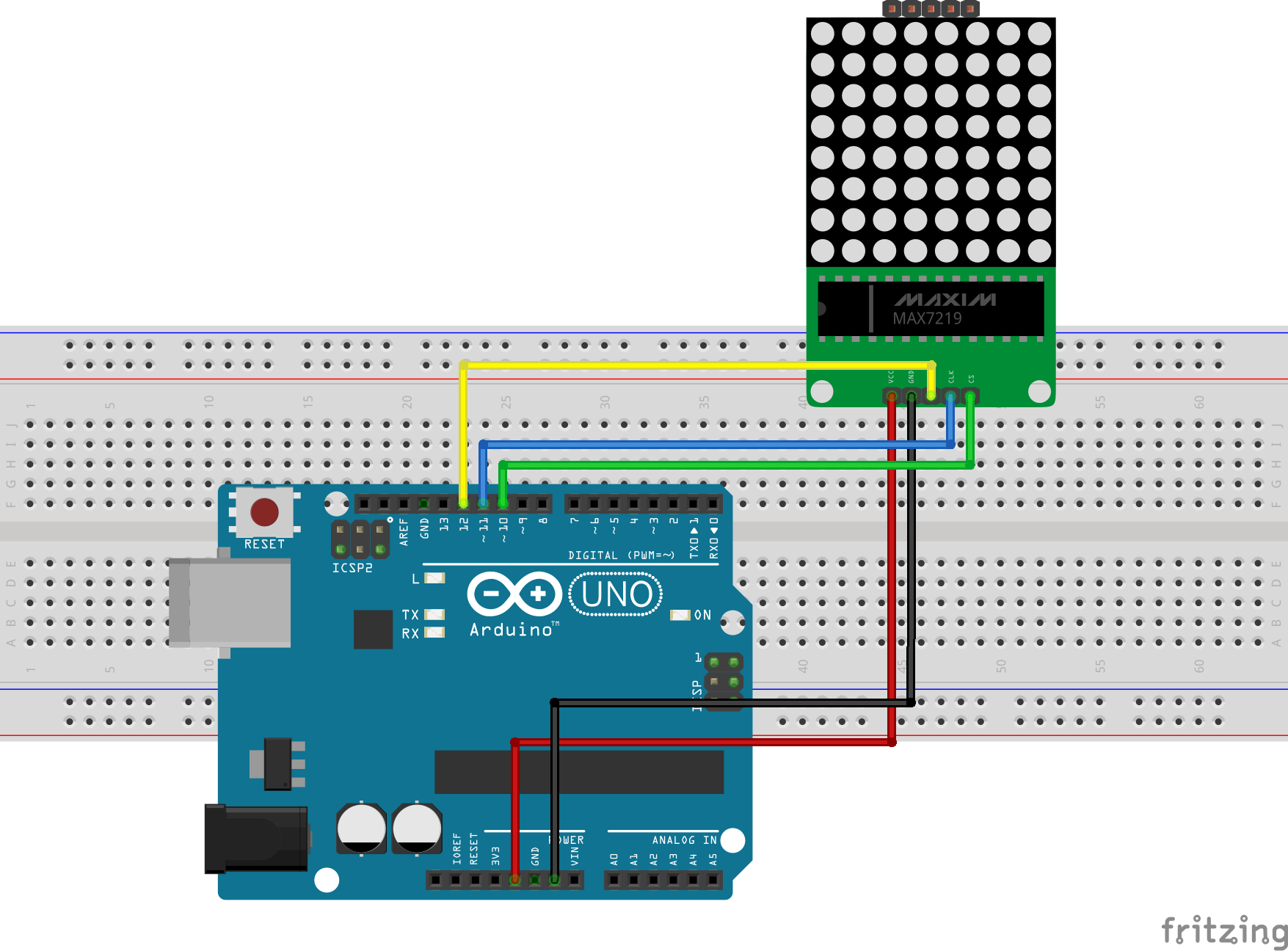
Schematics
Connect the Module to the Arduino as shown in the Fritzing schematics below.
here is a pin map of the connection for clarity.
Display – Arduino
VCC  - 5V
GND - GND
DIN - D12
CS -  D11
CLK - D10
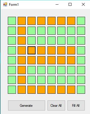
Creating Graphics for Display on the LED Matrix
Before we proceed to writing the code for this project, I would like to show you an easy way of creating the graphics to be displayed on the LED Matrix and generating the byte array that will be used in the code to represent the graphics to be displayed. To do this, we will use a very lightweight software which I found online, called “PixeltoMatrix”.
Highlighting the boxes to draw letter E
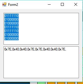
This software allows you draw your graphics by highlighting boxes like some dots connecting sort of game, then generates the byte array which you can then copy and use in your code.
The Byte Array Generated
pretty cool right? I thought so too.
Code
To ensure ease of the coding process, we will use the LEDcontrol library which can be downloaded from here. This Library makes the process of programming the Arduino to drive the LED matrix easy. So as usual, download the library, extract it and copy to your Arduino libraries folder, then start the Arduino IDE.
The first thing we do in the code as usual, is to include the libraries that will be used, then we declare the pins on the Arduino to which the LED Matrix is connected.
//Written by Nick Koumaris
//info@educ8s.tv
//educ8s.tv
#include <LedControl.h>
int DIN = 12;
int CS =  11;
int CLK = 10;
After declaring the pins, we declare the byte arrays that describe the graphics to be displayed. The byte arrays were generated as described in the previous section. The first one, for instance, is the byte array to display a smile.
After the byte arrays for the graphics to be displayed has been created, we then create an object of the LCD control library.
LedControl lc=LedControl(DIN,CLK,CS,0);
Next, we move to the void setup() part of the code. With the library lifting most of the heavy loads we don’t have much to do. The first thing we do in the loop section is call take the MAX7219 out of the power saving mode, then we set the brightness of the display using the lc.setintensity() function, after which we clear the display, making it ready to receive data.
void setup(){
lc.shutdown(0,false); //The MAX72XX is in power-saving mode on startup
lc.setIntensity(0,15); // Set the brightness to maximum value
lc.clearDisplay(0); // and clear the display
}
With this done, we then go to the void loop() function which featured some more declaration of graphics byte arrays, and the display of the graphics on the LED Matrix. The display of a graphics on the LED matrix is done via the function, printbyte(), with the argument of the function being the name of the byte array representing the graphics to be displayed. For example, printbyte(smile) prints the graphics “smile” as described by its byte array.
After displaying the graphics, the delay() function is used to keep the graphics on the LED matrix for a specific number of seconds.
Every other part of the code is a slight modification to things we already know and is easy to follow.
The full Code for the project is available below and also attached in the zip file provided under the download section which can be found at the end of this post.
// Written by: Nick Koumaris
// educ8s.tv
#include <LedControl.h>
int DIN = 12;
int CS = 11;
int CLK = 10;
byte e[8]=     {0x7C,0x7C,0x60,0x7C,0x7C,0x60,0x7C,0x7C};
byte d[8]=     {0x78,0x7C,0x66,0x66,0x66,0x66,0x7C,0x78};
byte u[8]=     {0x66,0x66,0x66,0x66,0x66,0x66,0x7E,0x7E};
byte c[8]=     {0x7E,0x7E,0x60,0x60,0x60,0x60,0x7E,0x7E};
byte eight[8]= {0x7E,0x7E,0x66,0x7E,0x7E,0x66,0x7E,0x7E};
byte s[8]=     {0x7E,0x7C,0x60,0x7C,0x3E,0x06,0x3E,0x7E};
byte dot[8]=   {0x00,0x00,0x00,0x00,0x00,0x00,0x18,0x18};
byte o[8]=     {0x7E,0x7E,0x66,0x66,0x66,0x66,0x7E,0x7E};
byte m[8]=     {0xE7,0xFF,0xFF,0xDB,0xDB,0xDB,0xC3,0xC3};
LedControl lc=LedControl(DIN,CLK,CS,0);
void setup(){
 lc.shutdown(0,false);       //The MAX72XX is in power-saving mode on startup
 lc.setIntensity(0,15);      // Set the brightness to maximum value
 lc.clearDisplay(0);         // and clear the display
}
void loop(){

    byte smile[8]=   {0x3C,0x42,0xA5,0x81,0xA5,0x99,0x42,0x3C};
    byte neutral[8]= {0x3C,0x42,0xA5,0x81,0xBD,0x81,0x42,0x3C};
    byte frown[8]=   {0x3C,0x42,0xA5,0x81,0x99,0xA5,0x42,0x3C};

    printByte(smile);

    delay(1000);
printByte(neutral);
delay(1000);
printByte(frown);
delay(1000);
printEduc8s();
lc.clearDisplay(0);
delay(1000);
}
void printEduc8s()
{
printByte(e);
delay(1000);
printByte(d);
delay(1000);
printByte(u);
delay(1000);
printByte(c);
delay(1000);
printByte(eight);
delay(1000);
printByte(s);
delay(1000);
printByte(dot);
delay(1000);
printByte(c);
delay(1000);
printByte(o);
delay(1000);
printByte(m);
delay(1000);
}
void printByte(byte character [])
{
int i = 0;
for(i=0;i<8;i++)
{
lc.setRow(0,i,character[i]);
}
}
Demo
Upload the code to your Arduino board, you should see something like the image below.
Demo
That’s it for this tutorial guys, don’t forget to leave questions, and comments, in the comments section of the tutorial.
Till next time, Keep Building!
The youtube video for this tutorial is available via the attached link, here
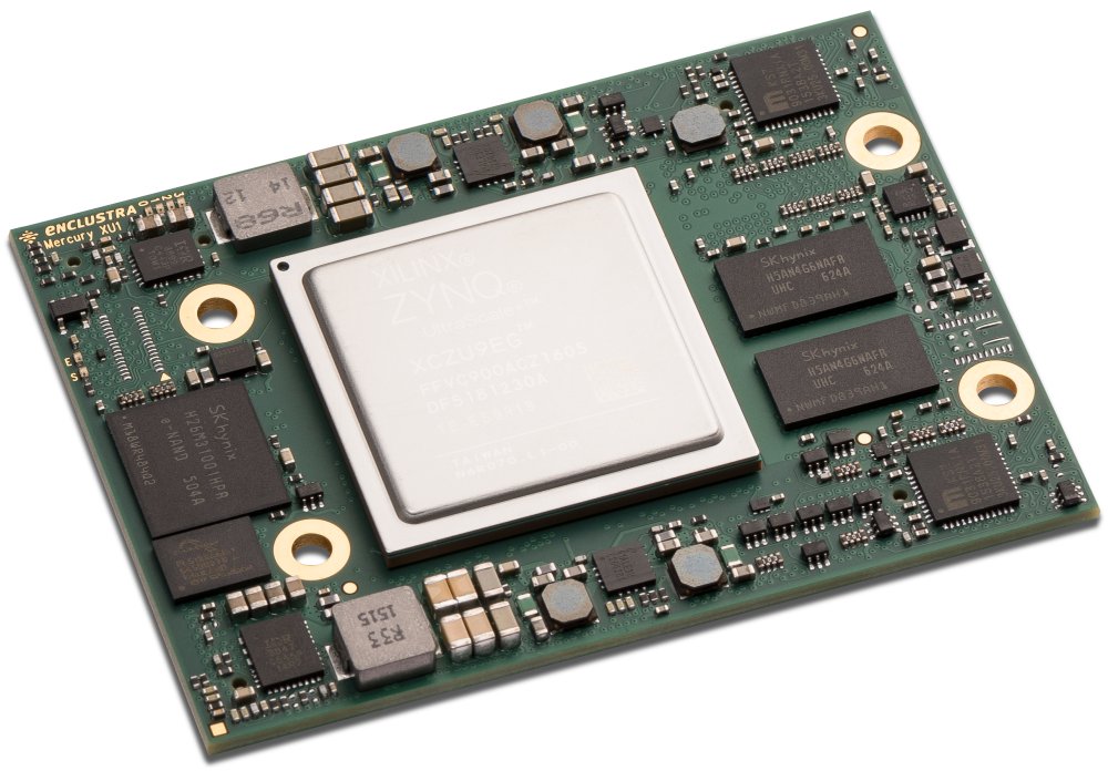
Enclustra’s Mercury+ XU1 is the company’s fastest SoC module based on the Xilinx Zynq UltraScale+ MPSoC. The 74×54mm board accommodates 6 ARM cores, a Mali 400MP2 GPU, up to 4 GB of extremely fast DDR4 ECC SDRAM, numerous standard interfaces, 294 user I/Os and up to 747,000 LUT4 equivalents – all on an area smaller than a credit card.
Built-in interfaces include two Gigabit Ethernet, USB 3.0 and USB 2.0, sixteen MGTs (with speeds of up to 12.5 Gbps), as well as PCIe Gen2 x4. With up to 4 GB of DDR4 SDRAM with bandwidths of 19.2 GByte/s and ECC, as well as 16 GB eMMC flash memory, the Mercury+ XU1 will handle even the heaviest of resource-hogging applications. The module is available in both commercial and industrial temperature ranges, and needs just a single 5-15 V supply for operation.
Xilinx Zynq UltraScale+ SoC module smaller than a credit card – [Link]
A group of researchers from the University of Colorado in Boulder (US) is working on the next generation of robots. Instead of the metallic droids concept, these robots are made from soft materials that are more similar to biological systems. Such soft robots hold a huge potential for future applications. They can adjust to dynamic environments and also suitable for close human interaction. Christoph Keplinger from the University of Colorado said,
We draw our inspiration from the astonishing capabilities of biological muscle,
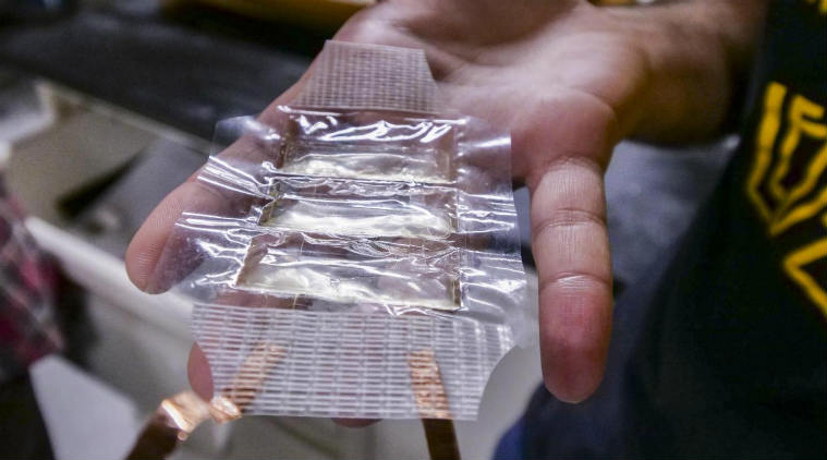
The soft robots, including the muscle actuator, can perform a variety of tasks
The newly developed class of soft, electrically activated devices are capable of simulating the expansion and contraction of actual muscles. These devices can be constructed from a wide range of low-cost materials. They are able to self-sense their movements and self-heal from electrical damage.
They developed hydraulically amplified self-healing electrostatic (HASEL) actuators which eliminate the bulky, rigid pistons, valves, pumps and motors of conventional robots. The soft structures of HASEL react to applied voltage with a wide range of movement. According to the study published in the journal Science Robotics on January 5, these flexible robots can perform a variety of tasks. They can handle delicate objects like raspberry or raw egg, as well as lift heavy objects. Keplinger said,
HASEL actuators synergize the strengths of soft fluidic and soft electrostatic actuators, and thus combine versatility and performance like no other artificial muscle before,
He also added,
Just like a biological muscle, HASEL actuators can reproduce the adaptability of an octopus arm, the speed of a hummingbird and the strength of an elephant.
HASEL actuators can simulate the strength, speed, flexibility, and efficiency of biological muscle which may enable artificial muscles for human-like robots. HASEL can make next generation of prosthetic limbs more cost-effective and reliable. This is an important step forwards for soft robotics.
The team is already working on new HASEL actuators that would work with five times lower voltage levels than those described in the studies. The voltage published in the papers is similar to the low-current shock one might get from static electricity, and it’s not hazardous to humans.
The work of this researchers promises a huge improvement in the world of robotics and prosthetic limbs. Their dream is to create robotics that is lifelike. More information can be found in an article appeared in Science recently.
Asus, the Taiwanese computer and electronics household name, in February last year entered into the maker’s world with their introduction of the original Tinker Board. The Original Tinker Boards was believed to out-sit the household Raspberry Pi, even though the original tinker board was way better than the Raspberry Pi in all aspect of hardware functionality, it was lacking in the software and community department. Raspberry Pi is great not for it’s easy to use hardware but mostly for its community. In the maker’s world, the community is the most important thing and this is where Raspberry Pi and the like of Arduino has excelled excellently.
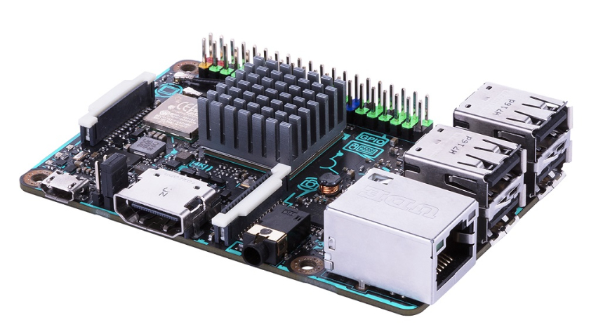
The Asus Tinker Board S
Fast forward to 2018, Asus is back with a new and expected more powerful board called the “Tinker Board S”. The new and improved Tinker Board S is a single board computer (SBC) that offers greater durability, better stability and an overall improved user experience for DIY enthusiasts and makers everywhere.
Announced at the CES 2018, the Tinker Board S is a single board computer that looks like the Raspberry Pi form factor, but with an overall improved board. As with the original Tinker Board, the Tinker Board S comes in a flashy looking dark board. The S board is equipped with the same Rockchip RK3288 quad-core cortex processor on the original Tinkerboard running at 1.8Ghz, compared to the quad-core 1.2GHz Broadcom processor in the Raspberry Pi 3.
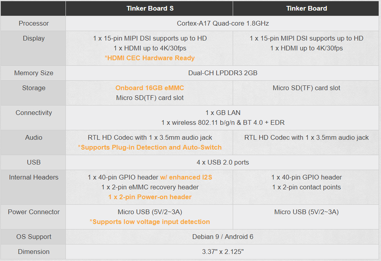
The Tinker Board S comes with a lot of built-in storage and comes with a whopping 16GB of eMMC storage, enough to install an Android or Linux operating system and still have free space left. The S board also includes a microSD card slot, so you can always increase the storage as you like. The S board has 2GB of RAM memory based on the faster DDR3 technology, a double of the 1GB of the Raspberry Pi 3, and the slower DDR2.
Tinker Board S Specs
Like ASUS’ previous board, the new Tinker Board S has a 40-pin GPIO color-coded header block compatible with the Raspberry Pi. and comes with 4 USB 2.0 ports. For better user experience, Tinker Board S is HDMI-CEC-ready for complete video entertainment, with which you can control the hacker board and TV with a single remote. It can handle a 4K display at 30fps using the onboard HDMI jack.
The Tinker Board S also features a Gigabit Ethernet for internet and network connectivity. Just like the Raspberry Pi 3, the S board comes integrated with an onboard Wi-Fi and Bluetooth 4.0. The S boards include an integrated IPEX antenna header to which allows for easy antenna replacement or upgrades.
The Tinker Board S is the latest in a long line of more powerful alternatives to the Raspberry Pi, and if you are just getting started with single board computers (SBC), the Raspberry Pi 3 is going to be the best choice. The S board is expected to be available in early 2018 with a price tag of $79.99. For more information about the Asus Tinker Board S, visit the official product page here.