The Intel Apollo Lake SoCs officially known as the Intel Atom® processor E3900 series, Intel® Celeron® processor N3350, and Intel® Pentium® processor N4200 platform empowers real-time computing in digital surveillance, new in-vehicle experiences, advancements in industrial and office automation, new solutions for retail and medical, and more. Intel which has also pioneered the Embedded NUC (eNUC) through its Intel NUC system is paving the way for the development of Next Generation Single Board Computers (SBCs).
PortWell, the makers, and innovator of several industrial embedded computing solutions who just released the recent Pico ITX Apollo Lake SoC board have just released the Portwell “WUX-3455” board, a small form factor embedded system board featuring the Intel Celeron Processor J3455, known as Apollo Lakes and also part of their WUX-3350 mini PC board series.
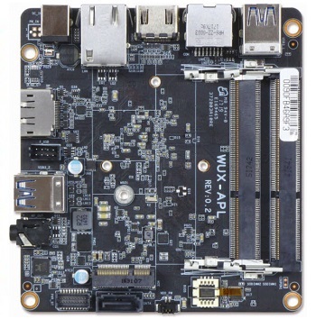
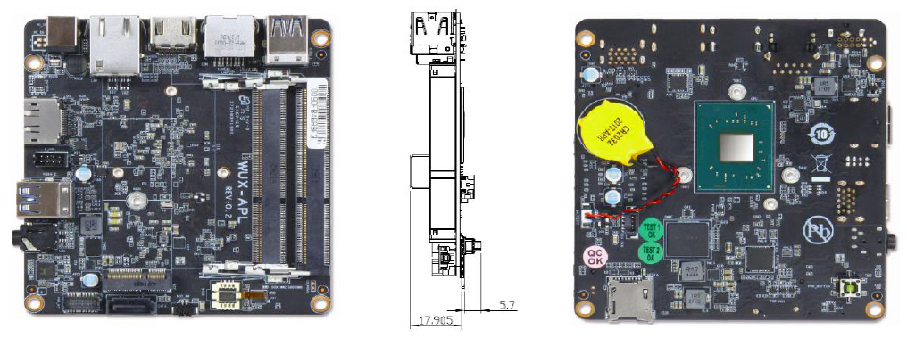
Portwell’s WUX-3455 is a 4×4-inch (101.6mm x 101.6mm) Embedded NUC form factor board, based on the Intel Celeron J3455 Processor plus DDR3l SO-DIMM supporting up to 8GB 1866/1600 MT/s, up to 6x USB ports 3.0 and 2.0, up to 64GB eMMC 5.0 flash storage, onboard microSD 3.0 Socket, one COM port using the RJ45 connector for RS-232, one DisplayPort (DP) and one HDMI with resolution supporting 4K videos.
With a display port and one HDMI port offering a resolution of about 4096 x 2160 and an onboard Realtek ALC255 driven audio I/O, the Portwell WUX-3455 board isn’t shy away from producing 4K videos with surrounding audio, and enough multiple storage interfaces to hold content. The board is equipped further with Gigabit Ethernet, RS-232 ports and enough USB Ports, data communication is made easy. It provides an M.2 slot support, for various wireless options, and a TPM chip is optional.
The Portwell WUX-3455 delivers robust performance, yet it operates with thermal design power (TDP) under 6W/10W for fanless applications. Going with the quad-core Celeron J3455 gives 10W TDP at about 1.5GHz to 2.3GHz, the quad-core Pentium N4200 generates 6W TDP at about 1.1GHz to 2.5GHz, and the dual-core Celeron N35550 generates 6W TDP at about 1.1GHz to 2.5GHz. It also supports a wide voltage of power input from 12V to 19V and a 0 to a 60oC temperature range for rugged applications.
The following below are some of the specifications for the WUX-3455 SBC:
Memory – up to 8GB DDR3L-1866/1600/1333MHz via 2x SODIMMs
Storage Options –
1x SATA III
1x MicroSD 3.0
Up to 64GB onboard eMMC 5.0
Display & Audio:
HDMI 1.4a port at up to 3840 x 2160
DisplayPort at up to 4096 x 2160
Intel HD Audio and Realtek ALC255 HDA codec
Audio jack with line-out or mic-in
Networking — 1x GbE port (Realtek RTL8111H)
Others:
4x USB 3.0 ports on the rear I/O
2x USB 2.0 ports onboard with pitch 2.0 header
RS232 port
Expansion — M.2 E+A key for WiFi, Bluetooth, 3G, 4G
Other features — Watchdog; hardware monitoring; optional TPM 2.0
Power — 12-19VDC input jack
Operating temperature — 0 to 60°C
Dimensions — 101.6 x 101.6mm (4×4-inch eNUC form factor)
The PortWell WUX-3455 board can find applications the areas of digital signage in public spaces (stadiums, museums, transportation systems, corporate buildings, healthcare facilities, retail stores, hotels, restaurants, and more), manufacturing, industrial automation, office automation, video analytics, security surveillance, to end-to-end solutions for the ever-evolving and ever-expanding IoT use cases.
The WUX-3455 is available through Portwell, Arrow Electronics, and Avnet. More information about the WUX-3455 may be found in the WUX-3455 announcement.
Our friends at educ8s.tv uploaded a new video. It’s about Waveshare 1.54″ e-paper display:
Dear friends welcome to this Arduino E-Paper display tutorial. In this video, we are going use this small e-paper display with Arduino for the first time and talk about its advantages and disadvantages.
Hi guys, continuing on our recent path of building really cool stuffs based on the Nokia 5110 LCD display, today we will be building a DIY Lux (or light) meter using the highly sensitive BH1750 light sensor.
In photometry, illuminance is the total luminous flux incident on a surface, per unit area. It is a measure of how much the incident light illuminates the surface, wavelength-weighted by the luminosity function to correlate with human brightness perception. Similarly, luminous emittance is the luminous flux per unit area emitted from a surface. Luminous emittance is also known as luminous exitance.
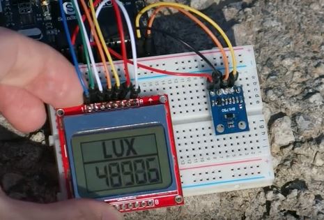
Lux is a measurement of the overall intensity of light within an environment for any given area or distance from the source or lux is the amount of light in an environment perceived by the human eye. The Lux meter is thus, a device used to measure the light intensity within an environment and its exactly what we will be building during this tutorial.
DIY Light (Lux) Meter using BH1750 sensor, Arduino and Nokia 5110 – [Link]
Hi guys, continuing on our recent path of building really cool stuffs based on the Nokia 5110 LCD display, today we will be building a DIY Lux (or light) meter using the highly sensitive BH1750 light sensor.
Illuminance (measured in LUX) is the total luminous flux incident on a surface, per unit area. It is a measure of how much the incident light illuminates the surface, it is wavelength-weighted by the luminosity function to correlate with the level of human brightness perception.
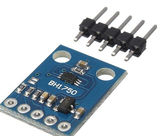
BH1750 Sensor Module
Lux is a measurement of the overall intensity of light within an environment for any given area or distance from the source or lux is the amount of light in an environment perceived by the human eye. The Lux meter is thus, a device used to measure the light intensity within an environment and its exactly what we will be building during this tutorial.
Below is a picture of the device taking outdoor readings on a bright morning.
The BH1750 sensor is a digital Light Sensor capable of measuring light intensity with a great degree of accuracy and over a large range. It communicates with microcontrollers or processors to which it is connected via the I2C bus interface. This module is the most suitable to obtain the ambient light data and it is commonly used for adjusting LCD and Keypad backlight power of Mobile phones.
Some of the features of this sensor include;
I2C bus Interface ( f / s Mode Support )
Spectral responsibility is approximately human eye response
Illuminance to Digital Converter
Wide range and High resolution. ( 1 – 65535 lx )
Low Current by power down function
50Hz / 60Hz Light noise reject-function
It is possible to select 2 type of I2C slave-address.
Adjustable measurement result for influence of optical window ( It is possible to detect min. 0.11 lx, max. 100000 lx by using this function. )
Small measurement variation (+/- 20%)
Required Components
The following components are needed to build this project;
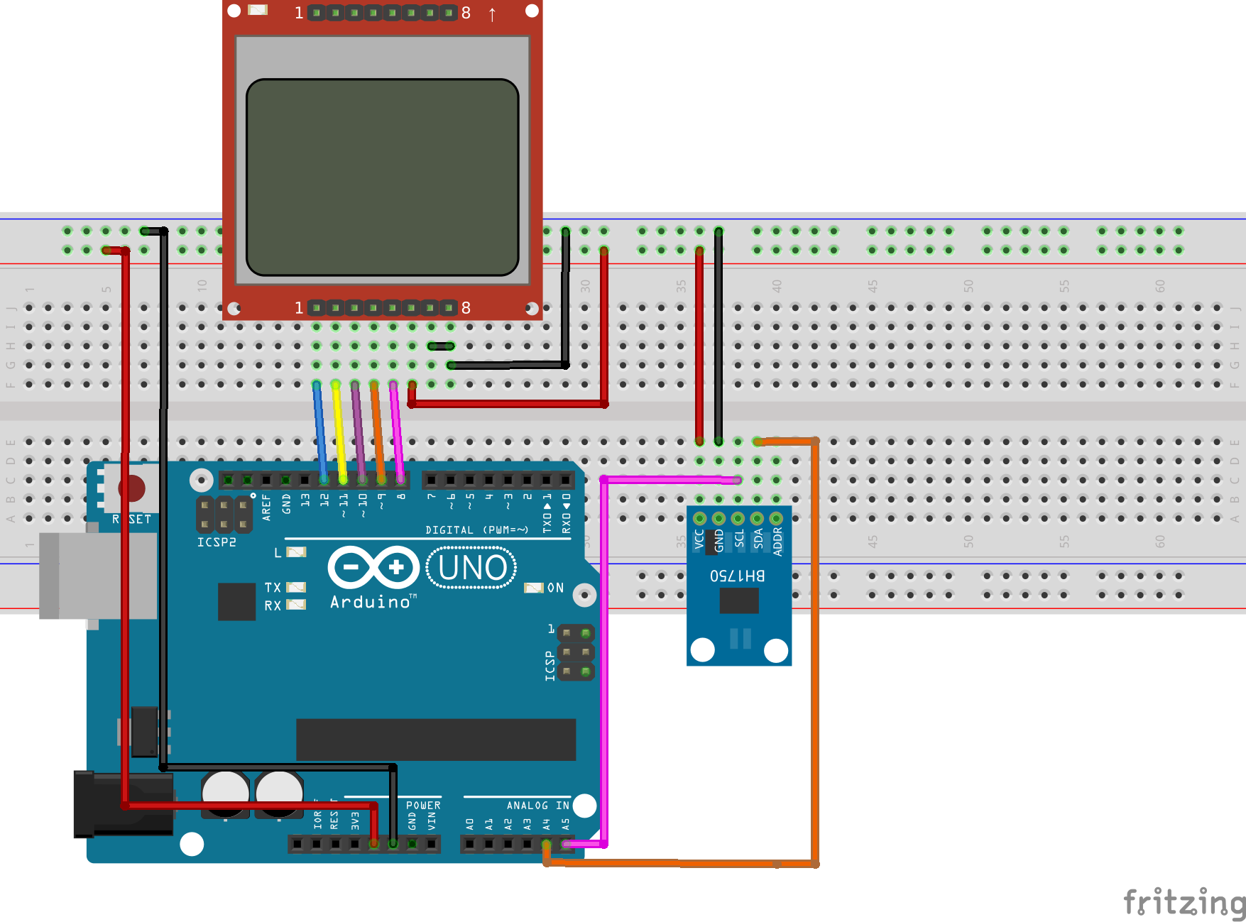
Connect all components as shown in the Fritzing schematics below;
Schematics
The BH1750 light intensity sensor module has a 16-bit analog to digital converter built-in that can directly output a digital signal over I2C communication protocol, thus the device is connected to the Arduino I2C pins which are located on analog pin 4(SDA) and 5(SCL). The connection is further detailed below.
BH1750 – Arduino
vcc - 5v
GND - GND
SCL - A5
SDA - A4
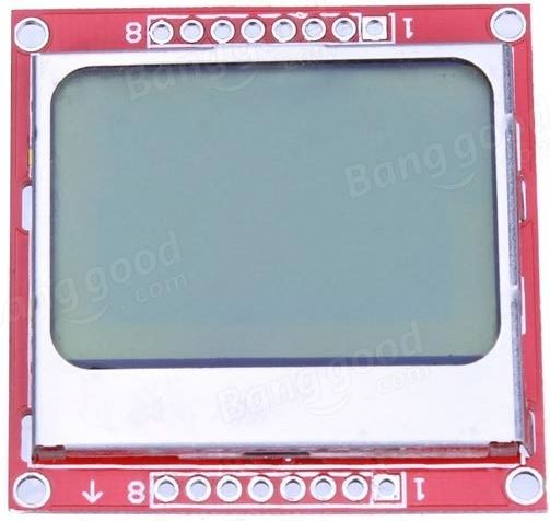
Nokia 5110 LCD
For the Nokia 5110 LCD module, a detailed tutorial has been made before on how to use the module with the Arduino and can be found here. It will help you better understand how the Nokia 5110 connection with the Arduino works. For this project, however, the pin connection of the Nokia 5110 LCD to the Arduino (as shown in the schematics) is given below;
Double check your connections to be sure you got everything right before proceeding to the code.
Code
Like most of our projects, In order to easily program our arduino to work with the BH1750 light sensor, we need the BH1750 arduino library. For this tutorial we will be using the library which can be found here. Download the library, and install in your arduino IDE by unzipping and copying it to the arduino library folder.
Since we are using the Nokia 5110 LCD display, we will also need the library which can be downloaded from here and installed in the same way as the BH1750 library. To know more about the Nokia 5110 LCD, check out the tutorial on it which can be found above.
With our libraries all installed, we are ready to launch the Arduino IDE and get to work.
The code file for this project, attached in the zip file at the end of this tutorial, contains three files; the Arduino code, the hex file for the graphics displayed on the screen when the device is powered and the UI design for the display. A detailed tutorial on how to prepare graphics and load them on to the Nokia 5110 LCD is found here, It will be of immense help when it comes to understanding how to load graphics to the display.
The first thing we do in our code includes the libraries that we will be using, which are the BH1750 library, the Nokia 5110 LCD library and the Arduino Wire LIbrary which is needed for the I2C communication.
//Written by Nick Koumaris
//info@educ8s.tv
//educ8s.tv

#include <LCD5110_Graph.h>
#include <Wire.h>
#include <BH1750.h>
Next we declare the pins to which the lcd is connected to, and also specify the font tupe and the name of the graphics and ui files.
Next, we create an object of BH1750 and also declare the string variable which will hole all the light information from the sensor.
BH1750 lightSensor;
String light;
With this done, we are then ready to move to the setup function, the commands under this section seem quite easy to grab to me. I2C communication system is started, followed by initializing the LCD, font settings, and the display of the splash screen icon. The system waits for a couple of seconds before proceeding to the loop section to give the splash screen enough time on the display.
With the setup function all done, we are now ready to proceed to the loop function.
The loop function is pretty basic. the first command initializes the string length setting it to 0. The next command reads the light intensity reading from the sensor then the screen is cleared, the UI uploaded to the screen and the sensor data is printed to the screen after conversion.
A delay is set to allow the function to take some time in between readings.
Feel free to copy and paste in the Arduino IDE once setups like library installation etc are done.
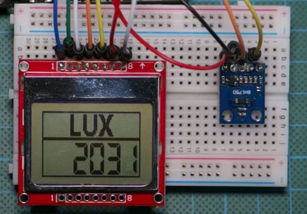
Demo
Copy the code, paste in the Arduino IDE, and upload to your arduino board, you should get an output like the image below on your screen. Don’t forget to include the icon file in the Arduino sketch folder.
Demo
That’s it for this tutorial guys. As usual, let me know if you have any questions via the comments section.
The youtube video of this tutorial is available here.
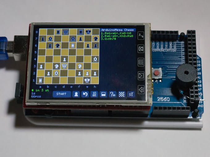
Chess processor with GUI dedicated for Arduino Mega. by Sergey Urusov
After some my Arduino project remains unclaimed touchscreen, so I decided to realize my chidhood dream to create a chess program. After a couple of months it wins me, but it is not big deal because i do not have any chess rating, just amateur.
This project uses Arduino Mega 2560 because of lack of operative memory on Uno, 2.8 inch touchscreen, passive buzzer, and about 2000 lines of code.
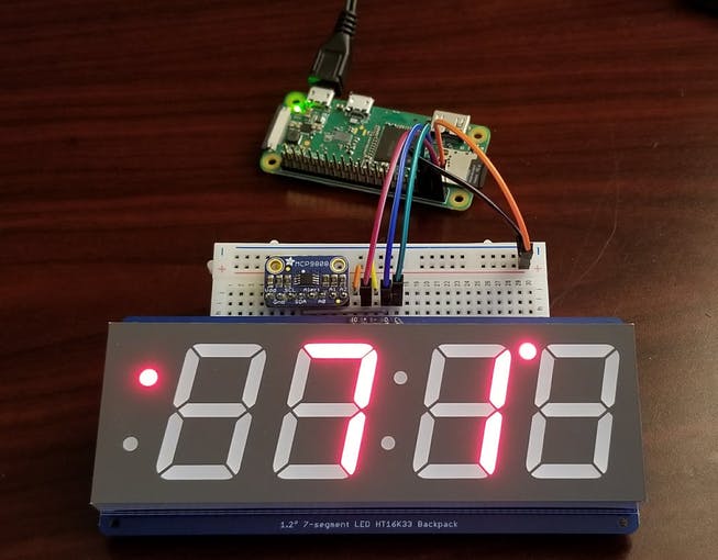
A Raspberry Pi clock with outside temperature display using OpenWeatherMap and inside temperature display using a MCP9808 sensor. By Jeremiah Mattison
This project is for a building a digital clock that includes temperature display. It uses OpenWeatherMap to retrieve outside temperature information and a MCP9808 sensor for inside temperature.
Wearables are devices that incorporate and interact with different parts of our bodies and perform a specific task. The tasks can be to improve our health (count steps, heart rate etc.) or to make our life easier (GPS, smartwatches etc.). Technology industry has dominated the wearable market since its easier for a technology company to produce technologic devices, but other companies have joined the trend and now companies in the textile, fashion and medical industry started producing their own wearables with specific purposes. L’Oréal the world leader on makeup, cosmetics skin care etc. has now joined the race.
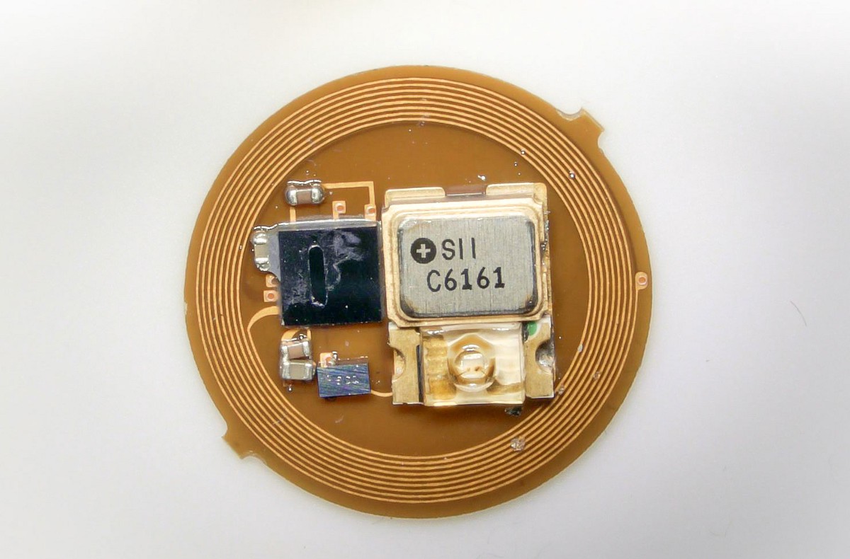
In a research project with Northwestern university, the world´s smallest wearable was created. Measuring less than an M&M in circumference and weighting less than a raindrop this device was designed to measure UV exposure of the user to reduce skin cancer by modulating their exposure to the sun. UV Sense has no battery, no moving parts, its waterproof, and it can be attached to any part of the body preferably a location with good sun exposure.
The device connects to an app that shows you the exposure you have had in a day or over a period. Also, the app can be configured to send notifications when users exceed daily safe sun limit.
According to the skin cancer foundation “Each year in the U.S over 5.4 million cases of nonmelanoma skin cancer are treated in more than 3 million people, and each year there are more new cases of skin cancer”, but with this device skin cancer could be prevented instead of treated. The researchers at Northwestern have received roughly 2 million grant from the National institutes of Health to deploy fingernail UV sensors.
The device is undetectable which will encourage people to use it, and as it requires no batteries, users do not need to worry about charging the device or forgetting to do so. This means that people can now be warned about sun exposure and will be able to take measures to prevent diseases with no effort at all. The same research team is also working on other devices that could help check other health aspects to increase awareness about different diseases and the daily activities that may cause them.
Over the last few years, there has been an unprecedented growth in the consumer electronics industry. The smartphones, fitness trackers, Smart homes devices, wearables, earbuds, VR/AR, and much more have fostered this growth.
The Smartphone proliferation has been a key factor in the global consumer electronics market size, smartphones have become way better, faster and even cheaper. The Internet of Things (IoT) has promised us more incoming and it’s estimated that we will have up to 21 billion connected devices by 2020. Technological advancements like the emergence of 4G and 5G technologies are expected to drive this demand. Despite all these advances in technology, one function remains chained to the wall – Power.
The laptops, tablet, phones, smart hubs, fitness trackers and others still require being powered. Even, though they are mostly battery powered and could last for a couple of days (without much activity), they all still need to be tied to a plug socket for hours to be recharged. Power has been a major source of concern and people have been dreaming about the potential of wireless charging their devices.
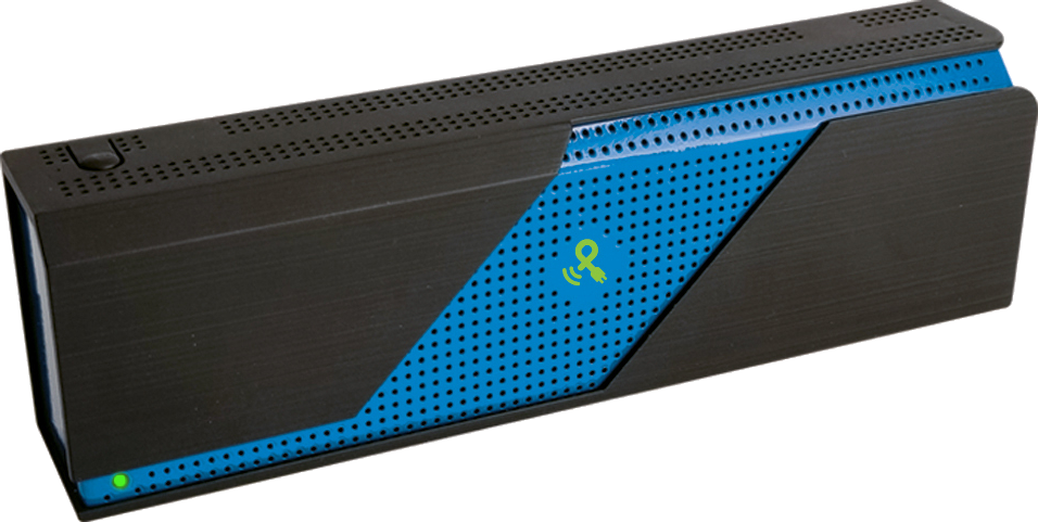
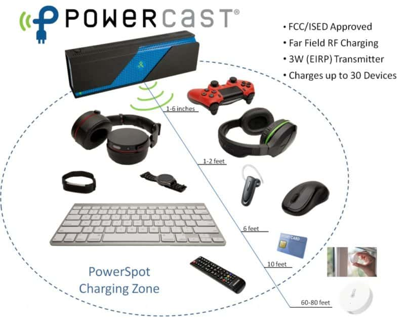
Powercast PowerSpot Transmitter
Wireless charging has been an interesting topic in the past few years with major advancement made in wireless charging smartphones up to a few centimeters using charging platforms. Like Energeous Wattup that charges up to 3 feet away, Powercast has introduced PowerSpot – a system that will allow devices to be wirelessly charged at up to 80 feet away.
Powercast a leading provider of RF-based wireless power technologies, has unveiled the PowerSpot. Similar to Wi-Fi, devices charges in the range of the PowerSport 3W transmitter, and will automatically turn off when full. PowerSpot charging technology needs no charging platform or direct line of sight as we have seen in Qi charging platforms and has already received approval from both the U.S.-based FCC and Canada-based ISED.
Powercast’s transmitter uses the 915 MHz ISM band to send power to a Powercast receiver chip called “The PowerHarvester” in a device, which converts the transmission to DC to “directly power or recharge” an enabled device at up to 80 feet for devices with low power need. The PowerSpot transmitter uses Direct Sequence Spread Spectrum (DSSS) modulation for power and Amplitude Shift Keying (ASK) modulation for data and includes an integrated 6dBi directional antenna with a 70-degree beam pattern.
PowerSpot charging zone
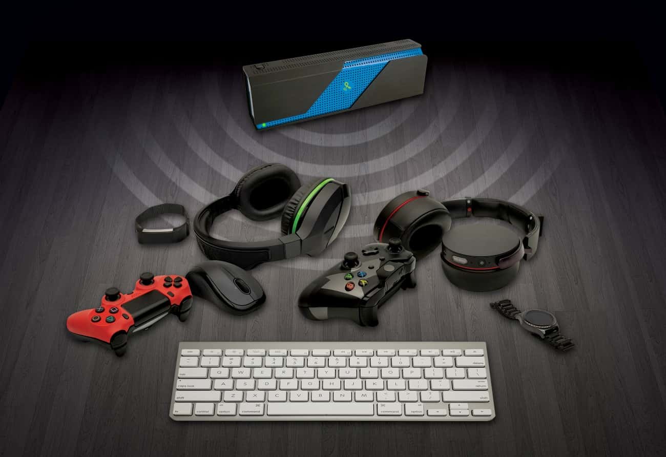
Game controllers, smartwatches, fitness bands, or headphones will charge best up to two feet away; with keyboards and mice up to six feet away. TV remotes and smart cards charge well up to 10 feet away; with low-power devices like home automation sensors getting sufficient charging power up to 80 feet away.
Powercast is expecting a $100 retail on the transmitter with a projected $50 average price when it reaches mass production. It will be available in the 3rd quarter of 2018 or early 2019.
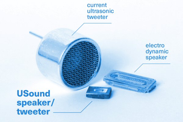
STMicroelectronics along with the audio company USound has created the first MEMS (Micro ElectroMechnical Systems) micro-loudspeaker based on semiconductors. It’s the smallest loudspeaker in the world, but it can produce a powerful noise. MEMS makes it possible. The speakers are being presented at CES 2018 in Las Vegas.
MEMS loudspeaker with extremely small dimensions along with low power consumption and good sound quality.
In the audio world, the electromechanical capabilities of MEMS have only been used to build tiny microphones. Speakers, on the other hand, still rely on traditional dynamic design principles. It has taken almost 150 years for semiconductor technology to replace Werner von Siemens’ superior loudspeaker principle in 1877 with something newer. The Coil-magnet combinations are still being used in smartphones, wearables, and headphones to produce sound.
We can understand the working principle of MEMS speaker very briefly here. At first, thin piezoelectric layers are applied to a semiconductor(Silicon). An electric signal is sent to the piezoelectric layer allowing the diaphragm connected to it vibrate. Eventually, the mechanical principle resembles that of a normal Coil-magnet loudspeaker. The sound is created by the vibration in the diaphragm. However, the magnet and coil are replaced by a piezo element. By applying this new technique, USound’s MEMS version appears to offer significant advantages when it comes to distortion and THD or Total Harmonic Distortion.
The MEMS loudspeaker developed by USound has dimensions of just 5 x 7 x 2 mm and has a frequency range of 2 to 15 kHz. It takes up half the space of its predecessors and needs only 20 percent of the energy that they do. The above figures are convincing enough for the speaker to be a perfect fit for mobile applications such as wearables and smartphones.
According to the manufacturer, these tiny speakers are the thinnest in the world. It has less than half the weight of a conventional Coil-magnet speaker. Most suitable applications include in many portable devices such as headphones, over-the-ear earphones, and more. With the help of this new speakers, augmented reality headsets or virtual reality systems can be more compact and comfortable. Innovative features also enable 3D sound production with striking accuracy. Its high efficiency reduces energy consumption and can easily be operated with much smaller and lightweight batteries. Higher efficiency results in less heat generated making systems operate cooler than ever before.
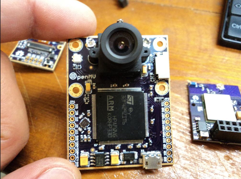
MV is the ability of a computer to see using analog to digital conversion and digital signal processing. The key characteristics that make a machine vision module better are sensitivity and resolution. These systems allow machines to see a broader spectrum of wavelengths such as x-rays, infrared or UV light. Nowadays, it is mainly used for object recognition, signature identification, material inspection, medical image analysis etc. Machine vision modules tend to be expensive which make them difficult to access for makers and hobbyists. OpenMV is a python powered machine vision module that aims at making MV accessible to beginners.
OpenMV was created by Hackaday user i.abdalkader and he worked towards making it affordable, small, open source and user friendly. It is programmable in python 3, and includes image processing libraries to make it easier. It is Based on STM32F ARM Cortex-M Digital Signal Controllers (DSCs) running at 168-216MH, and has an ATWINC1500 FCC Certified Wi-Fi module which can transmit data at up to 48Mbp. The image sensor used was a OV965x and a OV2640. Additionally, it has 512 KB of RAM and consumes 120 mA.
The libraries included give the MV the ability to detect shapes, faces, QR and barcodes, and it also has ORB key points detector, template matching with normalized cross correlation and more. The OpenMV includes I/O headers to connect shields to extend it´s capabilities. The IDE includes many features for image processing and it is based on QT creator. OpenMV has a micro SD card socket which allows for recording data, and the device measures 45 mm in length, 36 mm in width, 30 mm in height and only weights 16 g.
Few prototypes are already on pre-order for beta testing for $65 dollars on this website, they will only be selling about 10-30 of them. It has already been funded in Kickstarter with a huge success in 2015. Some applications might include drone flying, thermal/night imaging, line detection etc.
For beginners, this device could be a game changer for learning about machine vision, and creating projects. The easy to use IDE helps the user understand and code, but at the same time its open for users to modify and create as they see appropriate. The Wi-Fi module expands the capabilities and possibilities for using it, and the fast USB computer communication makes the device easy to work with. For an advanced use it has a long way to go, which includes improvements in image detection and analysis. The complete version is still not on sale, and a date has not been announced, but the project keeps being improved to provide users with a completely functional device and IDE.