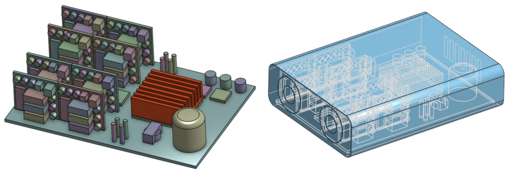
Munich, January 9, 2018 — SimScale is announcing a free webinar on 24th of January to teach electronics engineers how conjugate heat transfer simulation in the cloud can help better investigate the thermal response of electronic packaging.
In such an innovation-driven and competitive industry, engineers deal with increasingly stringent thermal requirements due to the rapid increase in high-power density electronics. Thermal integrity is one of the most important considerations for electronics packaging or enclosures that affect the product lifecycle. The thermal impact on the electronic packaging is a key factor in material selection, cooling and form-related decisions that eventually determine the weight, size, and cost of the final design. It is vital for designers to determine the heat signatures of their system. Continue reading “SimScale is Teaching Electronics Engineers How to Test Designs with Cloud-based CFD”
This is an accurate milliohm meter with a maximum resolution of 0.1mOhm. The design is very simple, the whole assembly can be built in a couple of hours once all the parts are gathered. It is based on a precision current sink and a high-resolution ADC controlled by an Arduino Nano V3. It uses a Kelvin connection with the resistor under test to exclude the resistance of test leads from the measurements. It can be very useful for measuring small resistors and the resistance of PCB traces, motor coils, inductance coils, transformer coils, or calculate the length of wires.
How to overclock the Raspberry Pi device? Don’t matter if you are looking for the way to overclock the Raspberry Pi 3 or overclock the Raspberry Pi 2 – the algorithm stays the same.
The only thing should be taken into consideration is that the Raspberry Pi 3 has significantly improved processor performance compared to previous models. Through various techniques such as overclocking and overvoltage, we can get even more power out of the Raspberry Pi 3. While Raspberry Pi 2 device will always be a little bit behind on performance due to basic technical peculiarities.
Overclocking, basically, is the way to boost Raspberry Pi hardware performance by tuning up several device parameters. For that, additional hardware and special skills are required. Also, you’ll need to implement several tests to make sure of changes to take effect as well as keep your device from damage.
As you have already understood, the overclocking of your Raspberry Pi 3 exercises some risks. What are they and how to avoid them, read in this article on the link.
Amazon’s Alexa is an intelligent voice-controlled personal assistant launched in 2014 and has been on an increasing demand ever since. First integrated into the Echo, the Alexa platform has been an exponential growth in the consumer industry.
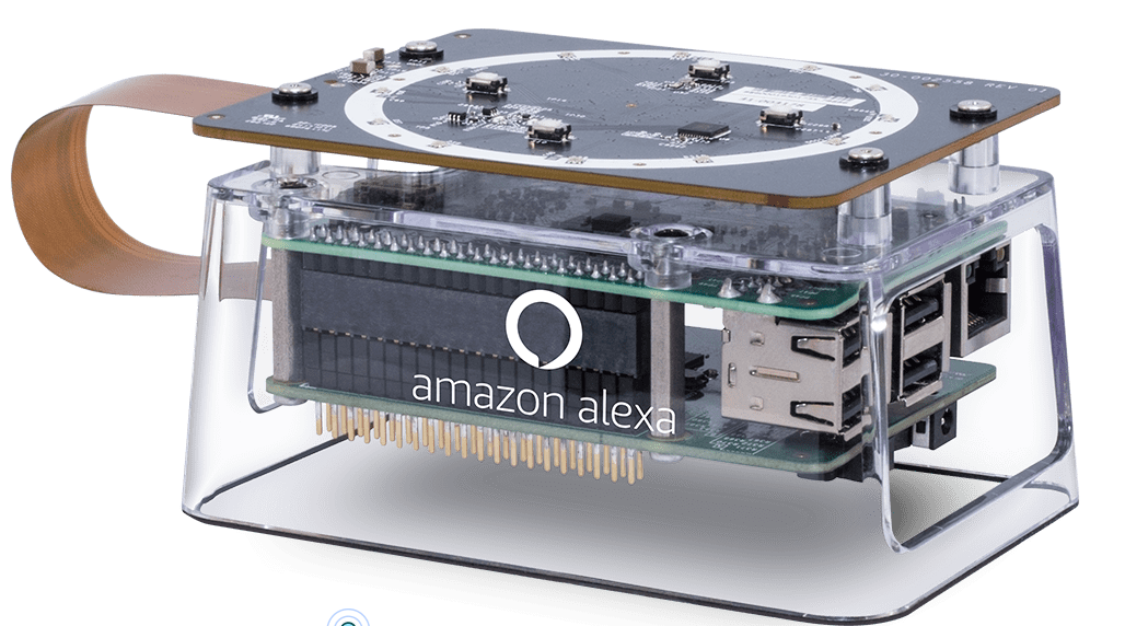
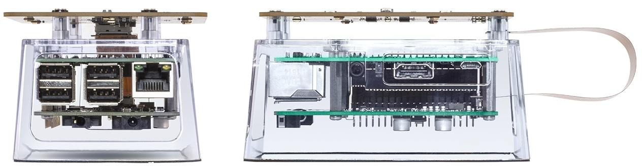
Amazon’s Alexa Premium Far-Field Voice Development kit is a kit released by Amazon that will allow manufacturers to add high-quality Alexa voice experiences into their products, allowing Amazon to integrate Alexa into hundreds to thousands of products without necessarily building the products themselves.
This kit provides support for 360o tabletop far-field voice activation applications, as well ass applications that require voice-activation from one direction. It incorporates Amazon’s proprietary software and algorithm technology for “Alexa” wake word recognition, beam forming, noise reduction, and acoustic echo cancellation, and accurate far-field voice recognition in noisy environments and from long distances.
The development kit includes:
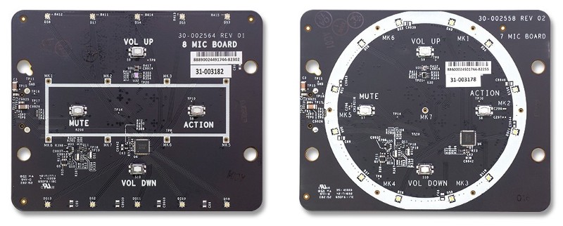
Two microphone array boards
A digital signal processor board
A Raspberry Pi 3 with the Amazon Voice Service (AVS) Device SDK
The 8-microphone board (left) and 7-microphone board (right)
The microphone board comprises of a 7 and 8 microphone arrays optimized for premium far-field audio performance, and the Raspberry PI 3 board can be replaced by any Linux embedded platform for production ready.
The Amazon Alexa Premium Far-Field Voice Development kit is primed for applications that include smart speakers, smart home, IoT devices, router and gateway devices, sound bars, and set-top boxes.
Major Device Technical Specifications:
Microphone Array Configurations –
7 mic circular, 72.76mm diameter
8 mic rectangular, 67.50mm x 22.50mm
Digital Signal Processor –
Intel’s dual DSP with inference engine
System Processor Support –
Raspberry Pi 3 Model B
Compatible with processors capable of running the AVS Device SDK
Power Supply –
15 DC Volt Input
OS Support –
Raspbian Stretch
AVS Device SDK and supports most embedded Linux platforms
With the introduction of the kit, Amazon is lowering the barrier for any company to add Alexa to their products and hopes to make Alexa work everywhere and make it the most important and intimate computer in your life.
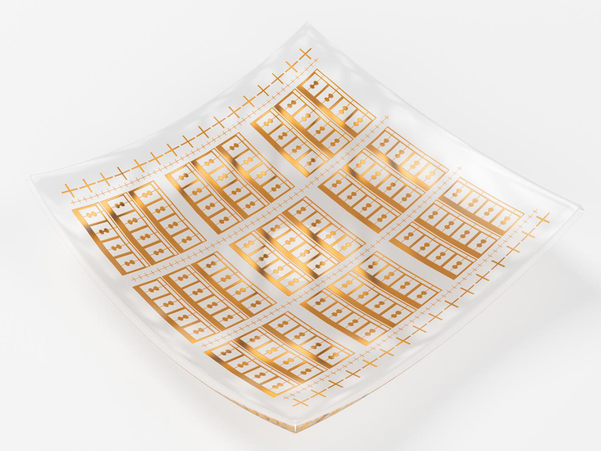
The researchers of the Swedish Chalmers University of Technology have developed a new design of terahertz sensor using Graphene. This flexible sensor can be integrated into wearable materials. Most importantly, it can be manufactured very cheaply and also it is practically transparent. This new type of sensor could be a major breakthrough by opening doors of many new applications.
Flexible Graphene sensor by Chalmers University
The terahertz frequency band ranges from 100 to 10,000 GHz. Terahertz radiation is able to penetrate materials that block visible and mid-infrared light. This technology opened up a range of potential applications in medical diagnostics, process control, and even intelligent vehicles. Jan Stake, the head of the Terahertz and Millimetre Wave Laboratory at Chalmers, said,
Terahertz graphene-based FET detectors have been demonstrated on rigid substrates such as SiO2/Silicon, and flexible devices such as graphene and other concepts have been demonstrated at RF/microwave frequencies.
This band is also used by the so-called “nude-scanners” used at airport check-in desks to look for illegal items carried by passengers. THz waves penetrate normal clothing hence it can detect weapons made of plastic. As Non-metallic weapons cannot be detected by ordinary metal detectors used at the entry gates and by hand-held scanners. Thus these new inexpensive sensors can enhance security for everyone.
Terahertz transmissions have enormous bandwidth available. THz signals can be used as carriers for high-speed information links over short distances allowing data speeds up to 100 Gb/s. On the other hand, THz waves allow uninterrupted visibility in fog or rain for motorized vehicles.
There are many medical applications of the technology using sensors that are cheap to produce and are physically small. One important example is in the field of dermatology. Skin regions affected by cancer have a different reflective index to THz waves which makes the sensor a useful diagnostic tool.
Although being under development for a long time, conventional THz sensors were always large and expensive. With this new design, the Swedish research team has enabled the tech world with mass production of the sensors. New sensors will be small, flexible and cost-effective. Development of the sensors was funded by the European Union under the Graphene Flagship Initiative.
What the Chalmers team has done to combine flexibility and terahertz detection could also make it possible to build an Internet of Things connected via high-bandwidth 5G technologies.
Making solid connections between electrical components on a board is an important part of many hardware projects. A good solder joint forms an alloy at the surface of the PCB and the component lead. During soldering, a solder connection on a circuit board can quickly turn into a real nightmare if not caught immediately, ending up with a too thin or too thick solder joint.
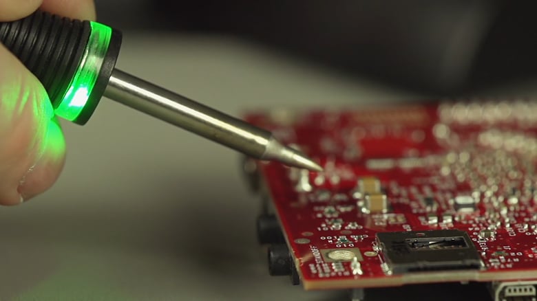
Connection Validation is MetCal’s latest innovation in hand soldering. It allows you to precisely apply the solder to your components. MetCal Connection Validation is to complement or even replace the standard visual inspection during soldering, where now the soldering iron will do it instead.
MetCal Connection Validation (CV) evaluates the quality of the solder joint by calculating the intermetallic compound formation immediately after the soldering iron’s tip is placed on the joint to solder, and it provides closed loop feedback to the operator visually. Connection Validation provides feedback to the operator via the LED light ring integrated into the hand-piece. The Soldering Iron will light up green when the correct intermetallic thickness has formed, and a red light comes on if an error has occurred.
The following are some of the features and benefits of Connection Validation Soldering Station:
Communications Port for process traceability data and firmware graphics
Precise tip temperature display
Integrated Net Power Meter and power graph
Patented Chip-in-Cartridge technology
Closed loop bi-directional communication
Stores and records cartridge attributes
Provides traceability information
Protects power supply from non-conforming cartridges
Backwards compatible with MX series power supplies
Password protection
Introduced at IPC APEX 2017, MetCal’s exciting patent technology was met enthusiastically by contract manufacturers and electronics assembly leaders worldwide.
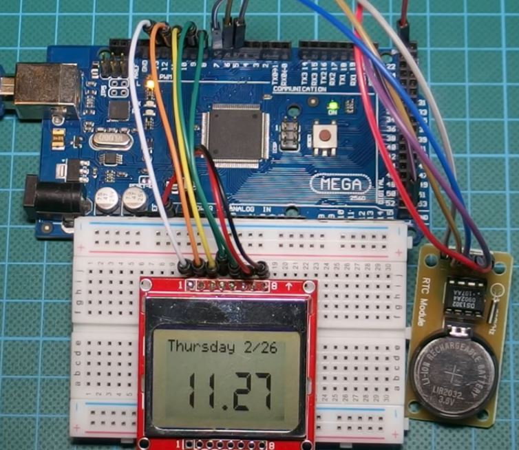
Hi guys, in one of our previous tutorials, we made a real time clock, using the DS3231 RTC Module and the 1602 LCD display module. For this tutorial, we will be building something similar using the DS1302 RTC module and the Nokia 5110 display module. Unlike the 1602 LCD module which was used in the previous tutorial, the Nokia 5110 LCD module has the ability of displaying customized graphics which will help us display our data with better UX.
Arduino Real Time Clock with DS1302 and Nokia 5110 LCD Display – [Link]
Hi guys, in one of our previous tutorials, we made a real time clock, using the DS3231 RTC Module and the 1602 LCD display module. For this tutorial, we will be building something similar using the DS1302 RTC module and the Nokia 5110 display module. Unlike the 1602 LCD module which was used in the previous tutorial, the Nokia 5110 LCD module has the ability to display customized graphics which will help us display our data with better UX.
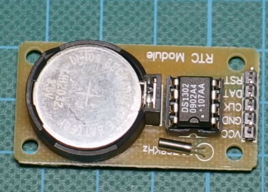
DS1302 Module
At the core of this project is the DS1302 RTC module which is a trickle-charge timekeeping chip which contains a real-time clock/calendar and 31 bytes of static RAM. The real-time clock/calendar provides seconds, minutes, hours, day, date, month, and year information to the micro controller or processor to which its connected via a simple serial interface. The end of the month date is automatically adjusted for months with fewer than 31 days, including corrections for leap year. The device could be set to operate in either the 24-hour or 12-hour format with an AM/PM indicator.
Real Time Clock
Interfacing the DS1302 with a micro controller like the arduino is simplified by using synchronous serial communication. Only three wires are required to communicate with the clock/RAM: reset, data line, and CLK (serial clock). Data can be transferred to and from the clock/RAM 1 byte at a time or in a burst of up to 31 bytes. The DS1302 is designed to operate on very low power and retain data and clock information on less than 1µW.
The module is a successor to the DS1202 RTC module and asides the basic timekeeping functions of the DS1202, the DS1302 has the additional features of dual power pins for primary and backup power supplies, programmable trickle charger for VCC1. This capability makes it ideal for a long term real time clock project.
Required Components
The following components will be needed to build this project;
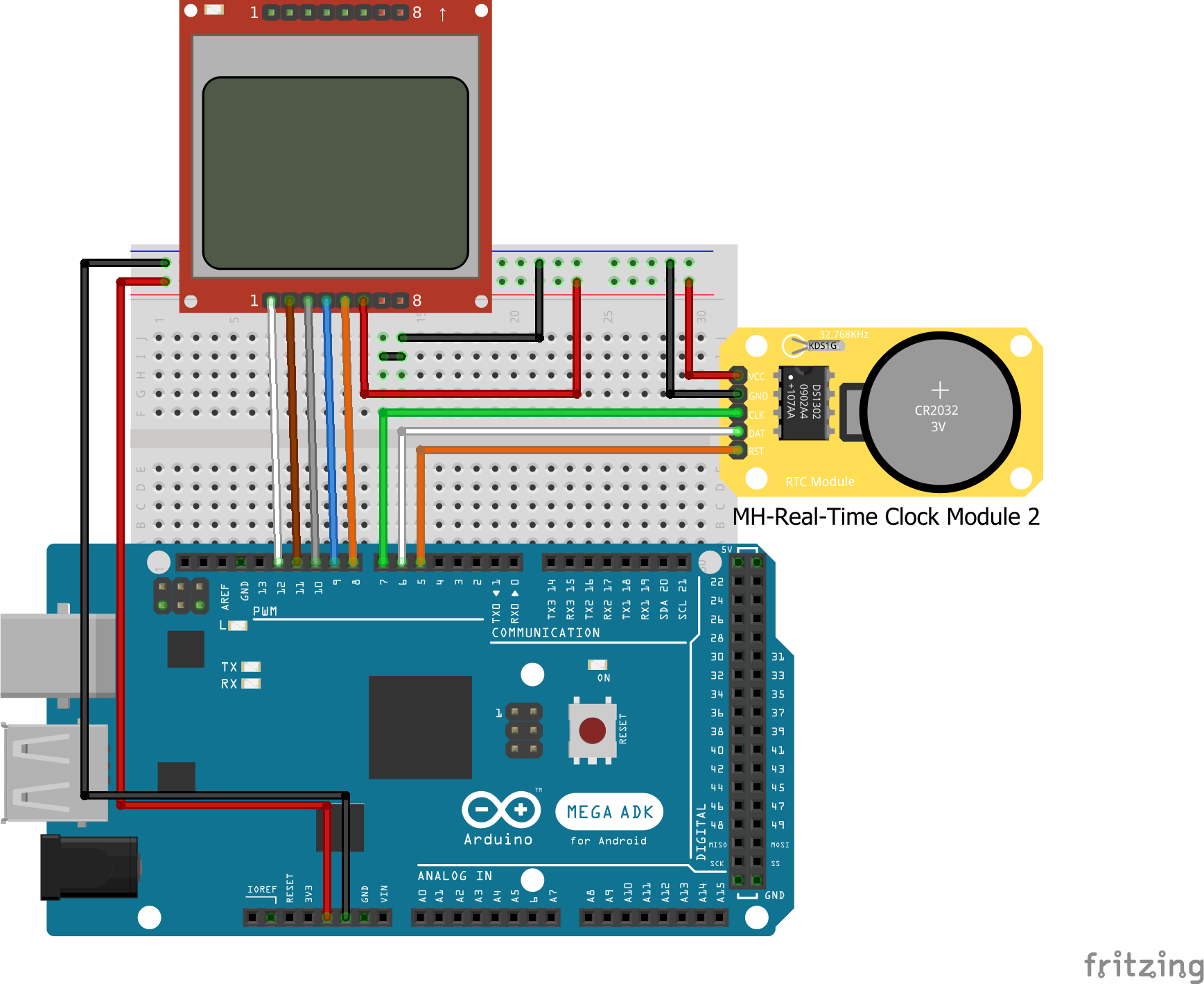
Connect all components as shown in the fritzing schematics below.
Schematics
The DS1302 module has a 3-wire communication interface with which it interacts with the microcontroller. A breakdown of its connection to the Arduino is given below, to make the schematics clearer.
A detailed tutorial has been made before on how to use the nokia 5110 LCD module with the arduino and can be found here. It will help you better understand how the nokia 5110 connection with the arduino works. For this project however, the pin connection of the Nokia 5110 LCD to the Arduino (as shown in the schematics) is given below;
To make writing the code easy for us, the first thing we need to do is to download the msparks ds1302 library from github. After downloading the library, extract it and paste into your arduino libraries folder after which we can launch our arduino IDE to start writing the code.
P.S: for those who have not been following the series of tutorials, its important to note that, to use the Nokia 5110 LCD with the Arduino easily, we need to download the Nokia 5110 LCD library that was made by rinky-dink electronics. The library does most of the heavy lifting and makes it easy for us to write codes to control the LCD. Click here to visit the download page and then download the LCD5110_graph zip file. You can check out this tutorial to know more about using the Nokia 5110 LCD display.
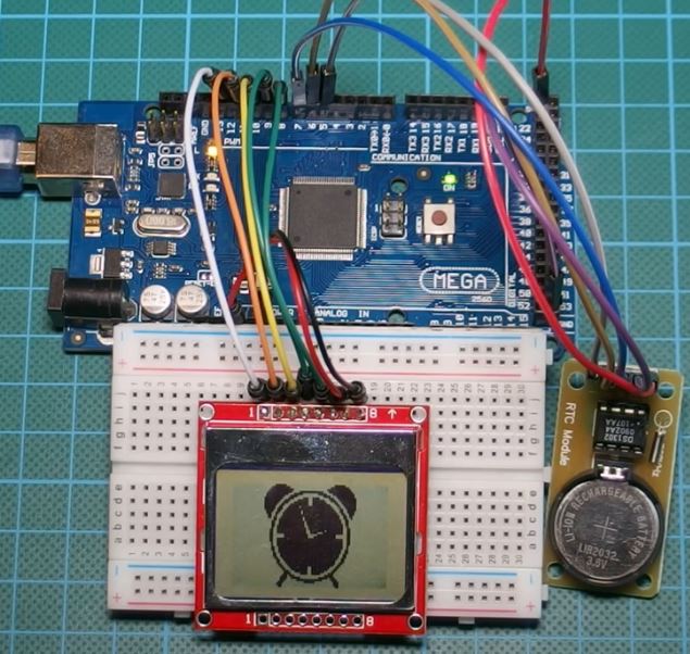
The zip file attached at the bottom of the page contains two files; the code file and the graphics file, which is an hex file for a clock icon. For this project, we will be displaying a clock icon on the LCD asides from the data from the RTC, just to give things a better look. Detailed explanation on how to display your own custom graphics on the Nokia 5110 LCD display was done during on of our previous tutorial here.
As usual, we will do a break down of the code explaining each part, so you can better understand the process.
The first thing we need to do like with every other code, is include all the libraries we will be using.
//Written by Nick Koumaris
// info@educ8s.tv
//educ8s.tv
#include <LCD5110_Graph.h>
#include <stdio.h>
#include <DS1302.h>
Next, we declare the pins to which our LCD is connected and declare the font size along with other parameters for the LCD.
Next, we create a namespace for the RTC. we first declare the pins on the Arduino to which the RTC is connected, and then proceed to create a ds1302 object with the clock, data and reset pin as inputs. Next was setting the cases that returned a particular kind of day.
namespace {
const int kCePin = 5; //RST
const int kIoPin = 6; //DAT
const int kSclkPin = 7; //CLK
// Create a DS1302 object.
DS1302 rtc(kCePin, kIoPin, kSclkPin);
String dayAsString(const Time::Day day) {
switch (day) {
case Time::kSunday: return "Sunday";
case Time::kMonday: return "Monday";
case Time::kTuesday: return "Tuesday";
case Time::kWednesday: return "Wednesday";
case Time::kThursday: return "Thursday";
case Time::kFriday: return "Friday";
case Time::kSaturday: return "Saturday";
}
return "(unknown day)";
}
}
With this done, we then proceed to the setup function. The first thing we do is set the time on our RTC. this command needs to only run once in the lifetime of our project. we will never need to set the time again even when the device goes off for a while because the DS1302 has a battery back up with which it can run for years without losing track of time/date. after the first run, the line of code is commented out and the code uploaded to the microcontroller again.
void setup() {
setTime();
After setting the time, we then initialize the LCD and clear the screen to get it ready to display new data.
lcd.InitLCD();
lcd.clrScr();
Next, we display the clock icon, which can be imported into your code by clicking on sketch on the IDE and selecting add file. Navigate to where the file is and add to your code. After drawing the Icon and issueing the update command to the LCD to display it, we then insert a delay of some seconds to give the icon enough to time to show on the screen.
with the setup all done. we are ready to move to the loop function.
The loop function contains just two lines of code as emphasis was on making the code as modular as possible. the first line of code is the printtime() function which handles printing the current date and time on the LCD. the second is a delay function which ensure the data being displayed stays on the screen long enough to be seen.
void loop() {
printTime();
delay(1000);
}
Next we move to the printtime() function which actually handles the display of time from the rtc on the LCD. the first line gets the time and calendar information from the rtc and stores in the variable “t” which is of type “time”. After this is done, we then declare the names of the variables that will hold both time and calendar information, from month to date.
void printTime() {
Time t = rtc.time();
const String day = dayAsString(t.day);
String month;
String date;
String hour;
String minutes;
month = String(t.mon);
date = String(t.date);
hour = String(t.hr);
minutes = String(t.min);
String fullDate = day+" "+month+"/"+date;
Next, the screen is cleared, font selected and the time and date are displayed.
The last function (Void Settime()) is for setting the time as the ds1302 module does not come with the clock, correct.
To set the time, the first thing we need to do is turn off write protection for the ds1302 rtc module, so we can address it’s registers. Next, we start the operation of the rtc using the rtc.halt(false) command. With this done the device is ready to receive data, so we input the current time and date with kthursday if its a Thursday or kmonday, if it’s a Monday.
void setTime()
{
rtc.writeProtect(false);
rtc.halt(false);
Time t(2015, 2, 26, 13, 35, 50, Time::kThursday); //Change this line to set time ex 2015 26/2 9:09:50
rtc.time(t);
}
Go over the code and be sure everything is at it should be, then upload to your Arduino board.
The Full code for the project is available below and attached in the zip file at the end of this post along with the hex file for the clock Icon.
//Written by Nick Koumaris
// info@educ8s.tv
//educ8s.tv
#include <LCD5110_Graph.h>
#include <stdio.h>
#include <DS1302.h>
LCD5110 lcd(8,9,10,12,11);
extern unsigned char BigNumbers[];
extern unsigned char SmallFont[];
extern uint8_t clock[];
namespace {

const int kCePin   = 5;  //RST
const int kIoPin   = 6;  //DAT
const int kSclkPin = 7;  //CLK

// Create a DS1302 object.
DS1302 rtc(kCePin, kIoPin, kSclkPin);

String dayAsString(const Time::Day day) {
  switch (day) {
    case Time::kSunday: return "Sunday";
    case Time::kMonday: return "Monday";
    case Time::kTuesday: return "Tuesday";
    case Time::kWednesday: return "Wednesday";
    case Time::kThursday: return "Thursday";
    case Time::kFriday: return "Friday";
    case Time::kSaturday: return "Saturday";
  }
  return "(unknown day)";
}
}
void setup() {

 setTime();
lcd.InitLCD();
 lcd.clrScr();
lcd.drawBitmap(0, 0, clock, 84, 48);
lcd.update();
delay(3000);
}
void loop() {

 printTime();
 delay(1000);
}
void printTime() {

  Time t = rtc.time();

  const String day = dayAsString(t.day);
  String month;
  String date;
  String hour;
  String minutes;

  month = String(t.mon);
  date = String(t.date);
  hour = String(t.hr);
  minutes = String(t.min);

 String fullDate = day+" "+month+"/"+date;
lcd.clrScr();
  lcd.setFont(SmallFont);
  lcd.print(fullDate,0,0);

  lcd.setFont(BigNumbers);

  if(t.hr<10)
  {
    hour = "0"+hour;
    lcd.print(hour,7,18);
  }else
  {
        lcd.print(hour,7,18);
  }
  lcd.print(".",35,18);
  if(t.min<10)
  {
    minutes = "0"+minutes;
    lcd.print(minutes,47,18);
  }else
  {
      lcd.print(minutes,47,18);
  }
  lcd.update();
}
void setTime()
{
  rtc.writeProtect(false);
  rtc.halt(false);
  Time t(2015, 2, 26, 13, 35, 50, Time::kThursday); //Change this line to set time  ex 2015 26/2 9:09:50
  rtc.time(t);
}
Demo
Copy the code, paste in the Arduino IDE, and upload to your arduino board, you should get an output like the image below on your screen. Don’t forget to include the icon file in the Arduino sketch folder.
Demo
That’s it for this tutorial guys. As usual, let me know if you have any questions via the comments section.
The youtube video of this tutorial is available here.
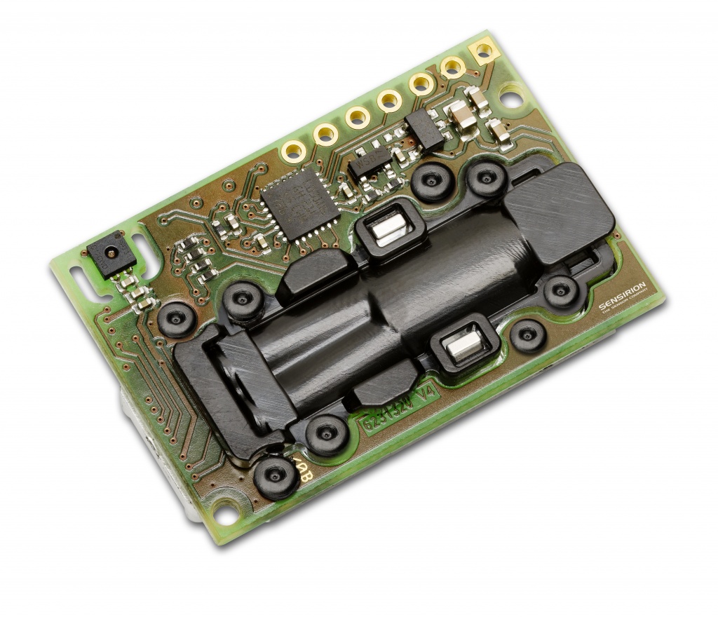
At this year’s AHR Expo 2018 trade show in Chicago (January 22 – 24, 2018), Sensirion, the expert in environmental and flow sensor solutions, is introducing the SCD30 – a humidity, temperature and carbon dioxide concentration sensor.
CMOSens® Technology for IR detection enables highly accurate carbon dioxide measurement at a competitive price. Along with the NDIR measurement technology for CO2 detection, a best-in-class Sensirion humidity and temperature sensor is also integrated on the same sensor module. Ambient humidity and temperature can be outputted by Sensirion’s algorithm expertise through modeling and compensating of external heat sources without the requirement for any additional components. Thanks to the dual-channel principle for the measurement of carbon dioxide concentration, the sensor compensates for long-term drifts automatically by design. The very small module height allows easy integration into different applications.
Carbon dioxide is a key indicator of indoor air quality. Thanks to new energy standards and better insulation, houses have become increasingly energy efficient, but the air quality can deteriorate rapidly. Active ventilation is needed to maintain a comfortable and healthy indoor environment, and to improve the well-being and productivity of the inhabitants. Sensirion’s SCD30 offers accurate and stable CO2, temperature and humidity monitoring. This enables customers to develop new solutions that increase energy efficiency and simultaneously support well-being. With the new SCD30, Sensirion has expanded its portfolio to include environmental sensor for air quality measurement.
Visit Sensirion at AHR Expo 2018 (Booth 3858) and learn more about the SCD30, Sensirion’s new humidity, temperature and carbon dioxide sensor module.
Recently, I had the opportunity to test the printed circuit boards (PCB) offered by JLCPCB. These tests were made in two different boards of the brand and here I’ll report my impressions about them.
Due to the spread of the maker culture and the do-it-yourself (DIY) and easy access to components and a huge amount of technical information available on Internet, it has become much simpler to develop a solution to a problem or just have fun soldering some components.
However, taking the design out of a breadboard (or universal board) and turning it into a PCB stills a big challenge, mainly due to the costs involved.
And exactly at this point the services offered by JLCPCB make the difference, offering a high level service of PCB manufacturing with an extremely competitive cost.
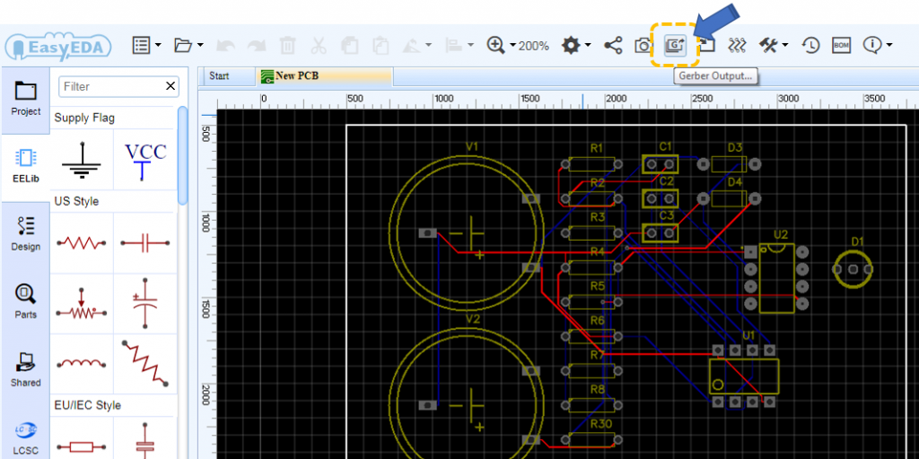
Requesting the production of PCBs is quite simple and there are two basic ways to do it. If you are developing within EasyEDA just click on “Gerber Output” and your gerber file will be generated and transferred directly to the JLCPCB system.