A team of researchers from Tsinghua University in cooperation with People’s Liberation Army Air Force General Hospital, China, has produced a two-stage patch to test the blood glucose levels. They published their research paper on the open access site Science Advances. In the paper, the group describes their patch system and how it succeeds in a small sample test with volunteer human patients.
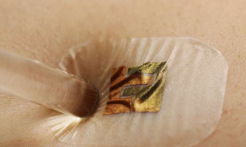
Biosensor attached to the skin for measuring blood glucose level
In this new effort, the researchers of Tsinghua University sought to make life a little easier for people living with diabetes by developing an easier way to test their glucose levels. Now they can easily monitor their own blood glucose level and maintain their diet accordingly.
For most diabetics, the conventional method was to check their glucose levels by using a small device that pricks the skin just enough to draw a very tiny amount of blood, usually from a fingertip. A drop of blood is then squeezed onto a test strip inserted into a glucose monitoring device, which then shows a reading. This painful and prone to infection process often causes many diabetics to stop testing their blood glucose level, hence putting themselves at higher risk.
Schematic diagram of non-invasive blood glucose monitoring
In this new procedure, the researchers introduced a two-stage, non-invasive method to accomplish the same result. The first stage consists of placing a small amount of Hyaluronic acid, a component frequently found in skincare products, on the skin and then pressing a paper battery on the same area. The battery pushes the acid to make its way into the skin. Then the acid induces a change in osmotic pressure in the subcutaneous fluid. That forces glucose back upwards toward the outer surface of the skin. After 20 minutes, the battery is removed and the second stage takes place. A 3μm thick, five-layer biosensor is attached to the same place of the skin. It looks like a Band-Aid with a square of gold foil on its center. The biosensor can be read by standard lab equipment.
A clinical trial of their device on a woman with diabetes and two other non-diabetic patients at the hospital showed that results were nearly as good as standard lab equipment without causing any discomfort to the volunteers. In the following video, the researchers explain how it works:
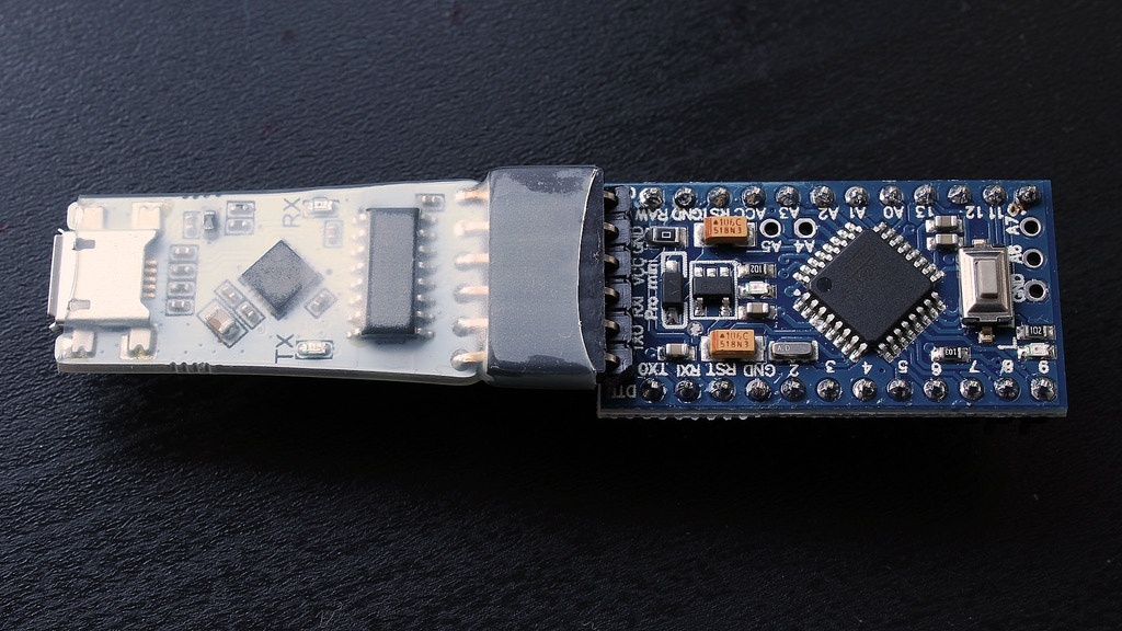
Simple, tiny USB to UART converter with digital isolator working between 2.5V and 5V up to 3Mbaud, with the Arduino Pro mini connector.
It’s a USB to UART converter with a digital isolator at the UART side. It has a micro USB for connecting to the PC and a 6 pin header with the same pin-out of the Arduino Pro mini board.
The chip FT231XQ is used as interface between the USB and the UART protocol, while the Si8642 is used for isolate the board from the PC. This converter is very useful if you are working on some projects and worrying about short circuit with the main power supply. Because the isolator isolates the two sides therefore there is no electrically connection.
Specifications
Original FT231XQ: Compatible with almost all the operating systems and capable of variety baud rates from 300 baud up to 3 Mbaud
Original Si8642BB-B-IS1: Low-Power Quad-Channel Digital Isolators with isolation rating up to 2.5kV
Size of 40 x 17 mm
4.1 mm isolation between the two sides guarantee an electrical isolation up to 1kV
Working between 2.5V to 5V.
TX and RX LEDs indicators.
Micro USB connector.
Standard 2.54mm 6 pins female header.
Protected by a transparent heat shrink sleeve.
The board is live on kickstarter available for funding and has 24 days to go.
Hi guys, for today’s tutorial, we will be building an Arduino on a breadboard. The Arduino on breadboard is basically a bare bones arduino, featuring only the micro-controller as the major component, without all the other parts that makes up the Arduino, like the usb port, the on-board serial to usb converter, voltage regulators, etc, most of which are sometimes not needed in a project after programming has been done.
Hi guys, for today’s tutorial, we will be building an Arduino on a breadboard. The Arduino on breadboard is basically a bare bones arduino, featuring only the micro-controller as the major component, without all the other parts that makes up the Arduino, like the USB port, the on-board serial to usb converter, voltage regulators, etc, most of which are sometimes not needed in a project after programming has been done.
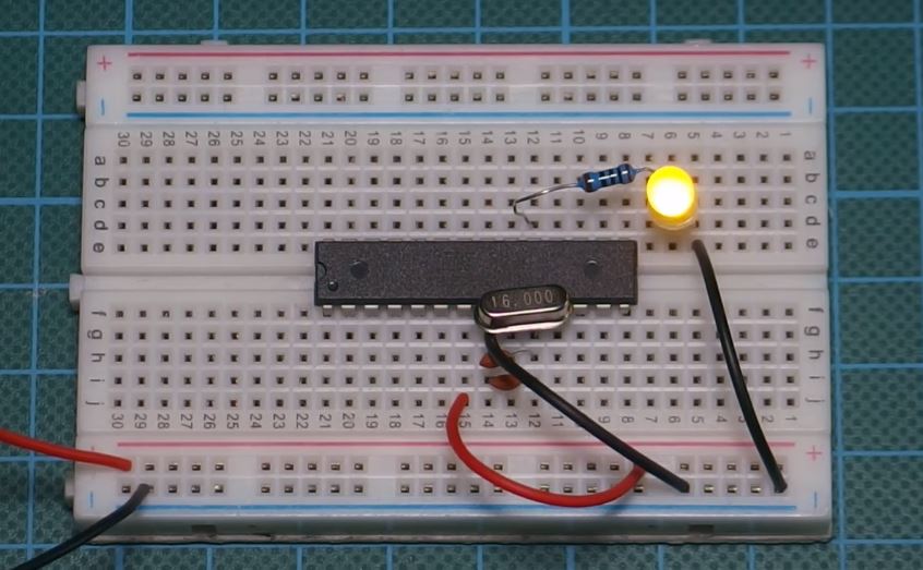
Arduino on Breadboard
While they look similar, the difference between the ordinary atmeg328p microcontroller based circuit and the arduino on breadboard is the fact that, the microcontroller used for the Arduino on breadboard always carries the arduino bootloader which allows it to be programmed using the arduino IDE. This is not the case with the ordinary atmeg328p microcontroller system as the microcontroller can’t be programmed using the Arduino IDE.
This project is very easy and shouldn’t take a lot of time to implement, but before we proceed to the tutorial, its important to explore some of the benefits and reasons for this project, especially when we could get a cheap “alternative” in the Arduino pro mini for less than $2, if size was the only benefit.
Some benefits of the Arduino on Breadboard are listed below with the most important one for me being the second one as optimizing power for devices is very important in design.
Working with the Atmega328p on a breadboard will give a deeper understanding of how the Arduino hardware works.
The second benefit is the low power consumption of this project, compared to all other types of Arduino including the pro mini, this consumes far less amount of power in standby mode. Reason for this is obviously the removal of all the other peripherals that comes with other arduino board.
Its easier to scale an electronic prototype implemented using the arduino on breadboard as you are privy to every detail.
Components Required
The following components will be needed to build this project;
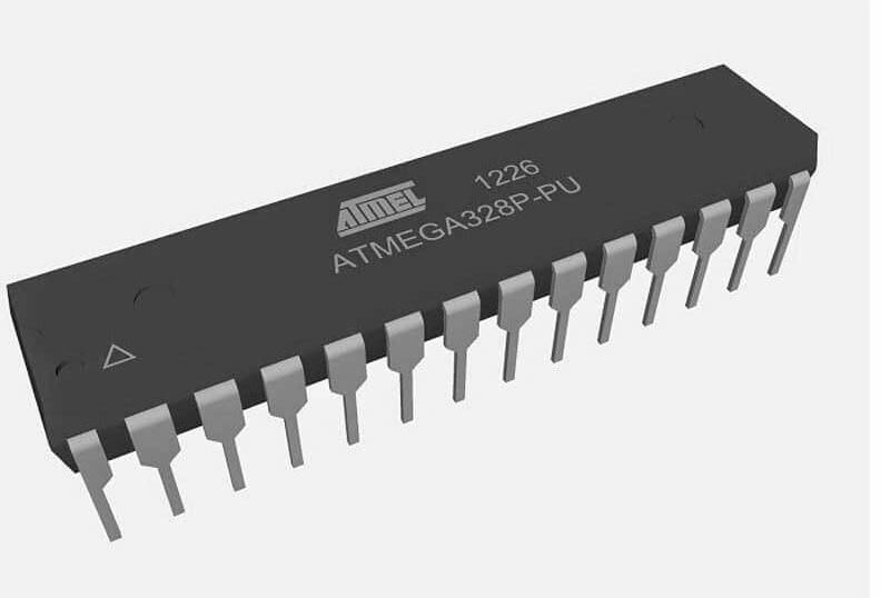
While buying the atmega328p, its important to ensure that the one being bought, has the Arduino bootloader on it as this procedure will not work for the atmega chip without the Arduino bootloader.
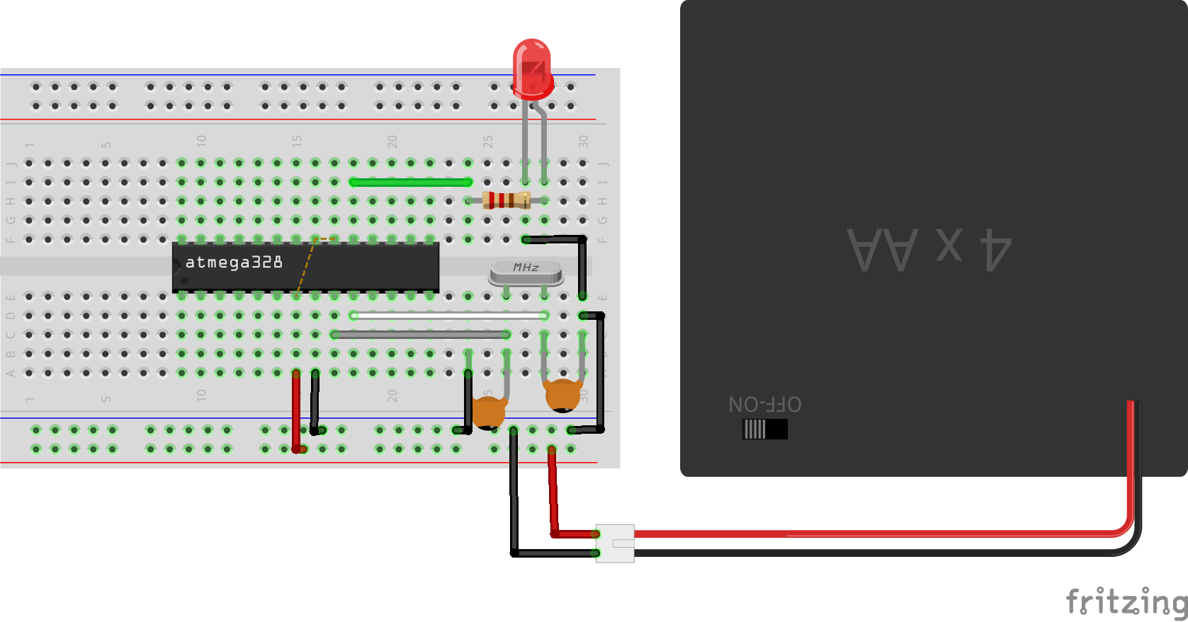
Schematics
Connect the components of the Arduino on breadboard as shown in the schematic below.
Schematics
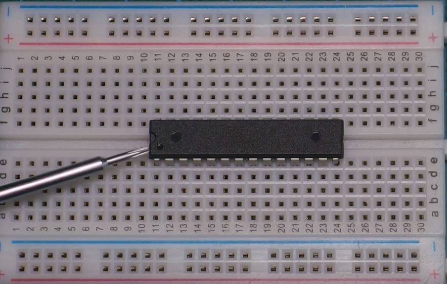
To make it easy to connect the components to the microcontroller, A sticker which translates the pins of the microcontroller to the equivalent pin on the Arduino is pasted on top of the microcontroller. This sticker is included in the zip file attached at the end of this tutorial and can be used to make the connections easy for you.
Sticker placed for easy connection
While plugging the microcontroller to the breadboard, take note of the notch at the top left which signifies the first pin (RST) of the microcontroller. Numbering of the microcontroller’s pin should start from there to prevent connecting the components wrongly.
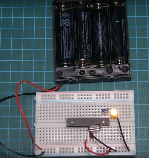
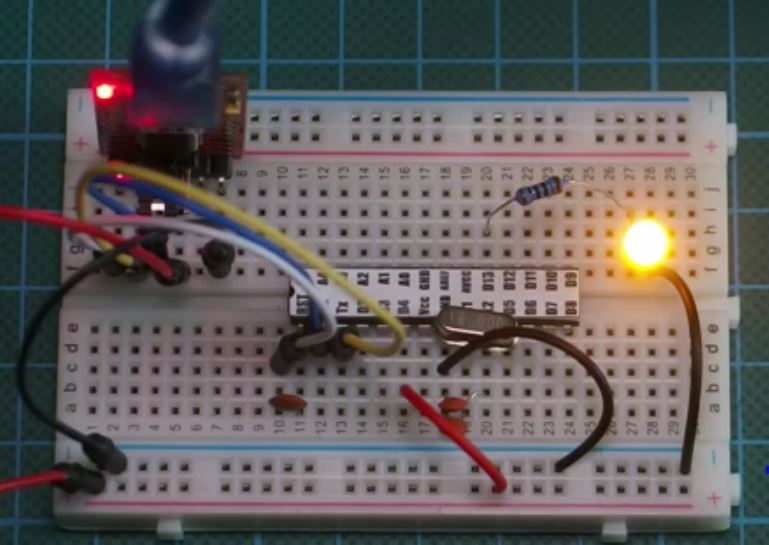
With the circuit and power connected, you should see the led start blinking.
Notch which Marks pin 1
It should be noted that the maximum voltage which should be applied to the VCC pin of the atmeg328p microcontroller is 6v and this should be avoided, as the advisable working voltage is between 3.3V and 5.5V.
Programming the Breadboard Arduino
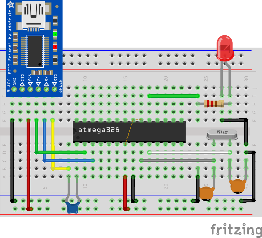
Once the component setup is done, the next thing is programming the arduino on breadboard to run our desired code/firmware. The flashing of the LED that we saw from the last section after the setup was powered was due to the blink led code that comes with the Arduino bootloader. To program the Arduino on breadboard and flash it with your own code, we will need to connect the USB to Serial Converter module to the Arduino on breadboard.
USB to serial adapters generally connect a serial device to the computer via USB ports. It gives the Arduino IDE the communication path needed to flash the microcontroller with the written Arduino code. On boards like the Arduino UNO, the communication between the microcontroller and the USB port is achieved by the actions of the ATMEGA8u2 chip which behaves as the bridge between the USB port and the microcontroller on the board.
Connect the USB to serial converter module to the Arduino on breadboard circuit as shown in the image below.
With the connection all done, connect the setup to your computer and open the Arduino IDE.
To upload code to the Arduino on breadboard, after writing your code (For the purpose of this tutorial, we are modifying the blink example), go to the tools section and select board type. For the arduino on breadboard, the matching board type is “Arduino Duemilanove or Nano w/ ATmega328“, select this alongside the matching com port and you are ready to upload to the microcontroller as normal.
Code
This section exists just in case you are interested in our code. As mentioned earlier, its a modified version of the Arduino blink program but features the Lowpower.h Arduino library.
The arduino low power library is a lightweight power management library for the arduino which allows the arduino peripherals like the ADC etc be turned off to conserve power. The library has different functions with different operation modes and may be worth exploring. it can be downloaded from here.
The first thing we do in the code imports the low power library which allows us to do everything that has been said about it in the previous paragraph, after which we proceed to the void setup where we do just one thing; set the pin 13 as an output.
//written by Nick Koumaris
//info@educ8s.tv
//educ8s.tv

#include "LowPower.h"

void setup()
{
  pinMode(13, OUTPUT);
}
Next is the void loop where the real action happens, we instruct the microcontroller via the lowpower.powerdown() command to go into sleep mode, for 8s, turning off the ADC and other peripherals.
void loop()
{
    // Enter power down state for 8 s with ADC and BOD module disabled
    LowPower.powerDown(SLEEP_8S, ADC_OFF, BOD_OFF);
As soon as the microcontroller wakes up from the sleep, it then writes pin 13 high, for 1s and then turn it back low.
digitalWrite(13, HIGH);   // turn the LED on (HIGH is the voltage level)
  delay(1000);              // wait for a second
  digitalWrite(13, LOW);    // turn the LED off by making the voltage LOW
  delay(1000);
The full code is available below and in the zip file attached at the end of the post.
// **** INCLUDES *****
#include "LowPower.h"

void setup()
{
  pinMode(13, OUTPUT);
}

void loop()
{
    // Enter power down state for 8 s with ADC and BOD module disabled
    LowPower.powerDown(SLEEP_8S, ADC_OFF, BOD_OFF);

  digitalWrite(13, HIGH);   // turn the LED on (HIGH is the voltage level)
  delay(1000);              // wait for a second
  digitalWrite(13, LOW);    // turn the LED off by making the voltage LOW
  delay(1000);
}
After uploading to your Arduino on a breadboard, you should see the LED come on for one second and go off for the next 8s.
Works right? Yea, here is a picture of ours too working.
Demo
So now you can proceed and build several other cool projects using the Arduino on breadboard.
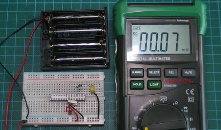
As a proof of the low power consumption rate of the microcontroller when in idle mode, we used the maestech meter to measure the current consumption and got 0.07mA in idle mode. This is far less than any of the Arduino boards with Arduino pro mini consuming around 3mA and Uno, 30mA in Idle Mode. This shows that you can have an Arduino project like a weather station for example, that could last for years running on batteries and this increases the potential of what you can do with the Arduino platform drastically.
That’s it for this tutorial guys, don’t forget to leave questions, and comments, in the comments section of the tutorial.
Till next time, Keep Building!
The youtube video for this tutorial is available via the attached link, here.
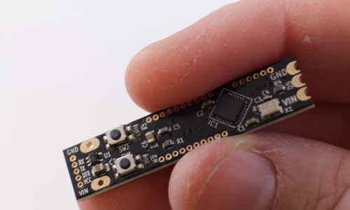
FPGAs are field programmable gate arrays which basically means they are reconfigurable hardware chips. FPGAs have found applications in different industries and engineering fields from the defence, telecommunications to automotive and several others but little application in the maker’s world. Mostly, as a result of being largely difficult and high cost as compared to the likes of Arduino, but the introduction of the ezPixel and other similar FPGA boards is making this a possibility.
Prototype modules.
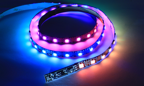
The ezPixel board, by Thomas Burke of MakerLogic, is a small size FPGA based circuit board that can be used to drive up to 32 strings of WS2812Bs, for up to 9,216 LEDs in total, a very first of its kind. These WS2812B programmable color LEDs have been a phenomenon in the maker’s world, being used in various Led Lights and creating of various Light Artworks. These popular LEDs comes in strings that can be cut to any length, and only require a single wire serial data connection to control all the lights in the string individually, and multiple strings can be stacked together to create large two-dimensional displays.
ezPixel description.
Most WS2812B controller boards can be used to control up to hundreds of these LEDs, but not thousands of them. The ezPixel board is a perfect fit for applications that use thousands of these LEDs. The ezPixel board is powered by the Intel MAX FPGA, a single chip small form factor programmable logic device with full-featured FPGA capabilities, and it’s designed to interface with other Micro-controllers or any SPI/UART host device. The ezPixel board serves as bridge between microcontrollers and long WS2812B strings. A user sets the length of each string using simple commands that are sent via the SPI or USB/UART communication link.
The following below are the features of the ezPixel:
WS2812B Smart Pixel Controller.
Up to 32 Strings can be controlled independently.
Up to 9216 LEDs can be controlled.
Communication:
USB/UART Interface.
SPI Interface.
Read/Write Pixel Memory.
FPGA – Intel MAX10M08 FPGA.
Dimension:
1” x 3” (25mm x 76mm).
SPI Flash.
The ezPixel can run as a standalone display controller as a result of its serial flash memory chip, and this board is slated for a crowdfunding campaign in early 2018.
LED strips provide users with multi-color and flexible illumination which can be fit into tight spacing. Also, they are customizable, durable, and easy to install which is why LED strips have gained popularity in design and personal projects. However, installing them can result in a lot of wire, power transistors (to control the LEDs), a microcontroller, a voltage regulator, and a lot of soldering. When danjhamer, a user from Hackaday, faced this problem while doing a small project with his daughter he came up with ChromaTab.
ChromaTab is a small control board for WS2812B RGB LED strips that can be soldered directly into the end of the strip. The device has 14 digital pins, 6 analog pins, and Arduino compatibility which allows the users to update and upload new sketches using the Arduino IDE. The sketches are to be uploaded though a USB to serial converter and as the firmware is based on Adafruit Neopixel library, effects and animations can be easily created.
It has an input voltage of 5-7 v, a current of 90 mA, clock speed of 16 MHz, SRAM of 2 KB and flash memory of 32 KB. It’s based-on Arduino Pro mini and Atmega 328P microcontroller. It is 43 mm wide, 10 mm High and 4 mm deep this size makes it easy to fit in small places. The only soldering needed is the 3 castellated pads to solder directly into the LED strip making your project more simple, organized, and easier to program. The complete specifications can be found on its official Hackaday website.
The ChromaTab could be perfect for kids learning about electronics or designers who want to use LED strips but don´t know much about electronics. Its already on sale in this website for € 18,00. Soon there will be add-on boards on sale to provide extra functions such as USB to serial converter. The device is cheap and offers to facilitate an otherwise boring task, but some improvements could be made such as making it water resistant (for Waterproof LED strips) or making it adaptable to other LED strip references. ChromaTab opens the door to a lot of projects and possibilities which is why it needs to keep improving to adapt to user’s project needs.
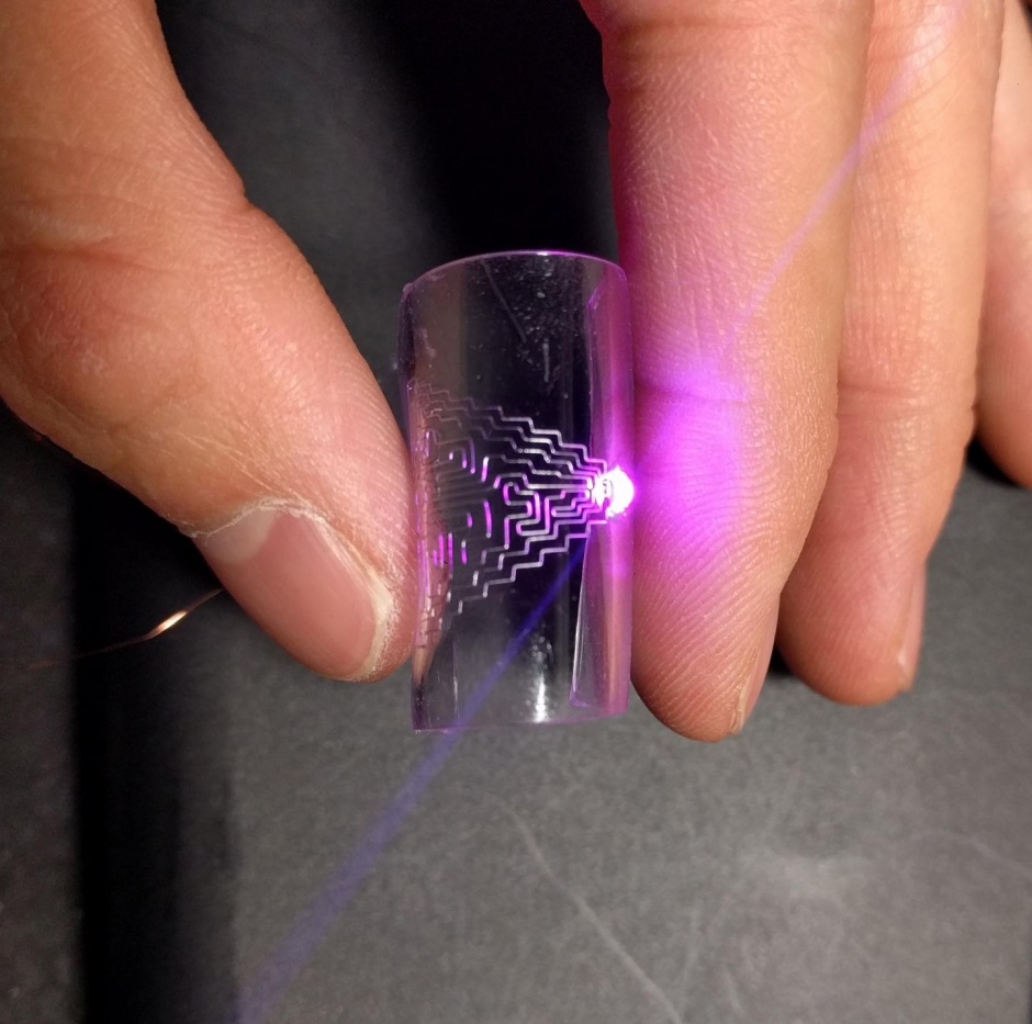
The researchers of North Carolina StateUniversity in the US, lead by Jingyan Dong, have developed a new technique for directly printing flexible, stretchable metal circuits. The innovative technique can be used with multiple metals and alloys. It is also compatible with existing manufacturing systems which can integrate this new printing technology effortlessly.
Flexible PCB designed by the researchers
The technique uses the well known electrohydrodynamic printing technology. This popular technology is already used in many manufacturing processes that use functional inks. But instead of using conventional functional ink, Jingyan Dong’s team uses molten alloys having melting point as low as 60 degrees Celsius. This new technique was demonstrated using three different alloys, printing on different substrates such as glass, paper, and two types of stretchable polymers. Jingyan Dong added,
Our approach should reduce cost and offer an efficient means of producing circuits with high resolution, making them viable for integrating into commercial devices.
The researchers tested the flexibility of the circuits on a polymer substrate and found that the circuit’s conductivity was uninterrupted even after being flexed 1,000 times. The circuits were still electrically firm even when stretched to 70 percent of tensile strain. The above figures are surprising enough, especially when printing flexible wearables is the main target.
Even more interesting, the circuits can heal themselves if they are broken by being bent or stretched beyond their limitations. On the other hand, because of the low melting point, one can simply heat the affected area up to around 70 degrees Celsius and make the metal flow back together, repairing the related damage with ease.
The researchers demonstrated the functionality of the printing technique by creating a high-density touch sensor, packing a 400-pixel assemblage into one square centimeter. The researchers have demonstrated the flexibility and functionality of their approach. Now, they are planning to work with the industry sector to implement the technique in manufacturing wearable sensors or other electronic devices.
The days of truly flexible, self-healing wearable smart gadgets are not so far because of the hard work of these researchers.
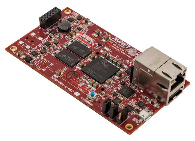
MicroZed is a low-cost development board from Avnet, the makers of the $475 ZedBoard and the entry level MiniZed development boards. Its unique design allows it to be used as both a stand-alone evaluation board for basic SoC experimentation or combined with a carrier card as an embeddable system-on-module (SOM).
The MicroZed processing system is based on the Xilinx Zynq®-7000 All Programmable SoC. The Zynq®-7000 All Programmable SoC (AP SoC) family integrates the software programmability of an ARM®-based processor with the hardware programmability of an FPGA, enabling key analytics and hardware acceleration while integrating CPU, DSP, ASSP, and mixed-signal functionality on a single device. The processing system offers the ability to run standard operating systems like Linux, real-time operating systems, or a combination of the two. The programmable logic provides a unique capability to create custom interfaces or custom accelerators. Together, they provide a versatile, performance optimized solution.
ZedBoard™ is a low-cost development board for the Xilinx Zynq®-7000 All Programmable SoC. This board contains everything necessary to create a Linux, Android, Windows® or other OS/RTOS-based design all at a cost of $495. The MicroZed sells for $199 with close performance and functionality with the ZedBoard. MicroZed contains two I/O headers that provide connection to two I/O banks on the programmable logic (PL) side of the Zynq – 7000 AP SoC device. In stand-alone mode, these 100 PL I/O are inactive. When plugged into a carrier card, the I/O are accessible in a manner defined by the carrier card design. The MicroZed board targets application in the areas of general FPGA evaluation and prototyping, embedded SOM applications, embedded vision, test & measurement, motor control, software-defined radio, industrial network and industrial IoT.
The Zedboard is based on Zynq-7020 with 85K logic cells while the MicroZed is based on the lower Zynq-7010 with a 28K logic cell. The MicroZed has 1GB RAM instead of 512 MB on the ZedBoard and has lesser interfaces as compared to the ZedBoard.
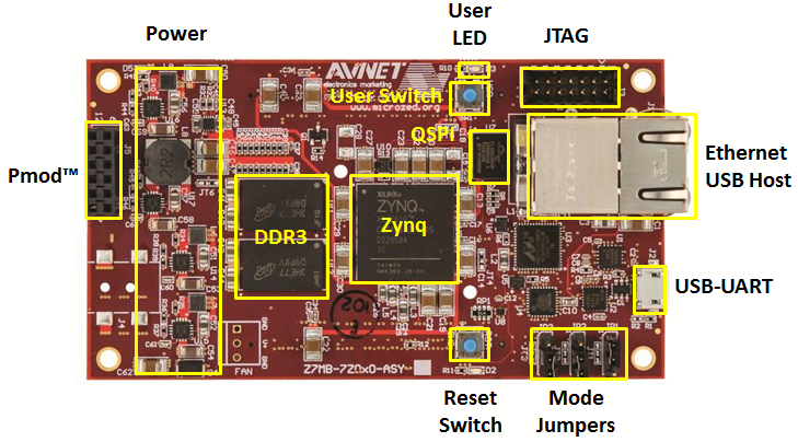
The following below are the features of the MicroZed SoM:
SoC
XC7Z010 – 1CLG400C
Memory
1 GB of DDR3 SDRAM
128 Mb of QSPI Flash
Micro SD card interface
Communications
10/100/1000 Ethernet
USB 2.0
USB-UART
User I/0 (via dual board-to-board connectors)
7Z010 Version
100 User I/0 (50 per connector)
Configurable as up to 48 LVDS pairs or 100 single-ended I/O
Misc
2×6 Digilent Pmod compatible interface providing 8 PS MIO connections for user I/0
Xilinx PC4 JTAG configuration port
PS JTAG pins accessible via Pmod
33Mhz oscillator
User LED and push switch
The MicroZed Evaluation can be purchased from the Avnet store here and comes with the following: MicroZed board, Micro USB cable, 4GB μSD card, Getting Started Card and a Xilinx Vivado WebPACK support and the Avnet’s MicroZed SOM comes bundled with the Wind River’s Pulsar™ Linux.
The increasing popularity of unmanned aerial vehicles (drones) has created a lot of security issues and possible privacy threats. Drone manufacturers have made them easy to fly so that any person without any experience can buy one and fly it without reading the instruction manual first. This has made them attractive for consumers, but also for criminals. Most of them have a camera to allow the user to go to distances beyond their sight. As a result, drones are now being used by many companies to make deliveries such as Amazon, by people to take selfies, by explorers, by authorities etc. This increased amount of usage may pose security threats to privacy and commercial space.
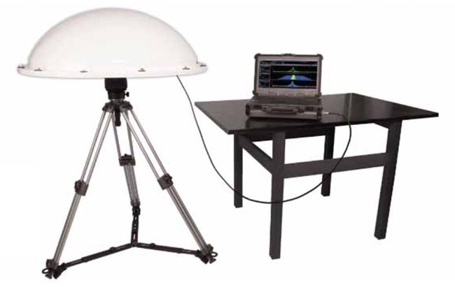
For example, there is already reported cases of drones almost crashing into military aircrafts, or invading the helicopters flying area when trying to put out a forest fire, hacked drones, or drones being used to smuggle drugs. Additionally, there are a lot of reports involving drones constantly flying over private properties while recording. Drones are difficult to detect because of their size, so the company Aaronia produced a new drone detection system that tracks the high-frequency signal between these devices and it´s remote control.
The device consists of a IsoLOG 3D antenna, a Spectran V5 spectrum analyzer and a plug in for the RTSA software. It offers the user a long detection range, functionality in poor visibility, high resolution of signal detection, portability, drone identification etc.
This system provides detailed information of signal distribution, and can be combined with different devices to provide a bigger range of detection. It can be programmed to set off an alarm when some selected parameters are exceeded. The IsoLOG 3D has 16 sectors that provide full 360 RF spectrum overview including an image of the monitored area. It has W signal sensitivity and continuous data streaming with up to 4 TB per day.
Militaries could use this device to protect large areas, and even in the future to stop the drones from entering areas where they could interfere with life threatening situations or confidentiality sensitive scenarios. For now, only detection is possible, but it is a huge step toward fixing the security concern posed by drones. Some parts in the United States have already implemented laws to register all drones and to prohibit the users from flying them above certain heights and close to airports. These governmental measures can help the Aaronia device to easily identify the drones, and the device could help the authorities to stop people from breaking the law.
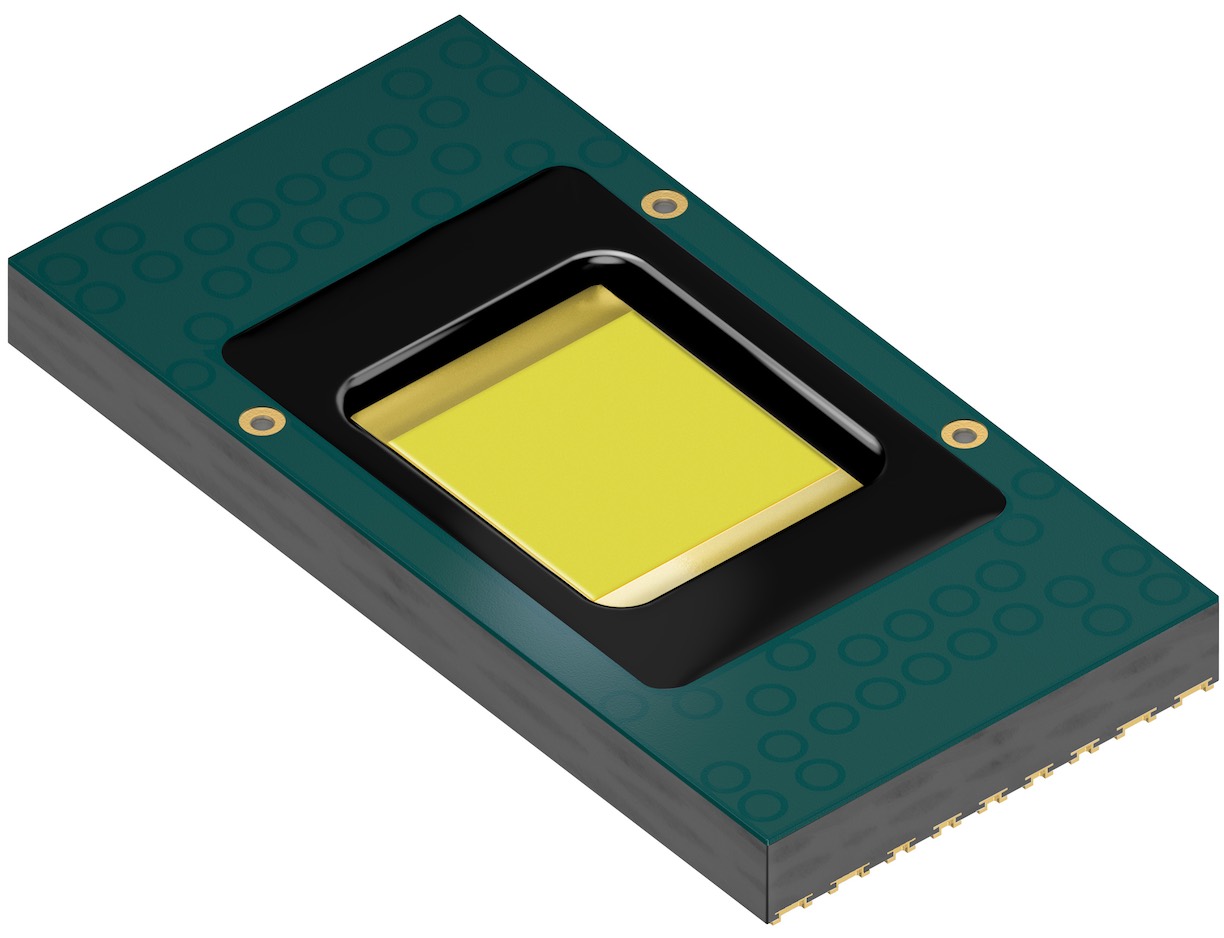
After over three years of research and field demos, a prototype of Osram’s EVIYOS smart, controllable, high resolution LED automotive headlamp was introduced at the International Symposium on Automotive Lighting earlier this year in Darmstadt, Germany. This smart LED headlamp is able to control its 1,024 LED “pixels” individually. The basic component of the EVIYOS combines an LED chip with electronics to provide on/off and dimming control for each pixel within the LED module.
Smart beam array LED headlamp by Osram
The only 4×4 mm module is capable of delivering about 3,000 lumens when fully activated. The brightness is much greater than the 1,400 lumens of the typical LED automotive headlamp modules. The required circuits to control this module is already connected to the headlamp and it includes an interface for connecting directly to the vehicle electronics. The truly “smart” aspect of this invention is, the system can continuously analyze factors such as the car velocity, road curvature, and distance from other vehicles on the road, including oncoming traffic. Then it makes adjustments to the light emitted from the vehicle’s headlamps accordingly.
For instance, a wider beam would be provided for high crowding areas to illuminate the road ahead and also the sidewalks. Having individual pixel control capability, the headlamp can adjust the light output very precisely. Hence, it can provide better visibility for other drivers sharing the road by dimming the specific pixels that would otherwise be causing glare, while still illuminating the road nicely.
As it is scheduled to launch in 2020, Osram is looking forward to offering a separate family of modules targeting lighting applications for which individual control of light pixels would be useful. When asked about potential future markets for EVIYOS technology, Osram responded,
with the increasing need for adaptive forward lighting and glare-free headlamps, a dynamically controlled matrix light source provides additional benefit for forwarding lighting and certain interior lighting applications in a vehicle.
So, with the formal launch over two years away, only time will tell if this new technology by Osram can cure the nightmare of night driving.