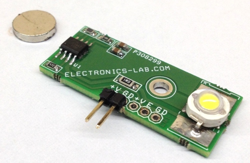
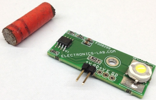
Contact-less controlled automatic wardrobe light turns on the LED when you open the wardrobe door. Τhe project is based on Hall effect IC including LED driver and tiny magnet. Board doesn’t require any mechanical switch. When magnet is close to the board, LED is off, when you open the wardrobe door magnet goes far from hall IC and its turn on the LED, the IC also has special features like soft start and soft off. This board can be used in other applications like Automotive Gloves boxes and Storage, task lighting, automotive vanity mirrors. The APS13568 is the heart of the project. The IC can drive LED current up to 150mA. I have set the current 100mA approx. with help of R3. C2 is provided to set the FADE-IN/FADE-OUT time. The value of C2 can be changed as per application requirement.
Contactless Controlled Automatic Wardrobe LED Light – [Link]
Contact-less controlled automatic wardrobe light turns on the LED when you open the wardrobe door. Τhe project is based on Hall effect IC including LED driver and tiny magnet. Board doesn’t require any mechanical switch. When magnet is close to the board, LED is off, when you open the wardrobe door magnet goes far from hall IC and its turn on the LED, the IC also has special features like soft start and soft off. This board can be used in other applications like Automotive Gloves boxes and Storage, task lighting, automotive vanity mirrors. The APS13568 is the heart of the project. The IC can drive LED current up to 150mA. I have set the current 100mA approx. with help of R3. C2 is provided to set the FADE-IN/FADE-OUT time. The value of C2 can be changed as per application requirement.
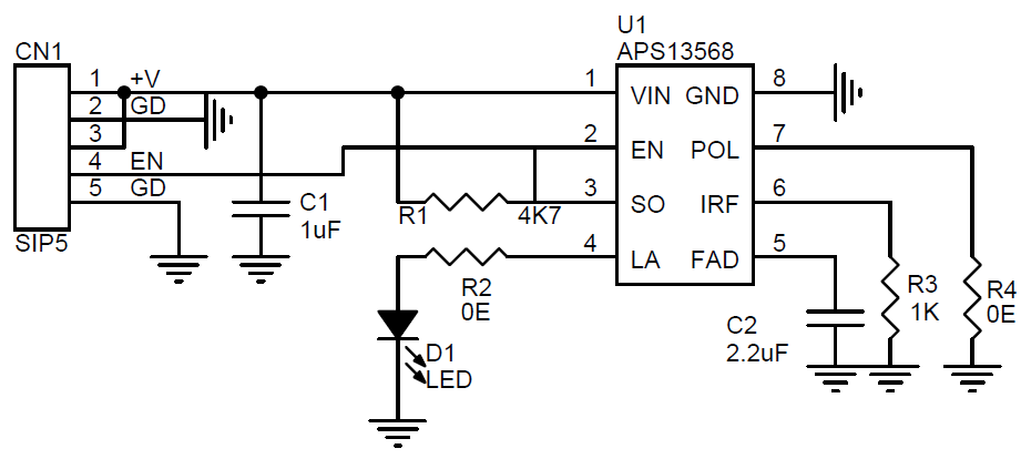
The IC is an integrated circuit that combines an ultrasensitive, Omni polar, micro power Hall-effect switch with a linear programmable current regulator providing up to 150 mA to drive high brightness LEDs. The Omni polar Hall Effect switch provides contactless control of the regulated LED current, which is set by a single reference resistor R3. This highly integrated solution offers high reliability and ease of design compared to a discrete solution. The Hall-effect switch operates with either a north or a south magnetic pole. The switch output polarity can be set with an external pull down on the POL input pin. This allows the user to select whether the APS13568 switch output goes low when a magnet is present or when the magnetic field is removed. Chopper stabilization provides low switch point drift over temperature. The LED is turned on when the EN input goes low. This active low input can be connected directly to the Hall switch output, SO, to turn the LED on when the switch output goes low. This flexible solution allows the user to connect additional slave switches, LED drivers, PWM, or microprocessor inputs to control when the LED is on. Optionally, an external capacitor can be used to adjust the fade-in/fade-out feature. On-board protection for shorts to ground and thermal overload prevents damage to the APS13568 and LED string by limiting the regulated current until the short is removed and/or the chip temperature has reduced below the thermal threshold. The integrated Hall-effect switch in the APS13568 is an Omni polar switch. The output switches when a magnetic field perpendicular to the Hall sensor exceeds the operate point threshold, BOPx (B > BOPS or B < BOPN). When magnetic field is reduced below the release point, BRPx (B < BRPS or B > BRPN), the device output goes to the other state. The output transistor is capable of sinking current up to the short-circuit current limit, IOM, which ranges from 30 to 60 mA. The difference in the magnetic operates and release points are the hysteresis, BHYS, of the device. This built-in hysteresis allows clean switching of the output even in the presence of external mechanical vibration and electrical noise. Removal of the magnetic field results in an output state consistent with B < BRPx. Since the output state polarity relative to the magnetic thresholds is user-selectable via the POL pin, reference Table 1 to determine the expected output state.
Note: The board has omnidirectional Hall sensor. Default it set to switch on the LED in absence of magnetic field or magnet is not around, it will switch off the LED when magnet is close to the hall sensor IC or in presence of magnetic field. Remove POL Resistor R4 for reverse operation.
Features
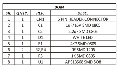
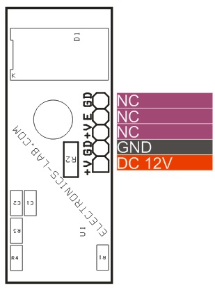
Supply 12V DC ( 7-24V Supply Possible)
LED Current 100mA (LED Current can be set to 150mA with help of R3)
Selectable Output Polarity
FADE-IN/FADE-OUT ( Soft On/Off)
Built In Short Circuit Protection, Thermal Protection, Reverse Battery and Load Dump Protection
Build the World’s Smallest Atomic Clock, Trap a Nitrogen Atom in a Carbon Cage. By Kyriakos Porfyrakis and Edward A. Laird @ ieee.org:
An atomic clock begins with an oscillator [see diagram], which creates a frequency close to the energy level of the atom being used. If the oscillator deviates from the reference frequency, the atom’s absorption pattern changes, the change is detected by a laser, and the laser’s signal is used as feedback to tune the oscillator. For the very best performance, the atoms must be electromagnetically isolated, which requires equipment that can take up entire rooms.
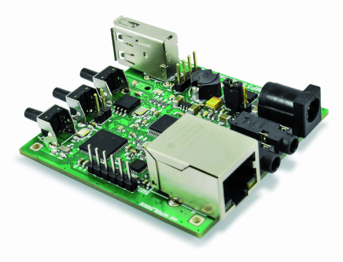
Luca Pascarella @ open-electronics.org presents how to setup their open source ethernet broadcaster. He writes:
Recently, we have presented an Ethernet audio streaming unit. In particular, we have shown how to configure the boards to work with other similar devices or with VLC Media Player, setting up a point-to-point or a broadcast streaming in all possible configurations. Also in the first episode, we analyzed the electrical circuit and the components choice. Now it is time to describe the board software advanced options and how to update firmware via Internet or manually.
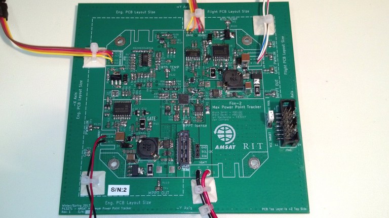
The Radio Amateur Satellite Corporation, AMSAT, recently designated RadFxSat as AO-91 after its successful deployment from a Delta II rocket as a secondary payload to NASA’s JPSS-1. RadFxSat is the first of several AMSAT satellites which are flying a Maximum Power Point Tracker (MPPT) designed and built by Brent and I as a continuation of our Rochester Institute of Technology (RIT) senior design project. The story of the Fox-1 MPPT is a great example of how amateur radio is what you want it to be.
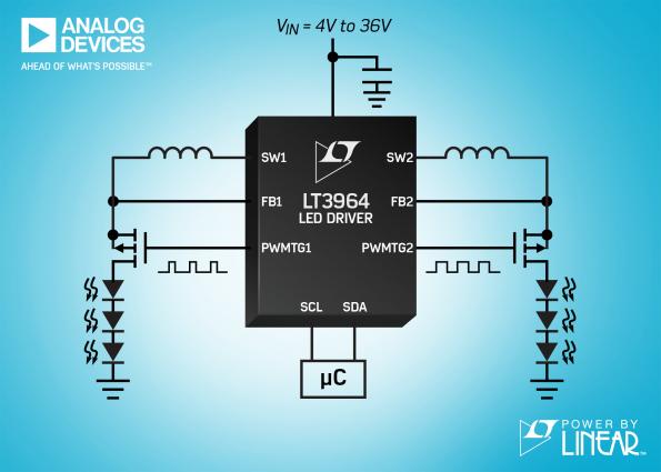
Under the “Power by Linear” branding it recently created for the product lines it acquired with its purchase of Linear Technology, Analog Devices has added the LT3964, a dual channel, 36V, high efficiency, synchronous, step-down LED driver with internal 40V, 1.6A power switches and an I2C interface that simplifies LED dimming control.
36V, 2-ch, 1.6A synchronous buck LED driver has I²C dimming – [Link]
The Internet of Things (IoT) is connecting our world together more intimately than ever. It’s also adding a whole new level of complexity and confusion on the shoulders of the electronic designer. The biggest problem is the overwhelming amount of choices and considerations that have to be made for an IoT project. Which protocol is the best? Will my chosen protocol be irrelevant a year from now? Do I have the time to design RF and an antenna? In this blog, we’ll be focusing on the topic of protocols, how they fit into the networking stack, and how you can use modules to make easy work for your first IoT project.
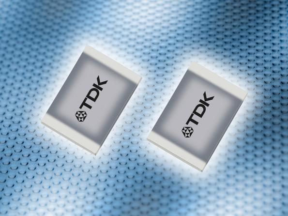
With CeraCharge, TDK has developed the world’s first solid-state battery in SMD technology. In contrast to most common battery technologies, CeraCharge works without any liquid electrolytes. by Christoph Hammerschmidt @ eenewseurope.com:
Similar to ceramic capacitors, the CeraCharge is based on multilayer technology and combines a high energy density in the smallest possible space with process reliability in the manufacture of multilayer components. The use of a ceramic solid as electrolyte also excludes the risk of fire, explosion or leakage of electrolyte fluid.
In the compact size EIA 1812, the battery, which can be rechargeable several dozen to 1000 times, offers a capacity of 100 µAh at a nominal voltage of 1.4 V depending on the requirements. In the short term, currents in the range of a few mA can also be drawn.
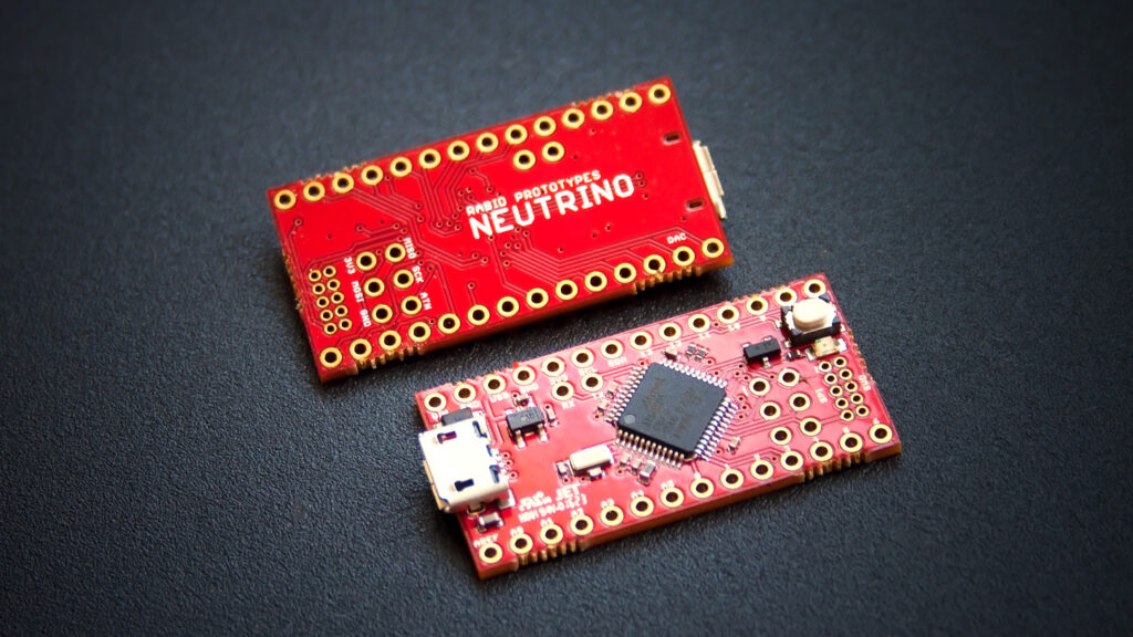
The Neutrino 3.0 is an inexpensive, open source, miniaturized version of the Arduino Zero! Featuring a 32-bit ARM processor running at 48MHz, and boasting 32K of ram, the Neutrino is far more capable than your typical Arduino. And because it has the same processor and pinout, all libraries written for the Zero will work on the Neutrino without any modification!
Technical Specs
Microcontroller: Atmel ATSAMD21G18 ARM Cortex M0+
Clock speed: 48 MHz
Operating voltage: 3.3V
I/O pin limits: 3.3V, 7 mA
Digital I/O pins: 14, with 12 PWM
Analog input pins: 6, 12-bit ADC channels
Analog output pins: 1, 10-bit DAC
Flash memory: 256 KB
SRAM: 32 KB
Voltage regulator: 3.7-5.5V input / 3.3V, 300mA output
Dimensions: 1.4 x 0.7″ (36mm x 18mm)
The project is live on kickstarter and has 14 days to go.