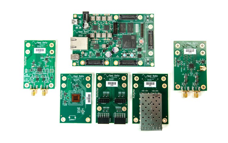
SYZYGY Brain-1 is an open source, modular ARM + FPGA development platform featuring the new SYZYGY standard for high-performance peripherals. This new development board bridges the gap between Pmods and FMCs allowing high performance peripherals to be used with ease. The author claims it’s the first realization of a carrier board supporting SYZYGY that can be used in various high performance applications. The development board is live on crowdsupply.com and has 50 days to go.
Applications
Data Acquisition
Machine Vision
Digital Communications
Software Defined Radio (SDR)
Video Output
Multi-channel I/O
Sensors
Robotics
Features and Specifications
Xilinx Zynq 7012S Single-core ARM + FPGA (dual-core 7015 optional)
667 MHz ARM Cortex-A9
55,000 programmable logic cells
2.5 Mb block memory on FPGA
120 DSP slices
Open source hardware – Schematics and PCB artwork will be available for free.
Open source software – Linux board support package sources will be available for free.
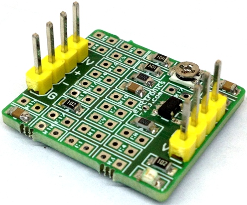
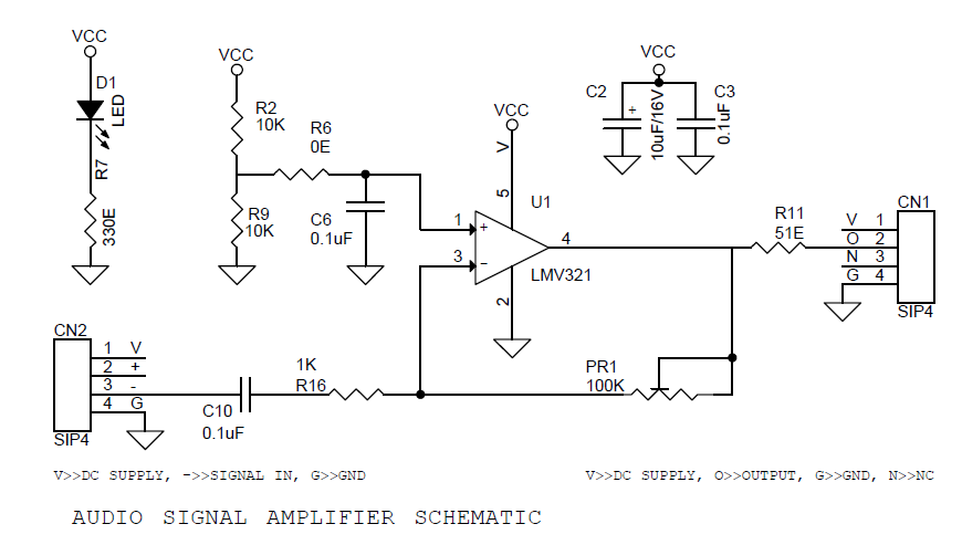
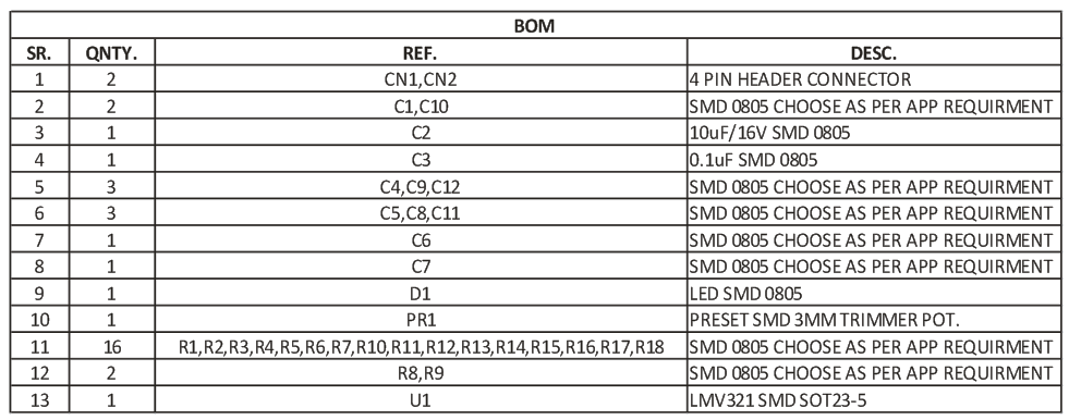
The Universal Op-Amp Development board is a general purpose blank circuit board that simplify prototyping circuits for a variety of Op-Amp circuits. The evaluation module board design allows many different circuits to be constructed easily and quickly. This board supports single SOT23-5 package. Universal single Operational Amplifier (Op-Amp) board is designed to aid in the evaluation and testing of the low voltage/low power and some precision operational amplifiers.
Universal OpAmp Evaluation Board Using LMV321 – [Link]
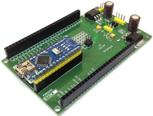
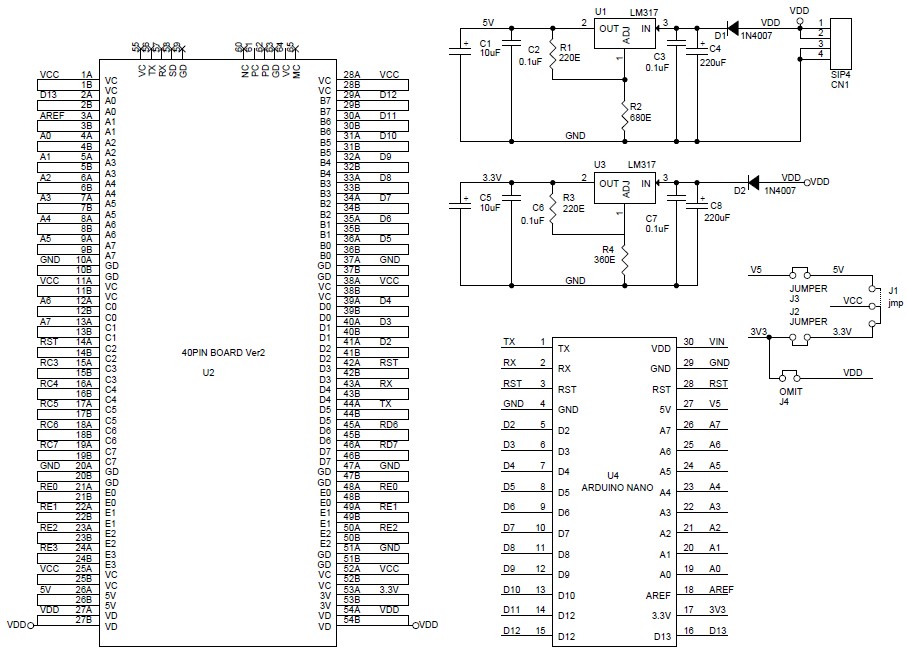
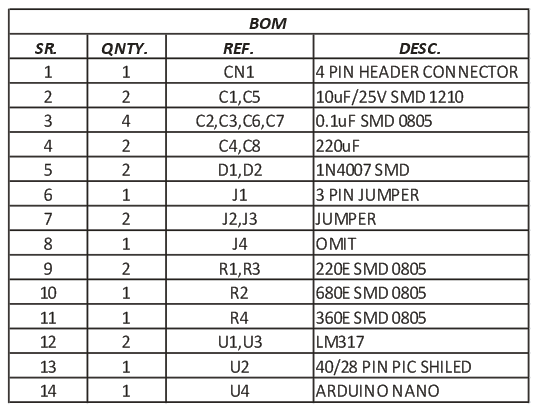
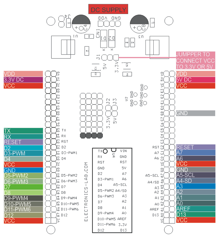
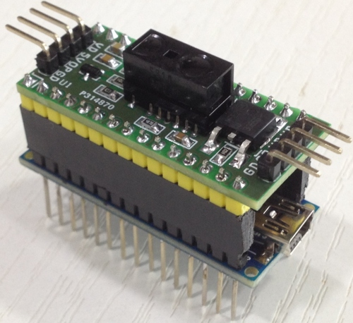
Arduino Nano to PIC40/28 PIN development shield is an extension for Arduino Nano. This project is useful to create many projects using PIC40/28PIN shield published on electronics-lab.com, refer to schematic and connection diagram to use this shield. Two on board regulators are provided which outputs 5V DC and 3.3V DC, this dual supply helps many projects which need dual supply. Jumper J1 is for supply selection VCC To 3.3V or 5V, diode provided at input of regulator for reverse supply protection. Not populated J4, Close J3 to supply 5V to Nano.
Arduino Nano to PIC40/28 PIN development shield is an extension for Arduino Nano. This project is useful to create many projects using PIC40/28PIN shield published on electronics-lab.com, refer to schematic and connection diagram to use this shield. Two on board regulators are provided which outputs 5V DC and 3.3V DC, this dual supply helps many projects which need dual supply. Jumper J1 is for supply selection VCC To 3.3V or 5V, diode provided at input of regulator for reverse supply protection. Not populated J4, Close J3 to supply 5V to Nano.
Features
Supply 7V-36V DC
On Board Dual regulator which provides 5V & 3.3V DC
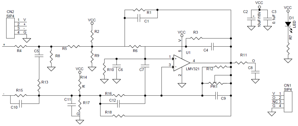
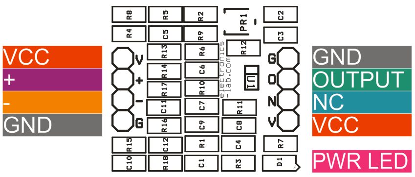
The Universal Op-Amp Development board is a general purpose blank circuit board that simplify prototyping circuits for a variety of Op-Amp circuits. The evaluation module board design allows many different circuits to be constructed easily and quickly. This board supports single SOT23-5 package. Universal single Operational Amplifier (Op-Amp) board is designed to aid in the evaluation and testing of the low voltage/low power and some precision operational amplifiers. This board will accommodate single op amp that are assembled in SOT23-5 package. It is designed to use single amplifiers. Many different circuits can be made such as inverting, non-inverting, differential-In amplifiers and low-pass, band-pass, band reject, or notch second order filters. The amplifier can be powered with single supply. These circuits can be configured without any modifications to the board, all that is necessary is to select the correct resistors and capacitors. The other optional components can be left open or shorted depending on the configuration desired. LMV321 is an ideal op-amp for this board however other single op-amp with same package and pins configuration can be used. The LMV321 device is single, low-voltage (2.7 V to 5.5 V) operational amplifier with rail-to-rail output swing. These devices are the most cost-effective solutions for applications where low-voltage operation, space saving, and low cost are needed.
Features
Supply 2.7V-5.5V (LMV321 Op-Amp)
SOT23-5 Pins Op-Amp with Pin Configuration LMV321 can be used
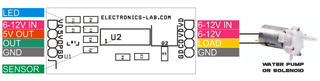
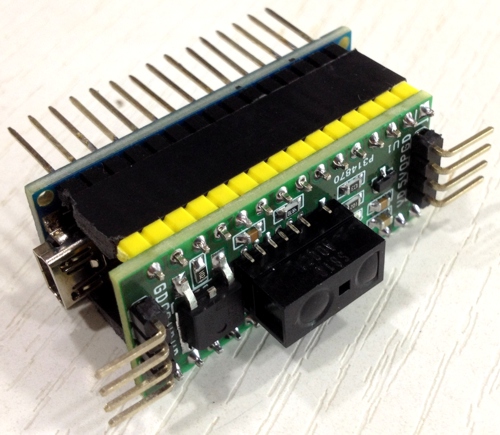
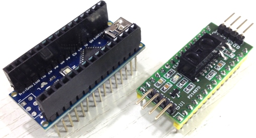
The project published here is a distance measuring sensor shield for Arduino Nano including power driver BJT transistor to drive a load like solenoid, motor or LED. This project can be used as Arduino shield or as stand-alone sensor.
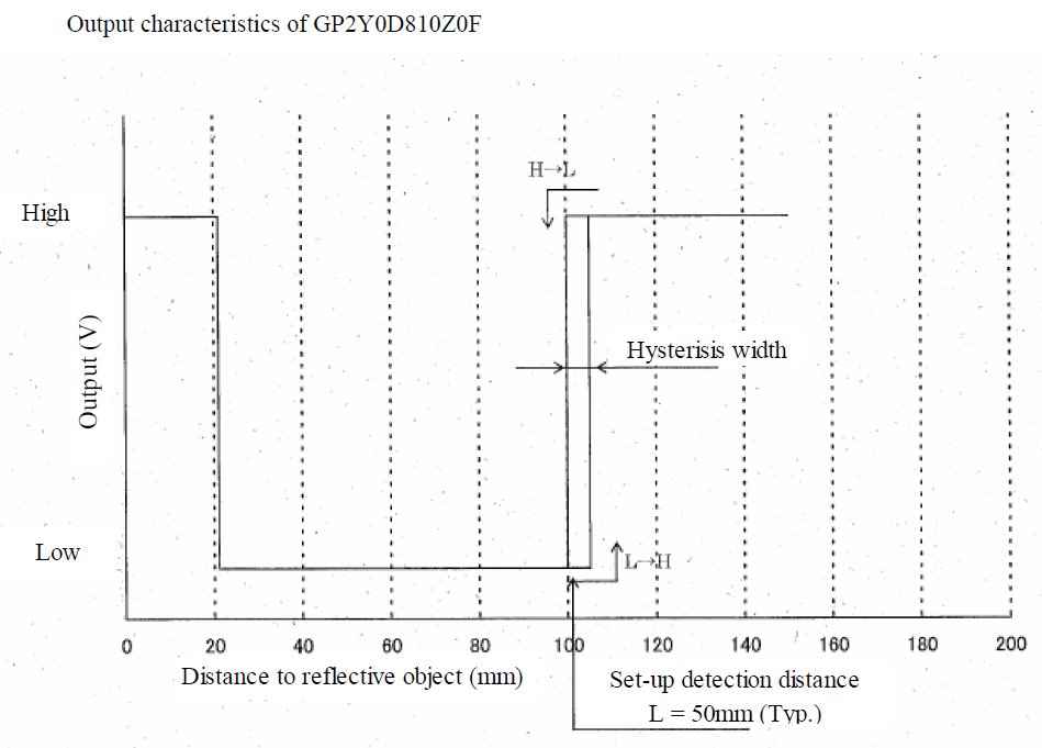
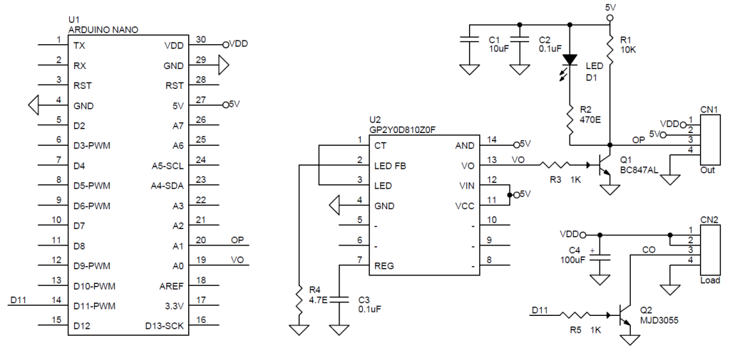
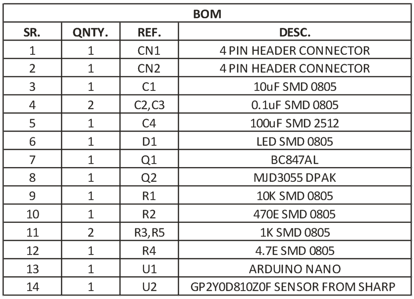
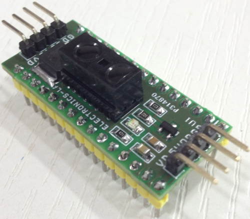
GP2Y0D810Z0F from Sharp is heart of the project, The sensor is a composed of an integrated combination of PD (photo diode) , IRED (infrared emitting diode) and signal processing circuit. The variety of the reflectivity of the object, the environmental temperature and the operating duration does not influence easily to the distance detection because of adopting the triangulation method. The output voltage of this sensor stays high in case an object exists in the specified distance range. So this sensor can also be used as proximity sensor. Output is normally High and it goes low when it detects the object. The output VO is connected to Analog pin A0 of the Arduino Nano. Q1 Transistor helps to inverse the output which also controls the LED. This inversed output also connected to Analog pin A1 of Arduino. Digital pin D11 goes to base of Q2 power NPN BJT transistor MJD3055. This transistor provided to develop high power load driving application like Auto flush, Auto LED on/off when object is detected etc.
Distance Measuring Sensor Shield for Arduino Nano Using GP2Y0D810Z0F – [Link]
The project published here is a distance measuring sensor shield for Arduino Nano including power driver BJT transistor to drive a load like solenoid, motor or LED. This project can be used as Arduino shield or as stand-alone sensor.
GP2Y0D810Z0F from Sharp is heart of the project, The sensor is a composed of an integrated combination of PD (photo diode) , IRED (infrared emitting diode) and signal processing circuit. The variety of the reflectivity of the object, the environmental temperature and the operating duration are not influenced easily to the distance detection because of adopting the triangulation method. The output voltage of this sensor stays high in case an object exists in the specified distance range. So this sensor can also be used as proximity sensor. Output is normally High and it goes low when it detects the object. The output VO is connected to Analog pin A0 of the Arduino Nano. Q1 Transistor helps to inverse the output which also controls the LED. This inversed output also connected to Analog pin A1 of Arduino. Digital pin D11 goes to base of Q2 power NPN BJT transistor MJD3055. This transistor provided to develop high power load driving application like Auto flush, Auto LED on/off when object is detected etc.
Features
Supply 5V (2.7V To 6.2V Standalone Mode)
Current Consumption 10mA
Detection Range 20MM- 100MM
Sun Light Tolerance
Output LED
Measuring Operating Duration 1.28ms
Measuring Duration V Output 2.56ms
Application
Touch less Switch
Sanitary Equipment
Robot Cleaner
Control of Illumination
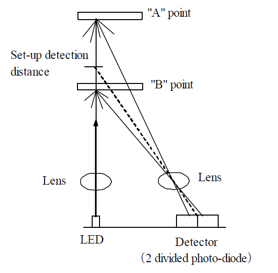
Operation Of Sensor
Optical spot position on the detector (2 divided photo-diode) shall be changed when reflective object is at “A” point and at “B” point. In case that the position of the photodiodes is set as the reflected light at the setup detection distance makes a spot on the center of the photodiodes, the reflected light at “A” point comes onto the left photodiode and the reflected light at “B” point comes onto the right photodiode. So by processing the detecting light amount ratio between these two photodiodes, this sensor can judge as detection at “B” point and a non-detection at “A” point.
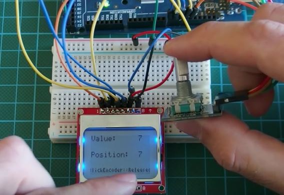
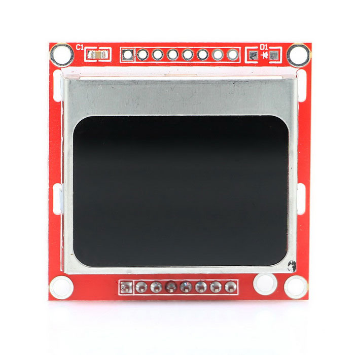
Today we will take a look at using a rotary encoder with Arduino and displaying rotation data on the Nokia 5110 LCD display.
A rotary encoder is an Electro-mechanical device that converts angular position or the rotation of a shaft into analog or digital values. By turning the shaft to the right or left, we either get an increase or decrease in value. One of the major advantage of rotary encoders is the fact that rotation is limitless. If the maximum position, (which is 20 for the particular rotary encoder used in this tutorial) is reached, the device starts the position counting all over again while the Value attached to the position continues to increase/decrease with every turn of the knob in the same direction. This means we could still keep increasing the value associated with turning the rotary encoder so far we keep rotating in the same direction.
Rotary Encoder with Arduino and Nokia 5110 LCD Tutorial – [Link]
Today we will take a look at using a rotary encoder with Arduino and displaying rotation data on the Nokia 5110 LCD display.
A rotary encoder is an electro-mechanical device that converts angular position or the rotation of a shaft into analog or digital values. They are mainly of two types, absolute and incremental rotary encoders. The output of the absolute encoders indicates the current position of the shaft, making it more of an angle transducer. The output of incremental encoders provides information about the motion of the shaft, this can then be further processed to give information such as speed, distance and position among others.
By turning the shaft to the right or left, we either get an increase or decrease in value. One of the major advantage of rotary encoders is the fact that rotation is limitless. If the maximum position, (which is 20 for the particular rotary encoder used in this tutorial) is reached, the device starts the position counting all over again while the value attached to the position continues to increase/decrease with every turn of the knob in the same direction. This means we could still keep increasing the value associated with turning the rotary encoder so far we keep rotating in the same direction.
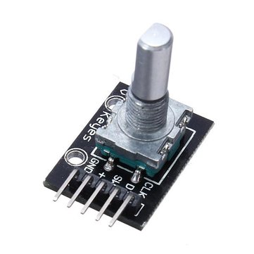
Rotary Encoder
Rotary encoders are used in many applications that require precision and limitless rotation, like industrial controls, Robotics, computers and micro-controller based applications like the one we are working on today.
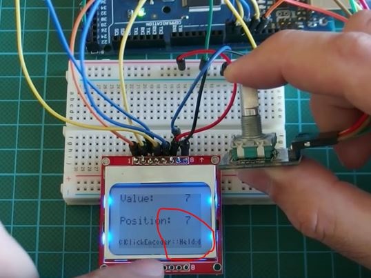
Click held
Another good thing about this rotary encoder is the fact that it comes with a button attached so you can click by pressing the nob as shown in the image below and the click/press will be recognized by the Arduino like a button input press, just as it will if it were any other button.
Click Released
When the button is clicked and held down, Arduino will recognize that and when released the Arduino will also recognize it has been released.
This feature makes the rotary encoder very useful and versatile.
Project parts
For this project, we will need the following components.
These components can be bought from the links attached.
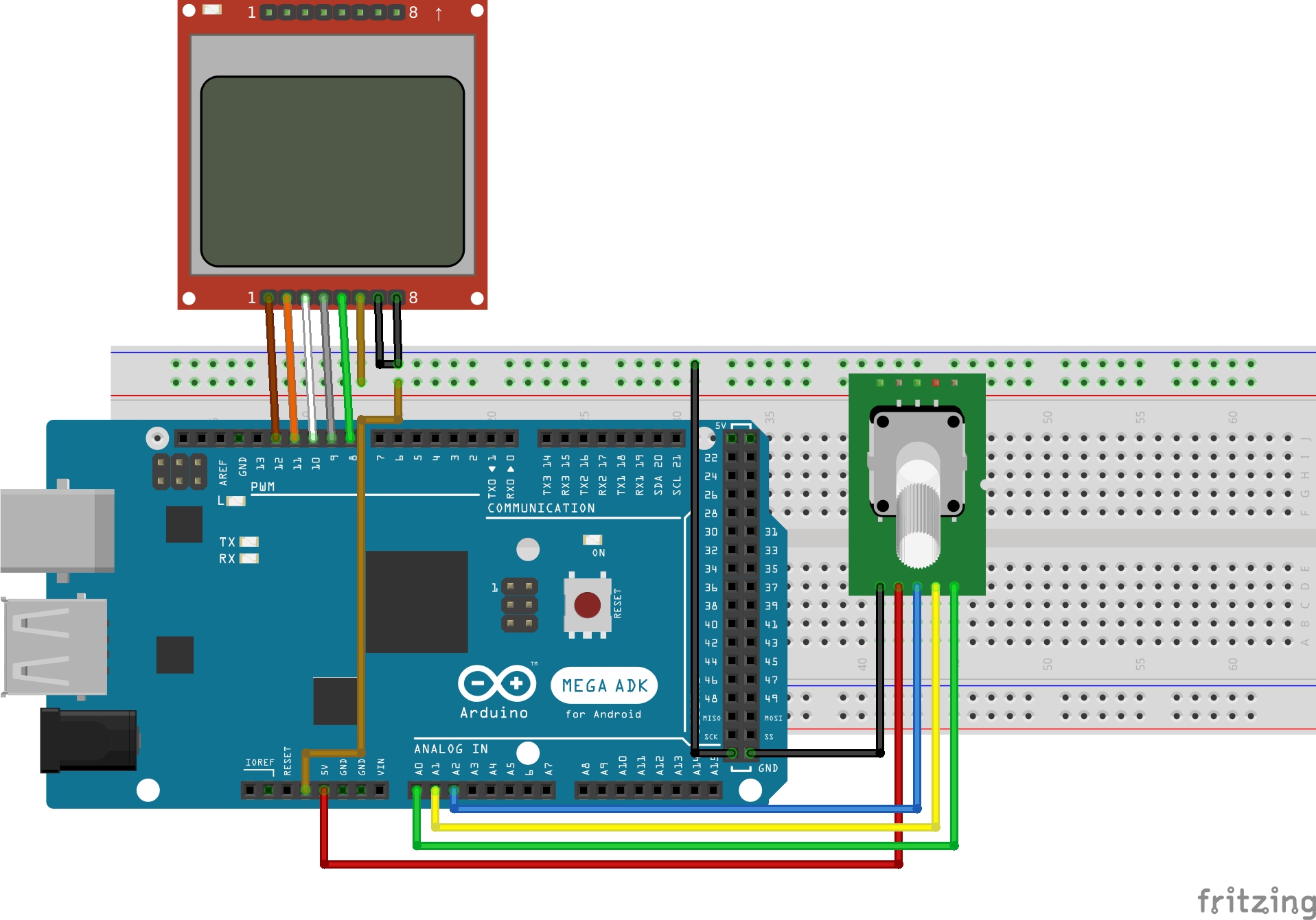
Schematics
Its time to connect the components as described.
The rotary encoder used in this tutorial is available on ebay for $1 – $2. This rotary encoder has 20 positions and it can be clicked as earlier described. It has 5 pins and it is connected to the Arduino as shown in the schematics below.
from the last tutorial, we went through the connection for the LCD but just in case you missed it, connect the LCD also as shown in the schematics above.
The light pin, when connected to ground turns the backlight “ON” while connecting it to VCC turns it “OFF”.
The display has two sides to which the headers pins can be connected. You can pick one of the sides and solder header pins so that the display can fit firmly on the breadboard. This display works best when on 3.3 volts, so its probably best to power it with 3.3v.
With all connected. we can move to write the code.
Code
The code for this project is heavily dependent on the Timerone and the encoder libraries which can be downloaded from the links attached to them. Install these libraries in your arduino IDE and launch the IDE to start coding. You can learn how to install Arduino Libraries from several other tutorials on this website.
Before I drop the entire code, as usual, here is a code breakdown to show why each part of the code is important.
This first few lines of code below include all the needed libraries for this code. Without the libraries, it would have been more time consuming than normal so we say thank you to the authors of these wonderful libraries.
//Written by Nick Koumaris
//info@educ8s.tv
//educ8s.tv
#include <ClickEncoder.h>
#include <TimerOne.h>
#include <LCD5110_Graph.h>
After including the Libraries the next thing we did was perform necessary setups to use the LCD like declaring the pins to which it is connected and setting up the fonts to be used.
We round up the declaration by creating an encoder object and the variable value.
ClickEncoder *encoder;
int16_t last, value;
The timerisr() function uses the encoder service function
void timerIsr() {
encoder->service();
}
We then proceed to the setup function.
The first thing we did under the setup function was to handle the initialization of the LCD, then setting up the font we in which we would like the text to be displayed.
lcd.InitLCD();
lcd.setFont(TinyFont);
We then display an introductory message “Rotary encoder” with the added center parameter indicating we want it printed at the center of the screen. We print “demo” immediately after it then the lcd.update method is called to display the rotary encoder followed by demo on the screen.
We then set a delay to allow the text to spend some time on the screen.
After the delay, we proceed to create the click encoder object with the pins to which our encoder was connected as parameters.
delay(2000);
lcd.setFont(SmallFont);
encoder = new ClickEncoder(A1, A0, A2);
encoder->setAccelerationEnabled(false);
After the setup function, we move to the loop function. The first few lines of code within the loop function handles the creation of variables that will be used later in the code, the include encoder value which increases when the encoder is turned continuously in the same direction and the encoder position which goes from 0 to 20, but since our encoder has no rotational limit, it starts again from zero.
void loop() {
int encoderValue;
int encoderPosition;
lcd.setFont(SmallFont);
char encoderValueArray[3];
char encoderPositionArray[3];
The value variable is increased by each turn of the rotary encoder (increase in position).
value += encoder->getValue();
The next part of the code handles the display of the value generated from the rotation of the encoder and the position of the rotation.
With the rotary part handled, the next part of the code handles the click event. The click event is in four forms; pressed, Held, Released, click and double click. Each of this action was programmed to display its status at the bottom of the screen.
ClickEncoder::Button b = encoder->getButton();
if (b != ClickEncoder::Open) {
#define VERBOSECASE(label) case label:lcd.setFont(TinyFont);lcd.print(#label,CENTER,40);lcd.update(); break;
switch (b) {
VERBOSECASE(ClickEncoder::Pressed);
VERBOSECASE(ClickEncoder::Held)
VERBOSECASE(ClickEncoder::Released)
VERBOSECASE(ClickEncoder::Clicked)
case ClickEncoder::DoubleClicked:
encoder->setAccelerationEnabled(!encoder->getAccelerationEnabled());
break;
The projects complete code is found below and in the attachment at the end of the tutorial.
//Written by Nick Koumaris
//info@educ8s.tv
//educ8s.tv
#include <ClickEncoder.h>
#include <TimerOne.h>
#include <LCD5110_Graph.h>
LCD5110 lcd(8,9,10,12,11);
extern unsigned char SmallFont[];
extern unsigned char TinyFont[];
ClickEncoder *encoder;
int16_t last, value;
void timerIsr() {
  encoder->service();
}
void setup() {
lcd.InitLCD();
lcd.setFont(TinyFont);
lcd.print("Rotary Endcoder",CENTER,0);
lcd.print("DEMO",CENTER,20);
lcd.update();
delay(2000);
lcd.setFont(SmallFont);
encoder = new ClickEncoder(A1, A0, A2);
encoder->setAccelerationEnabled(false);
Timer1.initialize(1000);
Timer1.attachInterrupt(timerIsr);
last = -1;
}
void loop() {
  int encoderValue;
  int encoderPosition;
  lcd.setFont(SmallFont);
  char encoderValueArray[3];
  char encoderPositionArray[3];
value += encoder->getValue();
if (value/4 != last) {
    encoderValue = value/4;
    encoderPosition = encoderValue%20;

    last = encoderValue;

    lcd.clrScr();
    lcd.print("Value: ",LEFT,0);
    dtostrf(encoderValue, 3, 0, encoderValueArray);
    lcd.print(encoderValueArray,LEFT+55,0);

    dtostrf(encoderPosition, 3, 0, encoderPositionArray);
    lcd.print("Position:",LEFT,20);

    if(encoderPosition <0)
      encoderPosition = -encoderPosition;
    lcd.print(encoderPositionArray,LEFT+55,20);

    //Serial.print("\n");
    lcd.update();
  }
ClickEncoder::Button b = encoder->getButton();
 if (b != ClickEncoder::Open) {
   #define VERBOSECASE(label) case label:lcd.setFont(TinyFont);lcd.print(#label,CENTER,40);lcd.update(); break;
   switch (b) {
     VERBOSECASE(ClickEncoder::Pressed);
     VERBOSECASE(ClickEncoder::Held)
     VERBOSECASE(ClickEncoder::Released)
     VERBOSECASE(ClickEncoder::Clicked)
     case ClickEncoder::DoubleClicked:
         encoder->setAccelerationEnabled(!encoder->getAccelerationEnabled());
       break;
}
}
}
Copy the code into your Arduino IDE after library installation and upload to the Arduino board. It should work like a charm.
The code is also attached as a zip file at the bottom of this tutorial.
You can watch the video tutorial of this project on youtube here.
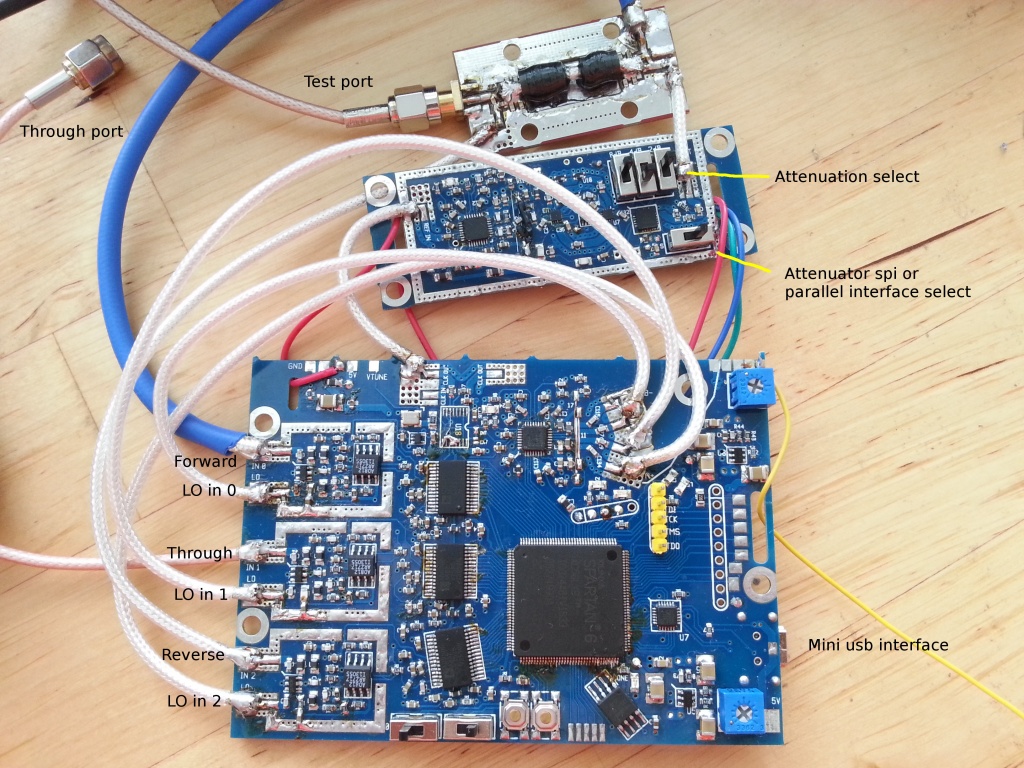
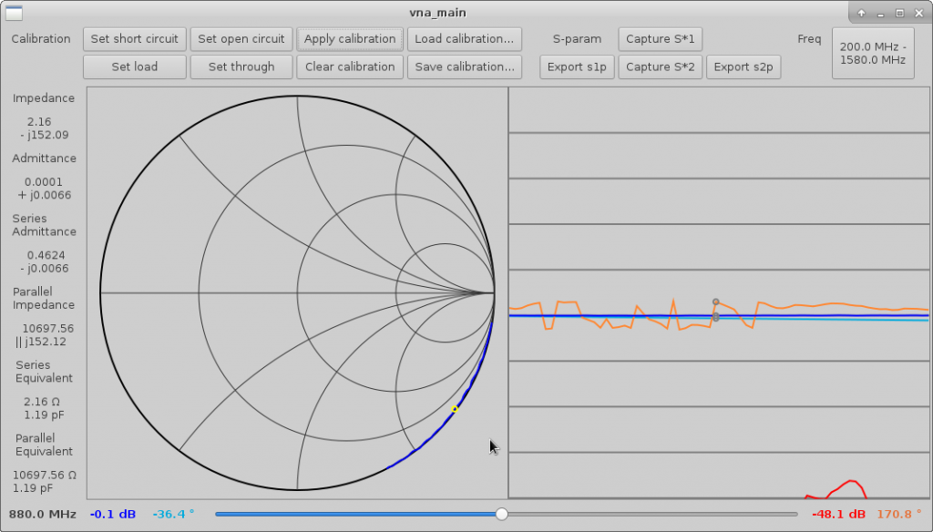
xaVNA is a simple and cheap vector network analyzer that allows you to easily tune up antennas, filters, and amplifiers by plugin it to USB. It is able to display smith charts/graphs on the including PC software.
The main board connects to a PC through usb and communicates via a virtual serial port device; the PC software sets the frequency and other parameters by sending two-byte register write commands, and the device sends averaged vector values representing magnitude and phase of measured wave.
The project is open source and available on github and a kickstarter campaign is live with 31 days to go.
Specifications
Frequency range: guaranteed 137MHz – 2500MHz, typical 135MHz – 3500MHz
Measurement signal level (controlled using on-board switches, iteration 1 board only): -5dBm to 10dBm, with 2dB increments
Measurement signal level (controlled using spi interface): -20dBm to 10dBm, with 1dB increments
3 receivers: forward coupled, reverse coupled, through; can measure S11 and S21 of a two port device. To measure S22 and S12 the DUT needs to be manually reversed.