Mecpow X3 Pro: Unveiling its High-Precision Engraving Magic

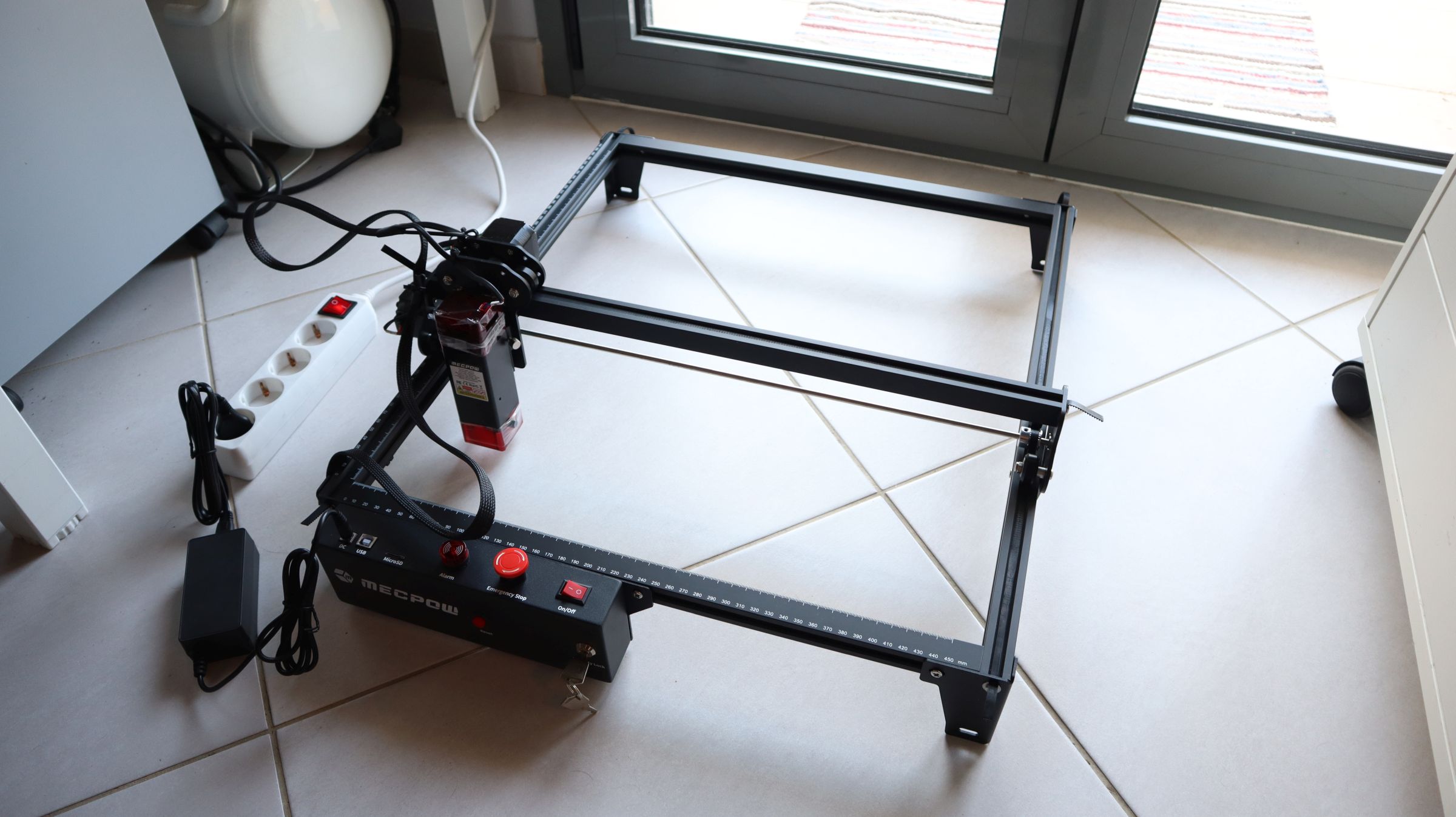
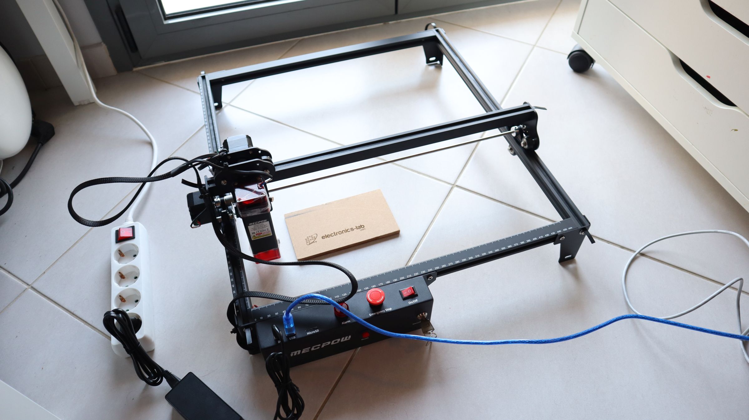
Whether you’re a hobbyist, a business owner, or a DIY enthusiast, a laser engraver becomes a convenient tool if you are into creating custom designs. It allows you to develop custom-engraved products using various materials, such as wood, acrylic, leather, fabric, and even certain types of metal. But with so many models in the market, sometimes it becomes tough to figure out which is the best for you, so we want to introduce you to Mecpow X3 Pro, a module laser engraver with an extendable engraving area.

Yes! You read that right; this engraver has an extendable engraving aria, the standard dimension of 400mm x 410mm, but with some modification, it can extend up to 400mm x 750mm. That is a massive boost for your projects. It also has an air assist and pump, precision stepper motors, a large extendable engraving area, and user-friendly software support. All these features make the Mecpow X3 Pro an extraordinary tool for your engraving projects while offering remarkable value for its price.
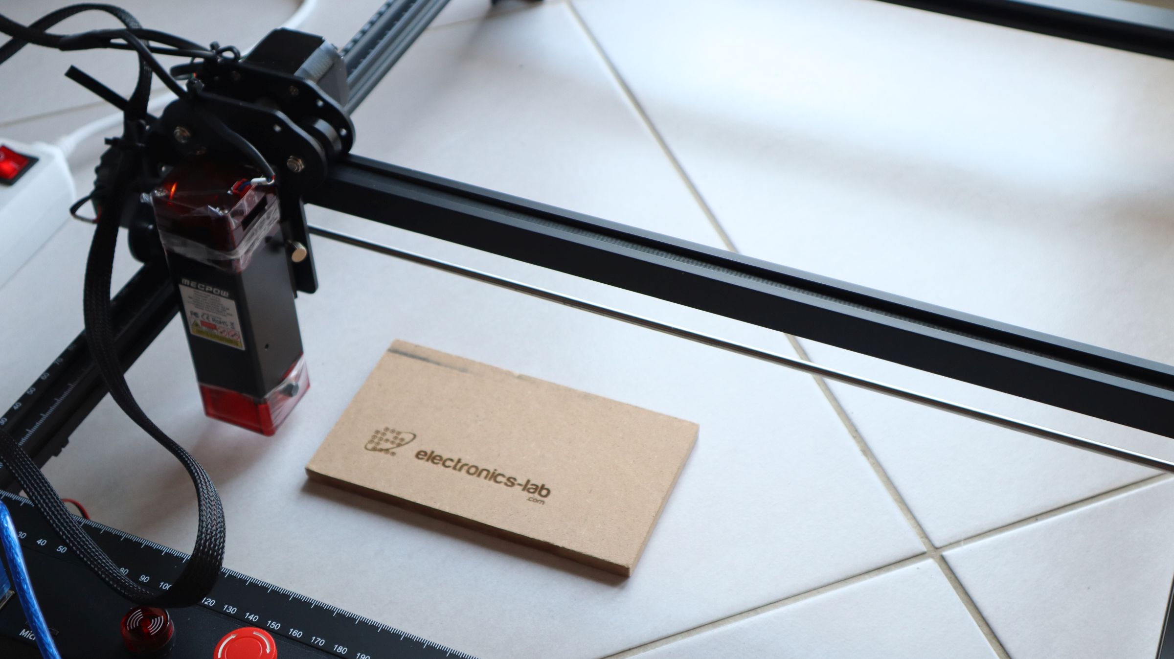
The Laser Diode

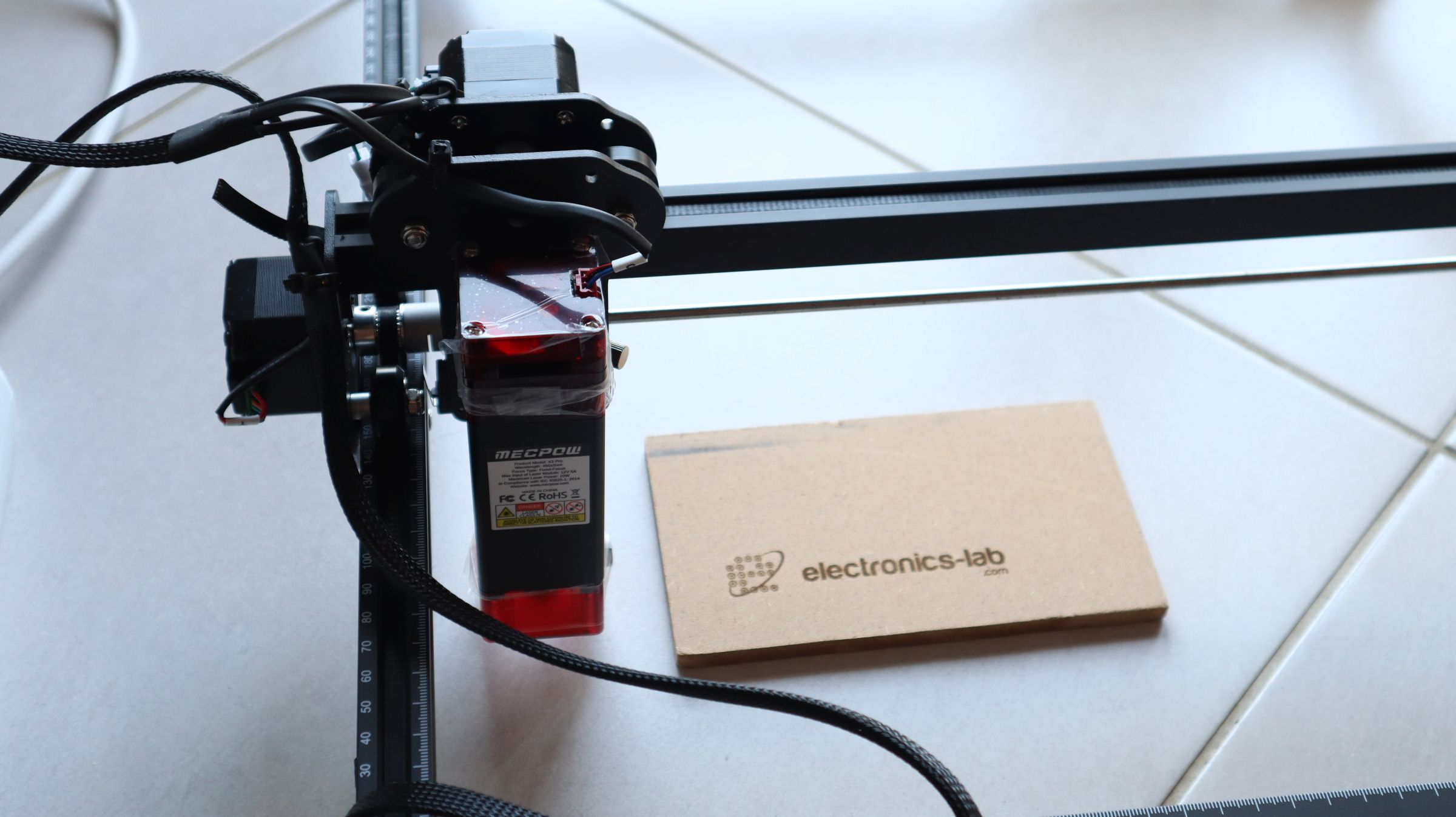
The Mecpow X3 Pro has a powerful laser diode that can output up to 10W of laser power. The laser diode is a fixed-focus diode which means it’s reliable and almost maintenance-free. Additionally, it claimed to have a rectangular beam spot shape of 0.08mm x 0.06mm, which is impressive compared to other lasers in this category.

Fixed focus means no moving parts in the laser, unlike those which use mirrors and reflectors to divert the laser beam. That also means the beam width is narrower, and the engraver is almost maintenance-free.

It’s also shocking to see how small the laser head is compared to other laser engravers. Because of that, this engraver can reach an engraving speed of 100,000 mm/min, which is very high compared to others. But the most fascinating thing about this engraver is its engraving accuracy of 0.01mm. That is game-changing because a fast engraver tends to lag precision.

This laser cutter houses a powerful 10W laser that can cut various materials. For instance, it can cut 20mm pine wood, 15 mm black acrylic, and even 0.1 mm stainless steel in a single pass. It can do multiple passes to cut thicker materials and still produce a clean cut thanks to its revolutionary 0.01mm accurate laser beam.

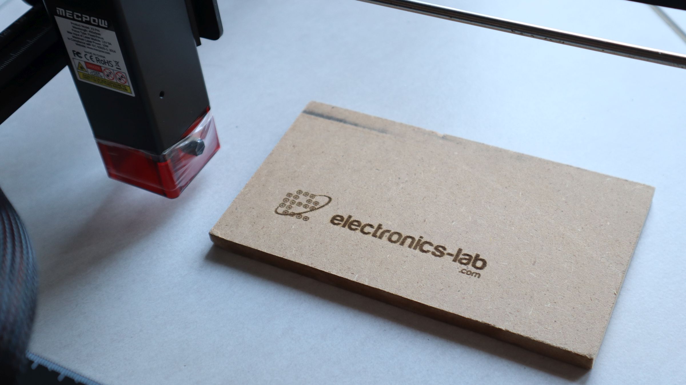
The Focusing Procedure

One of the pain points of any laser engraver is its focusing process; that is why the developers of Mecpow came up with a unique workaround, and it’s done with the help of the included focusing plate.

To adjust the focus, you place the focusing screen on top of the object now move the laser head down until the laser head touches the focusing plate, and your focusing is done. That’s how easy it is to do the focus for this machine.

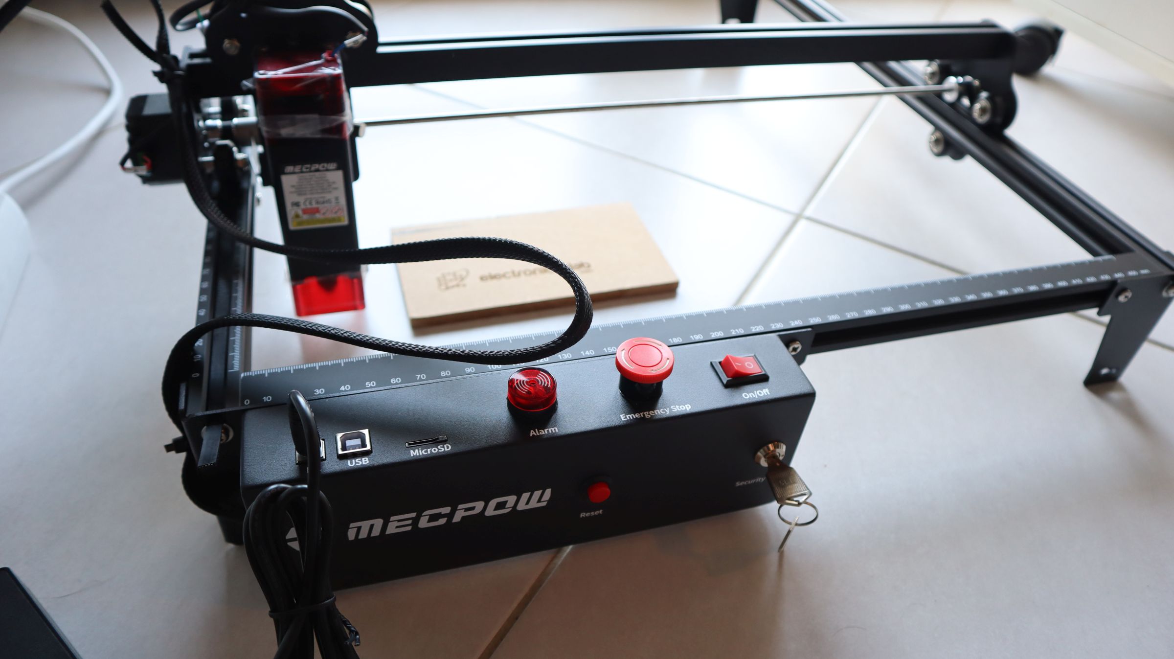
Special Features and Safety Measures

This laser engraver/cutter includes various special features, like Extendable Engraving Space, an Eye Protector shield, Air Assist, and more. It also includes safety features like Emergency Stop Button, Limit Switches, Fire Sensor, Alarm, and more.

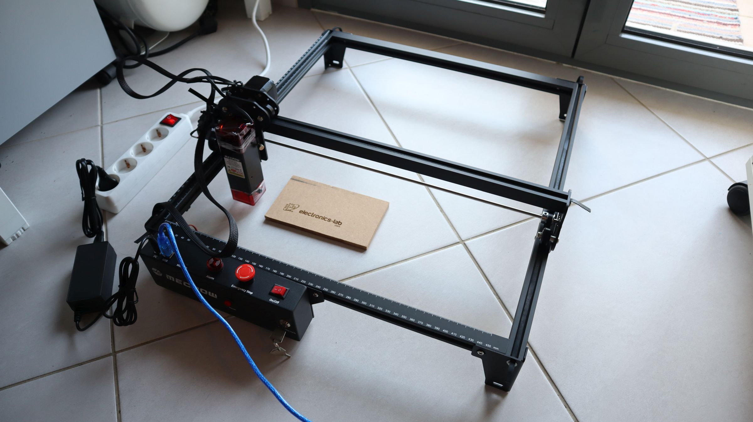
Extendable Engraving Area

This engraver’s most interesting takeaway is its ability to expand its engraving area. The engraver has a standard engraving space of 400mm x 410mm, but with a kit, you can increase it to 750mm x 400mm.

It also features a built-in laser shield for better eye protection. The built-in laser shield filters out 98% UV light to protect your eyes. You will get a pair of laser safety glasses in the box for additional eye protection.

The Air Assist Pump

The Mecpow X3 Pro offers a fully controllable air assist pump that can be turned on and off automatically or controlled through Lightburn. The air assist pump increases cutting precision and quality by removing debris and smoke for a clear cut. It also blows out the additional combustible gasses, reducing the fire risk.

Other safety features include a Flame Sensor, an emergency stop button a gyroscope sensor to detect tilt. If the machine tilts more than 50±5°, the control board stops the machine to prevent damage. It also features a Security lock and bump protection for added security.

The limit switch feature is the best feature a laser engraver could have. With a limit switch, you can set a home command, and the printer head will go to the home position, just like a 3D printer would. It also helps a machine start from the same place every time, even after interruptions.

Software Support

The Mecpow X3 Pro is compatible with the free LaserGRBL software, though it can be somewhat laggy. I prefer LightBurn, which is well-organized and intuitive. However, LightBurn isn’t free. After a 1-month trial, there’s a $60 license fee. Despite the cost, it’s valuable because it significantly saves time.

With LaserGRBL, you can import vector files (NC, BMP, JPG, PNG, DXF…) and bitmap image files (BMP, jpg, png and gif), but with Lightburn, you have support for more formats like AI, SVG, DXF, PDF, HPGL, PLT, and RD for vector formats and PNG, JPEG, BMP, TIFF, TGA, and GIF for image formats.

For any laser engraver, a vector file is preferred because it guides the laser along the shape’s edges directly. This is faster than the dot-making method used for bitmap images.

You can find many free vector designs online and use programs like Inkscape or QCAD to create them. Additionally, you can download free vectors or purchase unique designs from sites like Etsy to enhance your work.

The laser engraver comes with various tools and accessories to get you started. You will get an air assist pump, user manual, adapter, controller, screws, screwdriver, Allen key, brackets, aluminum guide rods, and more in the box. All these components together provide a seamless engraving experience.

Video

Purchase:

If you’re interested in purchasing the Mecpow X3 Pro 10W Laser Engraver with Air Assist Kit, you can use any of the links above. In any case, the price will be $279.99 no matter the platform choice.  Don’t miss out on this great deal!

4 Channel Current Sense Amplifier – Low and High-Side Voltage Output

This 4-Channel current sense amplifier is designed for cost-optimized applications. This is a current-sense amplifier (also called a current-shunt monitor) that senses the voltage drop across current-sense resistors at common-mode voltages from –0.2 V to +26 V, independent of the supply voltage. The project was built using INA4180 chip which integrates a matched resistor gain network in four, fixed-gain 20V/V, this matched gain resistor network minimizes gain error and reduces the temperature drift. The board operates with a single 2.7-V to 5.5-V power supply. The four-channel INA4180 draws a maximum supply current of 900 µA. Resistors R2, R6, R8, R12, R3, R7, R9, R13 and Capacitor C3, C4, C5, C6 used as input filters. The gain of the amplifier is 20V/V, and external input resistors resulting a 0.9% gain error.

Gain Selection

  • INA4180A1 Gain 20V/V
  • INA4180A2 Gain 50V/V
  • INA4180A3 Gain 100V/V
  • INA4180A4 Gain 200V/V
Gain: The board is populated with an INA4180A1 chip that has a gain of 20V/V, the user may choose any of the above chips with a higher gain.
Note: Shunt Resistor 0.01Ω with 20/V Gain Amplifier, Output = 0.2 V/A + Input Filter Circuit Error

Features

  • Operating Power Supply 2.7V to 5V DC 10mA
  • Output 0.2V/A (2V @ 10Amps)
  • Common-mode voltage -0.2V To 26V
  • Input offset (±) (max) (µV) 150
  • Input offset drift (±) (typ) (µV/°C) 0.2
  • Voltage gain (V/V) 20
  • CMRR (min) (dB) 84
  • Bandwidth (kHz) 350
  • Gain error (%) 8
  • Gain error drift (±) (max) (ppm/°C)20
  • On Board Power LED
  • Screw Terminal for Current Sense Load
  • Header Connector for Logic supply and Outputs
  • PCB Dimensions 47.78 x 36.20 mm
  • 4 x 2.5MM Mounting Holes

Connections and Other Details

  • CN1: Pin 1 = VCC 2.7V to 5.5V Dc Input, Pin 2 = Output 1, Pin 3 = Output 2, Pin 4 = Output 3, Pin 5 = Output 4, Pin 6 = GND
  • CN2: Pin 1 = Load 1, Pin 2 = GND, Pin 3 = DC 1 Input
  • CN3: Pin 1 = Load 4, Pin 2 = GND, Pin 3 = DC 4 Input
  • CN4: Pin 1 = Load 2, Pin 2 = GND, Pin 3 = DC 2 Input
  • CN5: Pin 1 = Load 3, Pin 2 = GND, Pin 3 = DC 3 Input
  • D1: Power LED

RSENSE and Device Gain Selection

The project is tested with 4 x 0.01Ω/3W current resistors, considering approx. current sense range up to 10A. The users may choose the appropriate current sense resistor and Amplifier with different gains as per requirement. Refer to the datasheet of the chip for more info. The accuracy of the INA4180 is maximized by choosing the current-sense resistor to be as large as possible. A large sense resistor maximizes the differential input signal for a given amount of current flow and reduces the error contribution of the offset voltage. However, there are practical limits as to how large the current-sense resistor can be in a given application. The INA4180 has a typical input bias current of 80 µA for each input when operated at a 12V common-mode voltage input. When large current-sense resistors are used, these bias currents cause increased offset error and reduced common-mode rejection. Therefore, using current-sense resistors larger than a few ohms is generally not recommended for applications that require current-monitoring accuracy. A second common restriction on the value of the current-sense resistor is the maximum allowable power dissipation that is budgeted for the resistor.

Schematic


Parts List

NOQNTY.REF.DESC.MANUFACTURERSUPPLIERSUPPLIER PART NO
11CN16 PIN MALE HEADER PITCH 2.54MMWURTHDIGIKEY732-5319-ND
24CN2,CN3,CN4,CN53 PIN SCREW TERMINAL PITCH 5.08MMPHOENIXDIGIKEY277-1248-ND
31C1100nF/50V CERAMIC SMD SIZE 0805YAGEO/MURATADIGIKEY
41C210uF/25V CERAMIC SMD SIZE 1206YAGEO/MURATADIGIKEY
54C3,C4,C5,C6100PF/50V CERAMIC SMD SIZE 0805YAGEO/MURATADIGIKEY
61D1LED RED SMD SIZE 0805OSRAMDIGIKEY475-1278-1-ND
71R11K 5% SMD SIZE 0805YAGEO/MURATADIGIKEY
88R2,R3,R6,R7,R8,R9,R12,R1310E 5% SMD SIZE 0805YAGEO/MURATADIGIKEY
94R4,R5,R10,R110.01E/3W 1% SMD SIZE 2512BORNS INCDIGIKEYCRA2512-FZ-R010ELFCT-ND
101U1INA4180A1IPWRTIDIGIKEY296-49094-1-ND

Connections

Gerber View

Photos

Video

INA4180A1 Datasheet

48V DC Input to 12V Output DC-DC Converter

This DC/DC buck regulator project is based on LMR38020 chip that employs synchronous rectification to achieve high conversion efficiency on a small board. The project operates over a wide input voltage range of 14V to 48V to provide a regulated 12Vdc output at 400kHz switching frequency. The output voltage has better than 1.5% setpoint accuracy. Enable pin is connected to VIN using resistor R2. The device has built-in protection features such as cycle-by-cycle current limit, hiccup mode short-circuit protection, and thermal shutdown in case of excessive power dissipation.

Features

  • Tightly regulated output voltage of 12 V with 1.5% setpoint accuracy
  • Load Current 1Amp (Can provide Up to 2A), limited due to PCB thermal area.
  • Wide input voltage operating range of 14 V to 48 V
  • 98% maximum duty cycle
  • Operating Frequency 400Khz
  • Force PWM operation to achieve low output voltage ripple, tight output voltage regulation at light load
  • Frequency synchronization to external clock
  • Thermal Shutdown (Threshold 163 Degree Centigrade)
  • Hiccup Mode Short-Circuit Protection
  • Supports Start-up with Pre-Biased Output
  • Cycle-by-cycle overcurrent protection
  • PCB Dimensions 29.05 X 25.88 MM

The project provides 12V output with a maximum of 48V input. The input voltage is limited due to the input capacitor voltage rating. The input and output voltage can be changed with a few component adjustments. The IC has a wide input voltage range. The board can support a higher input power supply. Output also can be altered as per user requirements. Refer to the details below for various options. Also, refer to the datasheet of LMR38020 for more info.

12V DC Output, 48V DC Input

  • Output Capacitor C2, C3, C4 10uF/10V Ceramic SMD Size 1210
  • C5 1nF/10V Ceramic SMD Size 0805
  • Resistor R5 100K 1% SMD Size 0805 (Output Feedback Divider Resistor)
  • Resistor R4 9.09K 1% SMD Size 0805 (Output Feedback Divider Resistor)
  • Resistor R3 64.5K 1% SMD Size (Frequency) 400Khz
  • Inductor L1 33uH/5Amp 12x12mm SMD

5V DC Output, 48V DC Input

  • Output Capacitor C2, C3, C4 22uF/10V Ceramic SMD Size 1210
  • C5 1nF/10V Ceramic SMD Size 0805
  • Resistor R5 100K 1% SMD Size 0805 (Output feedback Divider Resistor)
  • Resistor R4 24.9K 1% SMD Size 0805 (Output feedback Divider Resistor)
  • Resistor R3 64.5K 1% SMD Size 0805 (Frequency) 400Khz
  • Inductor L1 15uH/5Amp 12x12mm SMD

24V DC Output, 48V DC Input

  • Output Capacitor C2, C3, C4 10uF/10V Ceramic SMD Size 1210
  • C5 1nF/10V Ceramic SMD Size 0805
  • Resistor R5 100K 1% SMD Size 0805 (Output feedback Divider Resistor)
  • Resistor R4 4.32K 1% SMD Size 0805 (Output feedback Divider Resistor)
  • Resistor R3 52.3K 1% SMD Size 0805 (Frequency) 500Khz
  • Inductor L1 47uH/5Amp 12x12mm SMD

For Higher input voltage up to 80V DC

Capacitor C6 Electrolytic 33-47uF/ 100V, C7 4.7uF/100V Ceramic SMD Size 1210, C8 10-100nF/100V Ceramic Size 0805

Overcurrent and Short Circuit Protection

The LMR38020 is protected from overcurrent conditions by cycle-by-cycle current limits on both the peak and valley of the inductor current. Hiccup mode is activated if a fault condition persists to prevent overheating. High-side MOSFET overcurrent protection is implemented by the nature of the peak current mode control. The high-side switch current is sensed when the high-side is turned on after a set blanking time. The high-side switch current is compared to the output of the error amplifier (EA) minus slope compensation every switching cycle.  The peak current of high-side switch is limited by a clamped maximum peak current threshold, I high side LIMIT, which is constant. The current going through the low-side MOSFET is also sensed and monitored. When the low-side switch turns on, the inductor current begins to ramp down. The low-side switch is turned OFF at the end of a switching cycle if its current is above the low-side current limit, ILS_LIMIT. The low-side switch is kept on so that the inductor current keeps ramping down until the inductor current ramps below the ILS_LIMIT. Then the low-side switch is turned OFF and the high-side switch is turned on after a dead time.

Thermal Shutdown

The LMR38020 provides an internal thermal shutdown to protect the device when the junction temperature exceeds 163°C. Both high-side and low-side FETs stop switching in thermal shutdown. Once the die temperature falls below 150°C, the device reinitiates the power-up sequence controlled by the internal soft-start circuitry.

Soft Start

The integrated soft-start circuit prevents input inrush current impacting the LMR38020 and the input power supply. Soft start is achieved by slowly ramping up the target regulation voltage when the device is first enabled or powered up. The typical soft-start time is 4.0 ms.

The LMR38020 synchronous buck converter is designed to regulate over a wide input voltage range, minimizing the need for external surge suppression components. The LMR38020 operates during input voltage dips as low as 4.2 V, at nearly 100% duty cycle if needed, making it an excellent choice for wide input industrial applications and MHEV/EV systems.

The LMR38020 uses precision enable to provide flexibility by enabling a direct connection to the wide input voltage or precise control over device start-up and shutdown. The power-good flag, with built-in filtering and delay, offers a true indication of system status, eliminating the need for an external supervisor. The device incorporates a pseudorandom spread spectrum for minimal EMI and the switching frequency can be configured between 200 kHz and 2.2 MHz to avoid noise-sensitive frequency bands. In addition, the frequency can be selected for improved efficiency at low operating frequency or smaller solution size at high operating frequency.

Connection and Other Details

  • CN1 Pin 1,2 = Output Voltage, Pin 3,4 = GND
  • CN2 Pin 1,2 = +Input Power Supply 14 to 48V DC, Pin 3,4 = GND
  • D1 Power LED

Schematic

Parts List

NOQNTY.REF.DESC.MANUFACTURERSUPPLIERSUPPLIER PART NO
12CN1,CN24 PIN MALE HEADER PITCH 2.54MMWURTHDIGIKEY732-5317-ND
22C1,C8100nF/50V CERAMIC SMD SIZE 0805YAGEO/MURATADIGIKEY
33C2,C3,C410uF/16V CERAMIC SMD SIZE 1210YAGEO/MURATADIGIKEY
41C51nF/50V CERAMIC SMD 0805YAGEO/MURATADIGIKEY
51C6100uF/50V ELECTROLYTICRUBYCONDIGIKEY1189-2468-1-ND
61C74.7uF/50VYAGEO/MURATADIGIKEY
71D1LED RED SMD SIZE 0805LITE ON INCDIGIKEY160-1427-1-ND
81L133uH/5A SMD 12X12MMBOURNSDIGIKEY118-SRP1040VA-330MCT-ND
91R11K 5% SMD SIZE 0805YAGEO/MURATADIGIKEY
101R2120K 5% SMD SIZE 0805YAGEO/MURATADIGIKEY
111R364.9K 1% SMD SIZE 0805YAGEO/MURATADIGIKEY
121R49.09K 1% SMD SIZE 0805YAGEO/MURATADIGIKEY
131R5100K 1% SMD SIZE 0805YAGEO/MURATADIGIKEY
141U1LMR38020 SOIC8TIDIGIKEY296-LMR38020SDDARCT-ND

Connections

Gerber View

Photos

Video

LMR38020 Datasheet

Senbiosys’ Jewelry-Like Smart Ring Aims to Make Health Monitoring More Discreet and Affordable

Senbiosys' Jewelry-Like Smart Ring Aims to Make Health Monitoring More Discreet and Affordable

Two former EPLF Ph.D. students have created Iris, a smart ring the size of a wedding band that can monitor health like a high-end smartwatch. Marketed by Senbiosys, they have already raised five times more than the initial target of 100,000 francs.

In this time and age, everyone has heard about smartwatches and fitness trackers; these wrist-worn devices can do everything from telling time to monitoring your heart rate and making phone calls. Smartwatches and fitness trackers have been around for a while, but what is recently creating buzz around the internet is a smart ring. Smart Rings are wearable accessories that you put around your fingers. But most of the time, they are bulky and uncomfortable to wear.

That is where Senbiosys comes in; in collaboration with EPFL, they have developed a PPG sensor that concentrates all the monitoring capabilities of smartwatches into an area four times smaller, breaking all records. This breakthrough in miniaturization enables the device to need much less power than a smartwatch while achieving the same result.

A PPG sensor uses a light source like an LED and a photodetector to measure vital signs like heart rate, blood oxygen levels, breathing rate and blood pressure, and more. The sensor does this by capturing the reflected light from the LED and feeding the information to an algorithm to calculate the vital signs. The YouTube video made by the founders explains the phenomenon a little better.

The PPG sensor developed by Senbiosys is just only four cubic millimeters in size, which is four times smaller than the ones found in smartwatches and fitness trackers. When developing micro semiconductors, miniaturization comes with the cost of power consumption. But extensive research at EPFL’s Integrated Circuits Laboratory in Neuchâtel has produced photodetectors that can pick up feeble signals just as clearly as a standard-sized sensor would do. This breakthrough in technology has made waves in the industry. Senbiosys co-founder says, “Our breakthrough has given rise to around 60 journal articles in microelectronics and optical sensors,”. He says, “It’s also led to 11 patents, including some obtained at EPFL, and our work has been cited around 1,000 times.”

There are a couple of reasons why Iris came into existence, the most important one being wearing a smartwatch during sleep is not only impractical but also uncomfortable. With Iris’s compact design and low power requirement, Iris looks like jewelry rather than a health tracker. The ring contains 18 LEDs, and six photodetectors, which enables the device to measure health parameters accurately.

Senbiosys conducted their research at the Fribourg cantonal hospital to compare heart data. The research was performed to determine the accuracy and reliability of the miniaturized sensors against traditional sensors. After this, Boukhayma, one of the co-founders, said, “Our aim is not to make a tool for doctors but to help individuals track their health.” At the initial release, Iris can measure heart rate, step count, blood oxygen level, sleep quality, stress level, and calories burned. But with improvement and advancement in the algorithm, they can daa in more features to this device.

The company has raised 5 million francs and used that to develop some prototypes. In 2022, they decided to make a product for regular people called Iris. With crowdfunding, they plan to ship out Iris orders by late 2023 after sorting out the making process.

AAEON Brings Intel Atom x7000E Series to the 4″ EPIC Board Range With EPIC-ADN9 Release

Supporting quadruple 2.5GbE LAN, three simultaneous displays, and efficient Intel® processors, the EPIC-ADN9 brings offers greater flexibility than ever before.

AAEON, a global leader in embedded computing, has introduced the EPIC-ADN9, featuring the newest iteration of Intel® technology on its 4.53″ x 6.50″ (115mm x 165mm) EPIC series of single-board computers.

Offering a range of embedded CPUs, including the Intel® Core™ i3-N305, Intel Atom® x7425E, Intel® Processor N50, and Intel® Processor N97, the EPIC-ADN9 strikes a balance between efficiency and performance. This selection of processors also provides support for Intel® UHD Graphics, enhancing the improved display interface configuration integrated by AAEON into the board. This configuration includes HDMI 1.4, DP 1.2, VGA, and 24/48-bit Dual-Channel LVDS.

Complementing the EPIC-ADN9’s display capabilities are up to four RJ-45 ports for Intel® I226-V Ethernet running at 2.5GbE, depending on the model. AAEON designed the board to be passively cooled, while also incorporating multiple options for image acquisition and high-resolution display. This design approach aligns with AAEON’s focus on applications such as entry-level gateway devices and digital signage.

Similar to previous generations of the EPIC board, the EPIC-ADN9 contains a wide 9V ~ 24V power input range, rendering it suitable for industrial deployment. Notably, the board hosts two physical serial ports for RS-232/422/485, in addition to four internal pin headers that support RS-232.

Coupled with its 16-bit GPIO and flexible storage options such as SATA III, full-size mPCIe, mSATA, and M.2 2242 B-Key slots, the EPIC-ADN9 demonstrates considerable potential in the realms of smart manufacturing and industrial automation, while retaining power-efficient operation.

The EPIC-ADN9 is now in mass production, with pricing and detailed information available through AAEON’s contact form.

For more information about the EPIC-ADN9, please visit its product page.

The BOXER-8621AI Demonstrates Design Excellence, Bringing NVIDIA Jetson Orin Nano Performance to Key Vertical Markets

AAEON’s first AI system powered by the NVIDIA® Jetson Orin Nano combines the very best elements of edge computing with the type of versatility that’s only possible with expert engineering.

AAEON, a global leader in edge AI computing, has unveiled the BOXER-8621AI, its inaugural fanless embedded AI System powered by the NVIDIA® Jetson Orin Nano module. Geared towards applications such as AMR, fleet management, and traffic control solutions, the BOXER-8621AI seamlessly combines the NVIDIA Jetson Orin Nano’s impressive 20 TOPS of AI performance and NVIDIA Jetpack™ 5.0 SDK support with robust hardware, ensuring extended durability and longevity even in challenging environments. To bolster its resilience, the system boasts an operating temperature range of -15°C to 60°C, complemented by enhanced shock and vibration resistance.

The BOXER-8621AI is equipped with an array of interfaces tailored to its designated deployment domains. These include DB-9 and DB-15 ports for RS-232/422/485, CANBus, and GPIO, all backed by high-bandwidth LPDDR5 system memory. The system also incorporates four USB Type-A ports (two offering USB 3.2 Gen 2, and two offering USB 2.0), an RJ-45 port for gigabit LAN, and an HDMI 1.4 port for display output.

In terms of expansion capabilities, the system features an M.2 3042/3052 B-Key slot to accommodate 4G, 5G, as well as M.2 2242 B and M-Key storage modules. Additionally, it contains an M.2 2230 E-Key slot, granting Wi-Fi, Bluetooth, and additional storage as needed.

Designed for efficient space utilization, the system comes complete with a wall-mounting bracket, rendering it exceptionally suitable for constrained deployment spaces. Its compact chassis, measuring 4.13” x 3.54” x 2.05” (105mm x 90mm x 52mm), contributes to this.

“At AAEON, we continue to build on the opportunity that the NVIDIA Jetson Orin platform gives us to provide our customers with the newest and most innovative market-ready edge AI solutions,” Alex Hsueh, the Associate Vice President of AAEON’s Smart Platform Division said. “The BOXER-8621AI highlights our commitment to producing world-class products that incorporate modules from across the NVIDIA Jetson Orin range, with our roadmap firmly established to adopt the most advanced technology on offer and tailor our solutions to cater to different vertical markets,” Hsueh added.

The BOXER-8621AI is now available for order via both the AAEON eShop and its standard sales channels.

For more information about the BOXER-8621AI, please visit its product page.

350W Power Factor Boost Converter for Inverter-Fed BLDC and PMSM Motors

This 350W power factor boost converter is designed for inverter-fed BLDC/PMSM motor appliances, A/C units, Refrigerators, and industrial power supplies. The circuit is a continuous-conduction-mode boost converter implemented using a UCC28180 PFC controller module which provides all the necessary built-in protections. It’s a robust output supply protected for output cover current, output over-voltage, and output under voltage conditions. The converter has two parts, the main power board and the UCC28180 PFC controller/Breakout board. PFC boost converter provides 380VDC regulated output at 0.9A load current. The PFC converter accommodates an input voltage range of 85VAC to 265 VAC and uses average current mode control at a fixed programmable switching frequency of 120Khz.

If you use UCC28180 PFC controller module attached on downloads below, then you don’t need to place D4, R6, R7, R8.
If you use UCC28019 PFC controller module published on our website as a separate project, then you need to place D4, R6, R7, R8. Diode D4 = RS1MB-13-F, R6 = 1.8M 5% SMD SIZE 0805, R7 = 1.8M 5% SMD SIZE 0805, R8 = 0E SMD SIZE 0805. Diode D4 = can be 1KV 500mA-1A high speed switching diode
The board operates at lethal voltages and has bulk capacitors that store significant charges. Accidental contact can lead to lab equipment damage, personnel injury, and may be fatal. Please be exceptionally careful when probing and handling this board. Always observe normal laboratory precautions.

Features

  • Output 380V DC
  • Output Load Current 0.9A
  • Full Load Efficiency 94%
  • Input AC Range 85V to 265V AC
  • Input Frequency 47 to 63 Hz
  • No Load Input Current 70mA
  • Operating Frequency 120Khz
  • Average Current Mode PWM Control
  • No AC Line Sensing Needed
  • Soft Over Current and Cycle-by-Cycle Peak Current Limiting
  • VCC Under Voltage Lockout with Low Start-Up Current
  • Voltage Regulation Open Loop Detection
  • Output Over-Voltage Protection with Hysteresis Recovery
  • Soft Start
  • PCB Dimensions 97.79 x 89.22 mm
  • 4 x 3mm Mounting Holes

UCC28180 – PFC Controller (Schematic and PCB Layout in Downloads below)

The UCC28180 module provides high performance and offers a series of benefits to address the next-generation requirement of low THD standards for appliances. The UCC28180 is a high-performance, compact continuous conduction mode (CCM), Frequency is programmed 120Khz using R11 and R15 The UCC28180 uses trimmed current loop circuits to achieve less than a 5% THD from a medium-to-full load (50% to 100%). A reduced current sense threshold enables the UCC28180 device to utilize a 50% smaller shunt resistor, resulting in lower power dissipation while maintaining low THD. The UCC28180 also consists of an integrated fast gate driver, with a drive of +2-A source current and −1.5-A sink current, which eliminates the requirement for an external gate driver.

UCC28180 module

The UCC28180 device also has a complete set of system protection features that significantly improve reliability and further simplify the design.

  • Soft overcurrent
  • Cycle-by-cycle peak current limit
  • Output Overvoltage
  • VCC undervoltage lockout (UVLO) protection
  • Open pin protections (ISENSE and VSENSE pins)

Main Power Board

The main power board consists CN2 AC power input connector, Fuse F1 for short circuit protection, R4 Varistor for spike protection, EMI filter built using T1 choke, Capacitor C5, C6, C7, C8, C9, and C10. Resistor R3 NTC is provided to control the inrush current. BR1 bridge rectifier provides DC output from AC input. R5 is the current sense resistor, C4 acts as the filter capacitor, Q1 MOSFET acts as the switching transistor, and D2 high speed switching diode. C1, C2, and C3 are bulk storage capacitors. CN1 provides [email protected] output.

AC to DC Module (LS05-13B12R3)

This module provides 12V DC output from AC input. It is used to provide VCC power supply to UCC28180 PFC controller module/Breakout Board.

LS05-13B12R3 module

Connection and Other Details

  • CN1: Pin 1 = +DC Output 380V DC, Pin 2 = NC, Pin 3 = GND
  • CN2: Pin 1 = AC Live Input, Pin 2 = AC Neutral, Pin 3 = Earth
  • CN3: Pin 1 and 2 = VCC, Pin 3,4 = GND (Don’t Install)
  • CN4: Pin 1 = GND, Pin 2 = VCC, Pin 3 = NC, Pin 4 = VINS, Pin 5 = ISENSE, Pin 6 = GND, Pin 7 = Out, Pin 8 = GND, Pin 9 = NC, Pin 10 = Voltage Feedback
  • CN5: AC To DC Converter Pin 1 = AC Live, Pin 2 = AC Neutral, Pin 3 = High Voltage + Capacitor, Pin 4 = -Capacitor

Schematic

Parts List

NOQNTYREFDESCMANUFACTURERSUPPLIERSUPPLIER PART NO
11BR1DFB2560 - 600V/25A BRIDGEON SEMIDIGIKEYDFB2560-ND
21CN13 PIN SCREW TERMINAL PITCH 5.08MMPHOENIX277-1248-ND
31CN23 PIN SCREW TERMINAL PITCH 7.62MMTE CONNECTIVITYDIGIKEYA98095-ND
47CN3,D4,R6,R7,R8,C8,C9DNP
51CN410 PIN FEMALE HEADER PITCH 2.54MMSULINS CONNECTDIGIKEYS7043-ND
61CN5LS05-13B12R3 AC TO DC MODULEMORNSUNDIGIKEY2725-LS05-13B12R3-ND
72C1,C20.1uF/630VCORNELLDIGIKEY1572-1188-ND
81C3330uF/450VCORNELLDIGIKEY338-3500-ND
91C40.33uFX2 275VEPCOSDIGIKEY495-B32922X2334M000-ND
102C5,C60.47uF/X2 275VPANASONICDIGIKEYP14783-ND
112C7,C102.2nF/1KVTDKDIGIKEY445-16006-ND
121C11470uF/16VRUBYCONDIGIKEY1189-3712-1-ND
131C1222uF/450VRUBYCONDIGIKEY1189-2292-ND
141D11N5408HV COMPONENTSDIGIKEY3845-1N5408-ND
151D2CVFD20065A OR FFSP2065AON SEMIDIGIKEYFFSP2065AOS-ND
161D3MBR140SFT1GON SEMIDIGIKEYMBR140SFT1GOSTR-ND
171F1FUSE HOLDERWURTH732-11376-ND
181L1300uH 5AmpABRACONDIGIKEY535-13508-ND
191Q1IPW65R095C7XKSA1INFINIONDIGIKEY448-IPW65R095C7XKSA1-ND
201R110K 5% SMD SIZE 0805YAGEO/MUARTADIGIKEY
211R23.3E 5% SMD SIZE 0805YAGEO/MUARTADIGIKEY
221R3SL22 5R012-BAMETHERMDIGIKEY570-1268-ND
231R4 B72210S2271K101 VARISTOREPCOS-TDKDIGIKEY495-1433-ND
241R50.033E 1% 4W OR 2WOHMLITEDIGIKEY14AFR033E-ND
251T1 CHOKE 5MH-11.5A B82725V2103U040EPCOS TDKDIGIKEY495-B82725V2103U040-ND
261FUSEGLASS FUSEWURTH507-1270-ND
271FUSE CLIPFUSE CLIP COVERWURTH732-11379-ND

Connections

Block Diagram

Gerber View

Photos


Video

IPW65R095C7XKSA1 Datasheet

UCC28180 Datasheet

Two Channel High Side Driver with Analog Sense for Automotive Applications

The project presented here is suitable for all types of resistive, inductive, and capacitive loads, and can also be used to drive LEDs. The board is built using 2 x VN5025AJ chips which are monolithic devices made using STMicroelectronics VIPower technology. It is intended for driving resistive or inductive loads with one side connected to the ground. Active VCC pin voltage clamp protects the device against low energy spikes. This device integrates an analog current sense which delivers a current proportional to the load current (according to a known ratio) when CS_DIS is driven low or left open. When CS_DIS is driven high, the CURRENT SENSE pin is in a high impedance condition. Output current limitation protects the device in overload conditions. In case of long overload duration, the device limits the dissipated power to a safe level up to thermal shut-down intervention. Thermal shut-down with automatic restart allows the device to recover normal operation as soon as the fault condition disappears.

Features

  • Power Supply 4.5V to 30V (Up to 36V Limited by Capacitor Voltage)
  • Load Current Up to 10 Amps Per Channel (Peak Current 41A)
  • Current Sense Voltage Output 0.5V/Amp
  • Under Voltage Threshold 3.5V
  • Turn On Delay 30 micro-Seconds (4.3Ohms Load)
  • Turn OFF Delay 50 micro-Seconds (4.3Ohms Load)
  • Temperature Shutdown Threshold 175 Degree Centigrade
  • Inrush current active management by power limitation
  • Very low standby current
  • 0V CMOS-compatible input
  • Optimized electromagnetic emission
  • Very low electromagnetic susceptibility
  • In compliance with the 2002/95/EC European directive
  • PCB Dimensions 41.91 x 38.58 mm
  • 4 x 3 mm mounting holes

Diagnostic functions

  • Proportional load current sense
  • High current sense precision for wide range currents
  • Current sense disables
  • Thermal shutdown indication
  • Very low current sense leakage

Protection

  • Undervoltage shut-down
  • Overvoltage clamp
  • Load current limitation
  • Self-limiting of fast thermal transients
  • Protection against loss of ground and loss of Vcc
  • Thermal shut down

Schematic

Parts List

NOQNTYREFDESCMANUFACTURERSUPPLIERSUPPLIER PART NO
13CN1,CN2,CN42 PIN SCREW TERMINAL PITCH 5.08MMPHOENIXDIGIKEY277-1247-ND
22CN3,CN55 PIN MALE HEADER PITCH 2.54MMWURTHDIGIKEY732-5318-ND
32C1,C5100nF/50V CERAMIC SMD SIZE 1206YAGEO/MURATADIGIKEY
41C2100uF/35V SMD Electrolytic NICHICONDIGIKEY493-2203-1-ND
52C3,C410nF/50V CERAMIC SMD SIZE 0805YAGEO/MURATADIGIKEY
61D1LED RED SMD SIZE 0805LITE ON INCDIGIKEY160-1427-1-ND
71R14.7K 5% SMD SIZE 0805YAGEO/MURATADIGIKEY
86R2,R3,R4,R6,R7,R810K 5% SMD SIZE 0805YAGEO/MURATADIGIKEY
92R5,R91.5K 5% SMD SIZE 1206YAGEO/MURATADIGIKEY
102U1,U2VN5025AJTR-ESTDIGIKEY497-11469-1-ND

Connections

Current Sense Delay

Truth Table

Chip Block Diagram

Gerber View

Photos

Video

VN5025AJ Datasheet

Breakout Board for UCC28019 and UCC28128 PFC Controller

This is a breakout board for UCC28019 and UCC28128 PFC controllers. This module enables users to build a high-power PFC (Power Factor Correction) controller. Active PFC uses the boost topology operating in Continuous Conduction Mode (CCM). The controller is suitable for systems in the 100 W to >2 kW range over a wide-range universal ac line input. The startup current during an under-voltage lockout is less than 200 µA. The user can control low-power standby mode by pulling the VSENSE pin below 0.77 V. Low-distortion wave-shaping of the input current using average current mode control is achieved without input line sensing, reducing the Bill of Materials component count. Simple external networks allow for flexible compensation of the current and voltage control loops. The switching frequency is internally fixed and trimmed to better than 5% accuracy at 25°C. Fast 1.5-A gate peak current drives the external switch.

Numerous system-level protection features include peak current limit, soft over-current detection, open-loop detection, input brown-out detection, output over-voltage protection/under-voltage detection, a no-power discharge path on VCOMP, and overload protection on ICOMP. Soft-Start limits boost current during start-up. A trimmed internal reference provides accurate protection thresholds and regulation set-point. An internal clamp limits the gate drive voltage to 12.5 V.

Note 1: The PFC controller module is published here. The second part (mainboard) is 350W Power Factor Boost Converter for Inverter-Fed BLDC and PMSM Motors.
Note 2: This module can accommodate two chips UCC28019 or UCC28180. Refer to the datasheet of both chips to select the components as per requirements.

Features

  • Supply 12V to 15V
  • 8-pin Solution Without Sensing Line Voltage Reduces External Components
  • Wide-Range Universal AC Input Voltage
  • Fixed 65-kHz Operating Frequency
  • Maximum Duty Cycle of 97%
  • Output Over/Under-Voltage Protection
  • Input Brown-Out Protection
  • Cycle-by-Cycle Peak Current Limiting
  • Open Loop Detection
  • Low-Power User-Controlled Standby Mode
  • PCB Dimensions 26.35 X 21.91 MM

Applications

  • CCM Boost Power Factor Correction Power Converters in the 100 W to >2 kW Range
  • Server and Desktop Power Supplies
  • Telecom Rectifiers
  • Industrial Electronics
  • Home Electronics

Connections and Other Details

  • Connector CN1
  • Pin 1 = GND,
  • Pin 2 = VCC,
  • Pin 3 = NC,
  • Pin 4 = VINS (Input AC Voltage Sense)
  • Pin 5 = ISN (ISENSE) Current Sense
  • Pin 6 = GND
  • Pin 7 = Output (MOSFET GATE)
  • Pin 8 = GND
  • Pin 9 = NC
  • Pin 10 = VF-Voltage Feedback from DC Output
  • D2: Power LED

Schematic

Parts List

NOQNTYREF.DESCMANUFACTURERSUPPLIERSUPPLIER PART NO
11CN110 PIN MALE HEADER PITCH 2.54MMMOLEXMOUSER538-22-28-8100
210Q1,D1,C1,D3,R8,C10,R11,R15,R16,R17DNPDO NOT INSTALL
31C21.2nF/50V CERAMIC SMD SIZE 0805YAGEO/MURATADIGIKEY
41C31nF/50V CERAMIC SMD SIZE 0805YAGEO/MURATADIGIKEY
51C40.68uF/50V CERAMIC SMD SIZE 0805YAGEO/MURATADIGIKEY
61C50.22uF/50V CERAMIC SMD SIZE 0805YAGEO/MURATADIGIKEY
71C63.3uF/50V CERAMIC SMD SIZE 0805YAGEO/MURATADIGIKEY
81C710uF/25V CERAMIC SMD SIZE 1210YAGEO/MURATADIGIKEY
91C8100nF/50V Ceramic SMD Size 0805YAGEO/MURATADIGIKEY
101C9820PF/50V CERAMIC SMD SIZE 0805YAGEO/MURATADIGIKEY
111D2LED RED SMD SIZE 0805OSRAMDIGIKEY475-1278-1-ND
121R1220E 1% SMD SIZE 0805YAGEO/MURATADIGIKEY
131R291K 1% SMD SIZE 1206YAGEO/MURATADIGIKEY
141R3910K 1% SMD SIZE 1206YAGEO/MURATADIGIKEY
151R43K 1% SMD SIZE 1206YAGEO/MURATADIGIKEY
161R51E 1% SMD SIZE 1206YAGEO/MURATADIGIKEY
171R61.8M 1% SMD SIZE 0805YAGEO/MURATADIGIKEY
181R71K 5% SMD SIZE 0805YAGEO/MURATADIGIKEY
191R913K 1% SMD SIZE 0805YAGEO/MURATADIGIKEY
201R101.1M 1% SMD SIZE 0805YAGEO/MURATADIGIKEY
211R1233.2K 1% SMD SIZE 0805YAGEO/MURATADIGIKEY
221R13300E 1% SMD SIZE 0805YAGEO/MURATADIGIKEY
231R14100K 1% SMD SIZE 0805YAGEO/MURATADIGIKEY
241U1UCC28019 SOIC8TIDIGIKEY296-34749-5-ND

Typical Application

Connections

Gerber View

Photos

Video

UCC28019 Datasheet

High Power Bipolar Stepper Motor Driver with SPI Interface

This is a compact high-power stepper motor driver built for bipolar stepper motors. The driver can be controlled using a serial communication interface (SPI). It combines a flexible ramp generator for automatic target positioning with the industry’s most advanced stepper motor driver. Using external transistors, the driver ensures absolutely noiseless operation combined with maximum efficiency and the best motor torque. High integration, high energy efficiency, and a small form factor enable miniaturized. The complete solution reduces the learning curve to a minimum while giving the best performance in class. The project has the option to interface an external incremental encoder for easy control of position and step-loss operations.

Note 1: Refer to the datasheet of TMC5160 to understand the SPI interface and control system.
Note 2: This board only works with serial-SPI mode, it doesn’t support standalone mode.

Features

  • Power Supply Motor 9 to 36V DC
  • 2.8A Continues Current (3.1A Peak)
  • Configuration & Control via SPI
  • S/D mode selectable via solder option
  • Header Connectors for All signal Inputs
  • Screw Terminal Connectors for Power Supply and Easy Motor Connections
  • Low Ohmic MOSFETS for High Efficiency and Low Heat
  • On Board Power LED
  • Encoder Interface and 2xRef-Switch Input
  • Highest Resolution 256 Microsteps Per Full Step
  • Step/Dir Interface with microstep interpolation MicroPlyer™
  • Motion Controller with SixPoint™ramp
  • StealthChop2™ for quiet operation and smooth motion
  • Resonance Dampening for mid-range resonances
  • SpreadCycle™ highly dynamic motor control chopper
  • DcStep™ load-dependent speed control
  • StallGuard2™ high precision Sensorless motor load detection
  • CoolStep™ current control for energy savings up to 75%
  • Passive Braking and freewheeling mode
  • Full Protection & Diagnostics
  • PCB Dimensions 57.79 x 43.18mm
  • 4 x 3MM Mounting Holes

Connections and Other Details

  • P1: Pin 1 = DIAG, Pin 2 = GND
  • P2: Pin 1 = GND, Pin 2 = VCC 3.3V/5V DC Input
  • P3: Pin 1 = REFR, Pin 2 = REFL, Pin 3 = DRV_ENB, Pin 4 = CLK16, Pin 5 GND
  • P4: Pin 1 = CSN, Pin 2 = SCK, Pin 3 = SDI, Pin 4 = SDO
  • P5: Pin 1 = Encoder A, Pin 2 = Encoder B, Pin 3 = Encoder N
  • P6: Pin 1 = GND, Pin 2 = Motor Supply + 9V to 36V DC
  • P9: Pin 1 = Motor B2, Pin 2 = Motor B1, Pin 3 = Motor A2, Pin 4 = Motor A1
  • D1: VCC Power LED

Mode of Operation

MODE 1: Full Featured Motion Controller & Driver

All stepper motor logic is completely within the TMC5160. No software is required to control the motor – just provide target positions. Enable this mode by tying low pin SD_MODE. Install Resistor R2 0 Ohms to select this mode. Do not install R1.

MODE 2: Step & Direction Driver

An external high-performance S-ramp motion controller like the TMC4361 or a central CPU generates step & direction signals synchronized to other components like additional motors within the system.  The TMC5160 takes care of intelligent current and mode control and delivers feedback on the state of the motor. The Micro Plyer automatically smoothens motion. Tie SD_MODE high. Install Resistor R1 0 Ohms to select this mode. Do not install R2.

Mode Selection

  • Soldering R2 / not R1 = Internal ramp generator active with Trinamic’s 6-point-ramp (default mode)
  • Soldering R1 / not R2 = Step/Direction interface active for use with external motion controller (STEP =REFL, DIR = REFR)

Automatic Standstill Power Down

An automatic current reduction drastically reduces application power dissipation and cooling requirements. Modify stand still current, delay time and decay via register settings. Automatic freewheeling and passive motor braking are provided as an option for stand still. Passive braking reduces motor standstill power consumption to zero, while still providing effective dampening and braking! An option for faster detection of standstill is provided for both, ramp generator and STEP/DIR operation.

Encoder Interface

TMC5160 board provides an encoder interface for external incremental encoders. The encoder allows automatic checking for step loss and can be used for homing of the motion controller (alternatively to reference switches), or for software-controlled correction of step-loss or position stabilization. Its programmable pre-scaler allows the adaptation of the encoder resolution to the motor resolution. A 32-bit encoder counter is provided.

Key Concepts

The TMC5160 board implements advanced features which are exclusive to TRINAMIC products. These features contribute toward greater precision, greater energy efficiency, higher reliability, smoother motion, and cooler operation in many stepper motor applications.

  • StealthChop2™ No-noise, high-precision chopper algorithm for inaudible motion and inaudible standstill of the motor. Allows faster motor acceleration and deceleration than StealthChop™ and extends StealthChop to low stand still motor currents.
  • SpreadCycle™ High-precision chopper algorithm for highly dynamic motion and absolutely clean current wave. Low noise, low resonance, and low vibration chopper.
  • DcStep™ Load dependent speed control. The motor moves as fast as possible and never loses a step.
  • StallGuard2™ Sensorless stall detection and mechanical load measurement. CoolStep™ Load-adaptive current control reducing energy consumption by as much as 75%.
  • MicroPlyer™ Microstep interpolator for obtaining full 256 microstep smoothness with lower resolution step inputs starting from fullstep

In addition to these performance enhancements, TRINAMIC motor drivers offer safeguards to detect and protect against shorted outputs, output open circuit, overtemperature, and undervoltage conditions for enhancing safety and recovery from equipment malfunctions.

Control Interfaces

The TMC5160 board supports both, an SPI interface and a UART based single wire interface with CRC checking. Additionally, a standalone mode is provided for pure STEP/DIR operation without use of the serial interface. Selection of the actual interface is done via the configuration pins SPI_MODE and SD_MODE, which can be hardwired to GND or VCC_IO depending on the desired interface.

SPI Interface

The SPI interface is a bit-serial interface synchronous to a bus clock. For every bit sent from the bus master to the bus node another bit is sent simultaneously from the node to the master.  Communication between an SPI master and the TMC5160 node always consists of sending one 40-bit command word and receiving one 40-bit status word.

The TMC5160 scores with complete motion controlling features, powerful external MOSFET driver stages, and high-quality current regulation. It offers a versatility that covers a wide spectrum of applications from battery powered high efficiency systems up to embedded applications with 10A or more motor current per coil. The TMC5160 contains the complete intelligence which is required to drive a motor. Receiving target positions, the TMC5160 manages motor movement. Based on TRINAMICs unique features StallGuard2, Cool Step, DC Step, Spread Cycle, and Stealth Chop, it optimizes drive performance. It trades off velocity vs. motor torque, optimizes energy efficiency, smoothness of the drive, and noiselessness. The small form factor of the TMC5160 keeps costs down and allows for miniaturized layouts. Extensive support at the chip, board, and software levels enables rapid design cycles and fast time-to-market with competitive products.  High energy efficiency and reliability deliver cost savings in related systems such as power supplies and cooling.

Schematic

Parts List

NO.QNTY.REF.DESCMANUFACTURERSUPPLIERSUPPLIER PART NO
14C1,C5,C7,C8100nF/50V CERAMIC SMD SIZE 0805YAGEO/MURATADIGIKEY
22C2,C32u2/50V CERAMIC SMD SIZE 0805YAGEO/MURATADIGIKEY
31C4470nF/50V CERAMIC SMD SIZE 0805YAGEO/MURATADIGIKEY
41C622nF/50V CERAMIC SMD SIZE 0805YAGEO/MURATADIGIKEY
51C91uF/50V CERAMIC SMD SIZE 1206YAGEO/MURATADIGIKEY
61C10,C15,C1610uF/50V CERAMIC SMD SIZE 1206YAGEO/MURATADIGIKEY
74C11,C12,C13,C14220nF/50V CERAMIC SMD SIZE 0805YAGEO/MURATADIGIKEY
84R7,R8,R9,R1047E 5% SMD SIZE 0805YAGEO/MURATADIGIKEY
91C17470uF/50V ELECTROLYTIC THTPANASONICDIGIKEYP10400TB-ND
101D1LED SMD RED SIZE 0805OSRAMDIGIKEY475-1278-1-ND
111IC1TMC5160A-TAANALOG DEVICEDIGIKEY175-TMC5160A-TA-ND
121P12 PIN MALE HEADER PITCH 2.54MMWURTHDIGIKEY732-5315-ND
131P22 PIN MALE HEADER PITCH 2.54MMWURTHDIGIKEY732-5315-ND
141P35 PIN MALE HEADER PITCH 2.54MMWURTHDIGIKEY732-5318-ND
151P44 PIN MALE HEADER PITCH 2.54MMWURTHDIGIKEY732-5317-ND
161P53 PIN MALE HEADER PITCH 2.54MMWURTHDIGIKEY732-5316-ND
171P62 PIN SCREW TERMINAL PITCH 5.08MMPHOENIXDIGIKEY277-1247-ND
182P92X2 PIN SCREW TERMINAL PITCH 5.08MMPHOENIXDIGIKEY277-1247-ND
194Q1,Q2,Q3,Q4SI4288 OR AO4882VISHAYDIGIKEYSI4288DY-T1-GE3CT-ND
202R1,R20R SMD SIZE 0805YAGEO/MURATADIGIKEY
218R3,R4,R5,R6,R13,R14,R15,R1622E 5% SMD SIZE 0805YAGEO/MURATADIGIKEY
222R11,R1275mR 1% 2W SMD SIZE 2512YAGEO/MURATADIGIKEY
231R172.2E 5% SMD SIZE 0805YAGEO/MURATADIGIKEY
241R181K 5% SMD SIZE 0805YAGEO/MURATADIGIKEY

Connections


Multiple Stepper Motors


Block Diagram

Gerber View

Photos


Video


TMC5160 Datasheet

TOP PCB Companies