In the previous tutorial I showed how to build a weather station using DHT11 and BMP180 with an Arduino. However, the project has a downside which is the power consumption of the 16X2 LCD. If we were building a battery powered project with the desire to last for several weeks and probably several months, like a weather station for instance, then we’ll have to replace the LCD keypad shield from the previous tutorials and go for something like the low powered Nokia 5110 84×84 LCD display. In this tutorial I will be showing you how to drive this display with the Arduino and thus build projects with longer battery life.
How to drive Nokia 5110 84×48 LCD display with Arduino – [Link]
In the previous tutorial I showed how to build a weather station using DHT11 and BMP180 with an Arduino. However, the project has a downside which is the power consumption of the 16X2 LCD. If we were building a battery powered project with the desire to last for several weeks and probably several months, like a weather station for instance, then we’ll have to replace the LCD keypad shield from the previous tutorials and go for something like the low powered Nokia 5110 84×84 LCD display. In this tutorial I will be showing you how to drive this display with the Arduino and thus build projects with longer battery life.
Project parts
Since we are just going to drive the display we won’t be needing sensors for this tutorial, however we will need the components listed below which include the Nokia 5110 itself and we will show how to drive the display using an Arduino board.
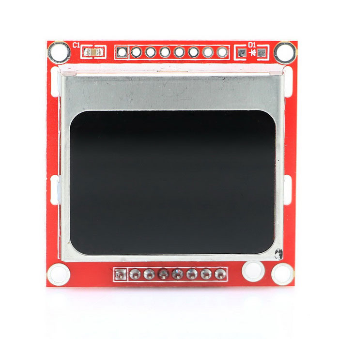
The Nokia 5110 display is basically a graphic LCD display useful for a lot of applications. It was intended originally to be used as a screen for cell phones and was used in lots of mobile phones during the 90’s. This display uses a low powered CMOS LCD controller/driver PCD8544, which drives the graphic display of size 84×48. It is very cheap and costs about 3$. You can get one here.
Nokia 5110 LCD
The Nokia 5110 LCD can display text, graphics as well as bitmaps. When this display is fully lit, it draws about 10mA but with the backlight off, it draws as low as 0.4mA. The power consumed by this display is very low compared to that of the keypad LCD shield used in the previous tutorial. I will be using the Arduino Mega for this tutorial as usual and you can buy one here. You can also buy jumpers, breadboards and power bank which you will be needing for this tutorial.
With the components acquired (links attached to the list), let’s wire them up.
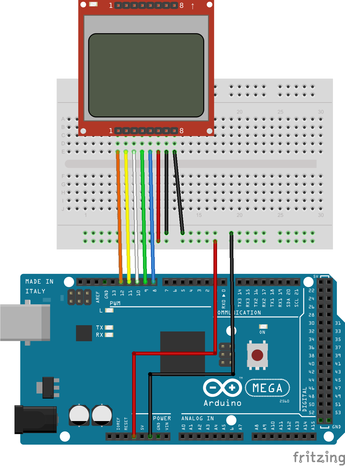
Schematic
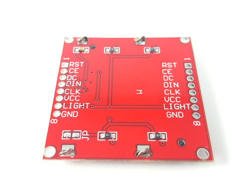
The display has two sides to which headers pins can be connected. You can pick one of the sides and solder header pins so that the display can fit firmly on the breadboard. The display works best when powered with 3.3 volts.
Nokia 5110 LCD Pin out
The light pin, when connected to ground turns the backlight “ON” while connecting it to VCC turns it “OFF”.
Now that we are done with the schematic, let’s move to the code for this project.
Code
Before we start writing the code for this project, first we need to download the 5110 LCD graph library that was made by rinky-dink electronics. The library does most of the heavy lifting and makes it easy for us o use the LCD. Click here to visit the download page and then download the LCD5110_graph zip file. When done, unzip the file to your preferred location and then rename the unzipped folder to something simple like “LCD5110”. Copy and paste this folder in your arduino library folder, then run your arduino IDE.
Click on the file, then on examples and then click on LCD5110. Since we are using the Arduino Mega, under the LCD5110 drop down click on Arduino (AVR) and the open up the LCD graph demo file.
Lets break up the code into bits and explain.
// It is assumed that the LCD module is connected to
// the following pins using a levelshifter to get the
// correct voltage to the module.
//      SCK  - Pin 8
//      MOSI - Pin 9
//      DC   - Pin 10
//      RST  - Pin 11
//      CS   - Pin 12
//
In the code we only have to change a few things. we can see from the comment section above that the RST pin of the display was connected to pin 11 but in our case we connected this pin to pin 12 of the Arduino Mega. We also have to change the CS from pin 12 to 11.
The first line after the comment section, the LCD5110 library was included and after that a myGLCD object was created with the numbers being the pins to which the LCD is connected. The last two values in the myGLCD object is the RST and CS values which has been changed as explained initially.
with this done, we move to the setup function. In the setup function, the InitLCD method is used to initialize the display and this method takes in a parameter for the display contrast. The contrast value is between 0-127 and since we didn’t pass in any value the default value which is 70 will be used. Next, the setFont method is called which sets smallFont as the display font style is called and lastly, the randomSeed function which is used to initialize the random number generator using analogRead on an unconnected pin as a random input.
In the loop function, on the first line the screen buffer is cleared using the clrScr method. The drawBitmap method was used to draw the arduino logo and this logo is placed in the screen buffer when the method is called. The update method is used to copy the screen buffer to the screen then we give it a delay of 2 seconds before clearing the screen buffer again.
myGLCD.clrScr();
myGLCD.drawBitmap(0, 0, arduino_logo, 84, 48);
myGLCD.update();
delay(2000);
myGLCD.clrScr();
myGLCD.print("LCD5110_Graph", CENTER, 0);
myGLCD.print("DEMO", CENTER, 20);
Next, a rectangle is drawn using the drawRect method. Lines are drawn in the for loop using the drawLine method which takes in four parameters (x1, y1, x2, y2). The font is changed to tiny font, then we print text on the screen and the update method is called to copy what’s in the string buffer to the screen. A delay of 5 seconds before clearing the screen is inserted.
Most of the functions used in the project have names that are self-explanatory like myGLCD.drawLine needs no explanation for instance as its clear the function draws a line.
Here is the full code for this project. Its an example from the Library named LCD5110_Graph_Demo and how to get to it has been described at the beginning of this section.
// LCD5110_Graph_Demo
// Copyright (C)2015 Rinky-Dink Electronics, Henning Karlsen. All right reserved
// web: http://www.RinkyDinkElectronics.com/
//
// This program is a demo of most of the functions
// in the library.
//
// This program requires a Nokia 5110 LCD module.
//
// It is assumed that the LCD module is connected to
// the following pins using a levelshifter to get the
// correct voltage to the module.
// SCK - Pin 8
// MOSI - Pin 9
// DC - Pin 10
// RST - Pin 11
// CS - Pin 12
//
#include <LCD5110_Graph.h>

LCD5110 myGLCD(8,9,10,12,11);
extern uint8_t SmallFont[];
extern uint8_t arduino_logo[];
extern unsigned char TinyFont[];
extern uint8_t The_End[];
extern uint8_t pacman1[];
extern uint8_t pacman2[];
extern uint8_t pacman3[];
extern uint8_t pill[];
float y;
uint8_t* bm;
int pacy;
void setup()
{
  myGLCD.InitLCD();
  myGLCD.setFont(SmallFont);
  randomSeed(analogRead(7));
}
void loop()
{
myGLCD.clrScr();
  myGLCD.drawBitmap(0, 0, arduino_logo, 84, 48);
  myGLCD.update();

  delay(2000);

  myGLCD.clrScr();
  myGLCD.print("LCD5110_Graph", CENTER, 0);
  myGLCD.print("DEMO", CENTER, 20);
myGLCD.drawRect(28, 18, 56, 28);
  for (int i=0; i<6; i++)
  {
    myGLCD.drawLine(57, 18+(i*2), 83-(i*3), 18+(i*2));
    myGLCD.drawLine((i*3), 28-(i*2), 28, 28-(i*2));
  }
  myGLCD.setFont(TinyFont);
  myGLCD.print("(C)2015 by", CENTER, 36);
  myGLCD.print("Henning Karlsen", CENTER, 42);
  myGLCD.update();

  delay(5000);

  myGLCD.clrScr();
for (int i=0; i<48; i+=2)
{
myGLCD.drawLine(0, i, 83, 47-i);
myGLCD.update();
}
for (int i=83; i>=0; i-=2)
{
myGLCD.drawLine(i, 0, 83-i, 47);
myGLCD.update();
}
delay(2000);
myGLCD.clrScr();
myGLCD.drawRect(0, 0, 83, 47);
for (int i=0; i<48; i+=4)
{
myGLCD.drawLine(0, i, i*1.75, 47);
myGLCD.update();
}
for (int i=0; i<48; i+=4)
{
myGLCD.drawLine(83, 47-i, 83-(i*1.75), 0);
myGLCD.update();
}
delay(2000);
myGLCD.clrScr();
for (int i=0; i<8; i++)
{
myGLCD.drawRoundRect(i*3, i*3, 83-(i*3), 47-(i*3));
myGLCD.update();
}
delay(2000);
myGLCD.clrScr();
for (int i=0; i<17; i++)
{
myGLCD.drawCircle(41, 23, i*3);
myGLCD.update();
}
delay(2000);
myGLCD.clrScr();
myGLCD.drawRect(0, 0, 83, 47);
myGLCD.drawLine(0, 23, 84, 23);
myGLCD.drawLine(41, 0, 41, 47);
for (int c=0; c<4; c++)
{
for (int i=0; i<84; i++)
{
y=i*0.017453292519943295769236907684886;
myGLCD.invPixel(i, (sin(y*6)*20)+23);
myGLCD.update();
delay(20);
}
}
delay(2000);
for (int pc=0; pc<3; pc++)
{
pacy=random(0, 28);
for (int i=-20; i<84; i++)
{
myGLCD.clrScr();
for (int p=4; p>((i+20)/20); p--)
myGLCD.drawBitmap(p*20-8, pacy+7, pill, 5, 5);
switch(((i+20)/3) % 4)
{
case 0: bm=pacman1;
break;
case 1: bm=pacman2;
break;
case 2: bm=pacman3;
break;
case 3: bm=pacman2;
break;
}
myGLCD.drawBitmap(i, pacy, bm, 20, 20);
myGLCD.update();
delay(25);
}
}
for (int i=0; i<25; i++)
{
myGLCD.clrScr();
myGLCD.drawBitmap(0, i-24, The_End, 84, 24);
myGLCD.update();
delay(100);
}
myGLCD.setFont(SmallFont);
myGLCD.print("Runtime (ms):", CENTER, 32);
myGLCD.printNumI(millis(), CENTER, 40);
myGLCD.update();
for (int i=0; i<5; i++)
{
myGLCD.invert(true);
delay(1000);
myGLCD.invert(false);
delay(1000);
}
}
Connect the board to your PC and make sure the right board and COM port are chosen. This can be done under the tools menu then Click on upload.
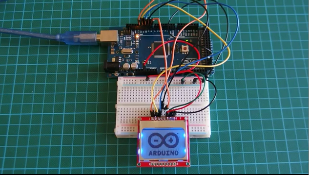
Demo
After uploading the code, you should see an output like the one shown in the image below.
Demo
Worked right? Yay!!!
See you next time. Don’t forget to leave your comments and questions.
The code is an example for the library so probably no need to attach here again.
You can watch a video tutorial of this topic here on youtube
AVR is a family of microcontrollers developed by Atmel beginning in 1996. These are modified Harvard architecture 8-bit RISC single-chip microcontrollers. The Atmel AVR core combines a rich instruction set with 32 general purpose working registers. Atmel’s ATmega8 comes from the AVR line of microcontroller and it is a gem of the modern maker movement. It is used as the heart of the first generation of the Arduino board to be widely adopted by electronics hobbyists. Countless creative projects are designed with those cheap yet powerful chips.
ATmega8 was originally developed in the early 1990s by two students at the Norwegian University of Science and Technology, Alf-Egil Bogen, and Vegard Wollan. Microcontrollers are different from microprocessors in terms of built-in memory and I/O peripherals. They typically have their own onboard program memory and RAM, rather than relying on external chips for these resources.
When Bogen and Wollan were in university, they faced trouble in following the steep learning curve of the complex instruction sets for microprocessors. Most of the processors used in those days were CISC(Complex instruction set computer) based. They wanted to design a RISC (reduced instruction set computer) based microcontroller with an aim in mind to create something that would be easy to program and relatively powerful. Bogen explained in a YouTube video,
I found them very hard to us. The learning curve to get to use them was hard; I found the development tools crappy. And also I saw that the performance of the products was not where I wanted it to be.
Alf-Egil Bogen – one of the creators of the AVR core
Computers, that are typically used on the day-to-day basis, use Von Neumann architecture. In this architecture, programs are loaded into the RAM first and then executed from the same. AVR uses the Harvardarchitecture, in which program memory and working RAM are kept separate, thus enables faster execution of instructions. The first prototype of AVR used ROM, which is not re-writeable, as the program memory. Later Atmel added easily programmable (and reprogrammable) flash memory to the processor core. The first commercial AVR chip, the AT90S8515, was released in 1996. Wollan says in a video,
instructions and stuff were things we were actually thinking of from the very beginning to make it efficient and easy to use from a high-level point of view
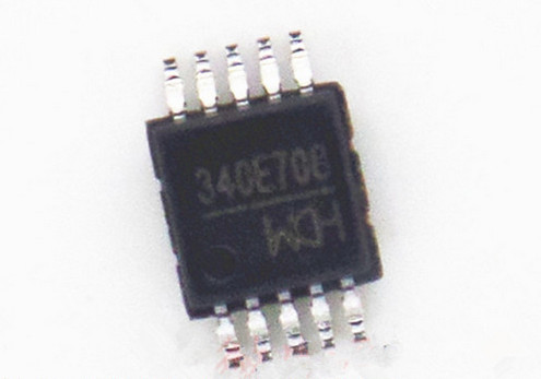
WCH, a Chinese integrated circuits manufacturer, has just released a new serial to USB chip called CH340E. Unlike other CH340 chips, it doesn’t require an external crystal and also needs less PCB space and BOM.
CH340 is a 3x3mm tiny chip comes in MSOP10 package and has 10 pins. Although it is smaller than other alternatives, it is a little more expensive than them. But considering other components and PCB size needed, the total cost of the BOM may be lower.
According to Electrodragon, it needs only two external parts to build a full function circuit. They also tested it with up to 150,000 baud rate to flash an ESP8266 chip. Most features and technical specifications are the some for CH340 family including CH340E, so the same drivers will work with it.
CH340E features
Full-speed USB device interface, compatible with USB V2.0.
Emulation standard serial port used to upgrade the original serial peripherals or add additional serial port via USB.
Computer applications under the Windows operating system serial port are fully compatible, without modification.
Hardware full duplex serial port, built-in send and receive buffer, support communication baud rate 50bps ~ 2Mbps.
Support common MODEM contact signal RTS, DTR, DCD, RI, DSR, CTS.
Through the additional level conversion device, providing RS232, RS485, RS422 and other interfaces.
Software compatible CH341, CH341 driver can be used directly.
Support 5V supply voltage and 3.3V supply voltage or even 3V supply voltage.
Built-in clock, no external crystal.
Available in SOP-16 and SSOP-20 and MSOP-10 lead – free packages, RoHS compliant.
The chip costs about 42 cents with a minimum order of 5 pieces on Eelectrodragon store. There is also an option to get a small board featuring the CH340E for about $1, and maybe cheaper in the future. Finally, the most powerful feature of this chip is that you can easily add USB connectivity to your own design.
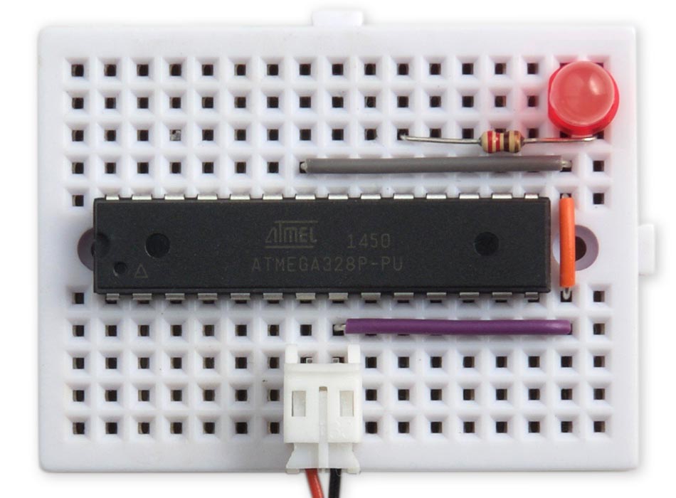
Here is another guide from David Johnson-Davies @ technoblogy.com explaining how to program an ATmega328 on a breadboard using the Arduino IDE. The guide is focused on how to use the internal clock of the microcontroller and how to achieve this using the Arduino environment. By default Arduino IDE doesn’t include a Boards option for an ATmega328 without an external crystal, so here is how to add this support.
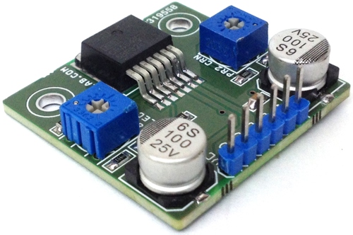
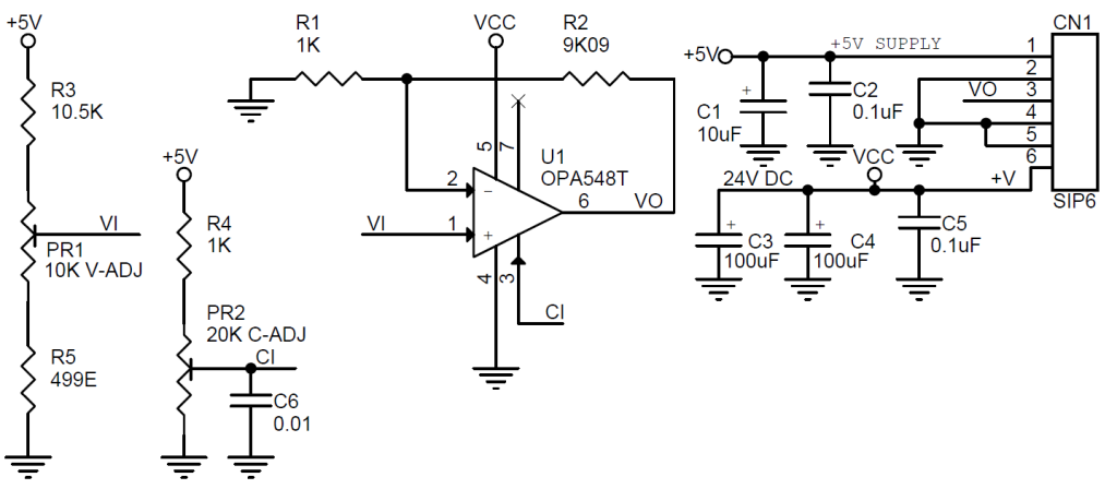
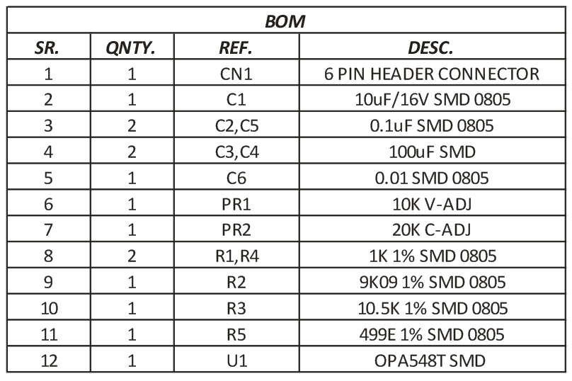
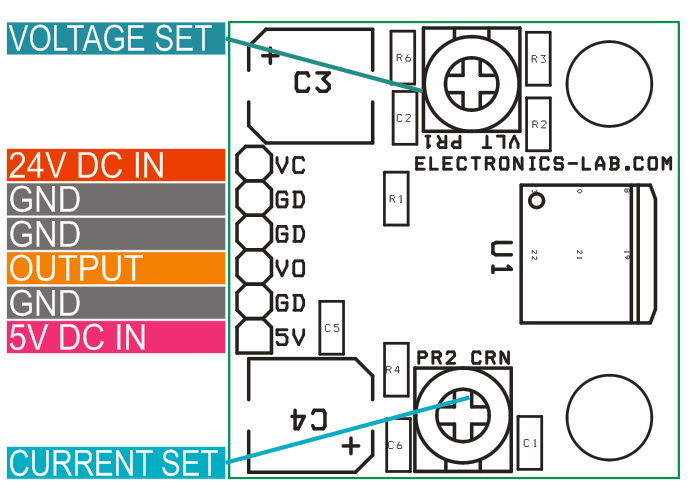
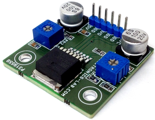
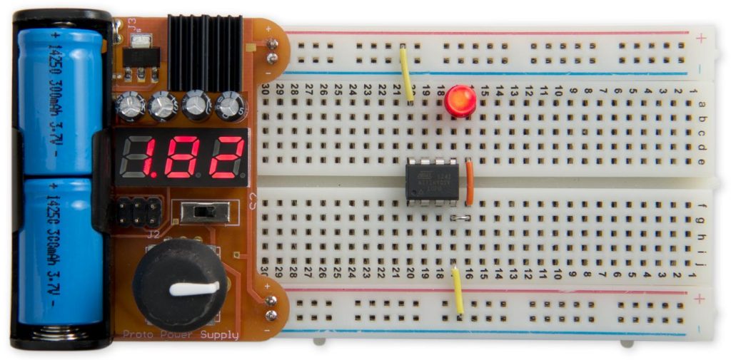
Project provides 1.2 to 20V DC output with current limiter adjustable to 0-5A. I have tested the circuit with 250mA output without a heat sink. Project is capable to drive 3A continues load and 5A peak, large size heat sink required for full load. The tiny power supply based on low cost OPA548 high-voltage and high-current operational amplifier is ideal for driving a wide variety of loads. The project provides excellent low-level signal accuracy and high-output voltage and current. The circuits operate with single supply 24V DC and logic supply 5V DC. The IC is internally protected against over-temperature condition and current overload. Trimmer potentiometer PR1 sets the output voltages, PR2 helps to set the current limit 0 to 5Amps.
Project provides 1.2 to 20V DC output with current limiter adjustable to 0-5A. I have tested the circuit with 250mA output without a heat sink. Project is capable to drive 3A continues load and 5A peak, large size heat sink required for full load. The tiny power supply based on low cost OPA548 high-voltage and high-current operational amplifier is ideal for driving a wide variety of loads. The project provides excellent low-level signal accuracy and high-output voltage and current. The circuits operate with single supply 24V DC and logic supply 5V DC. The IC is internally protected against over-temperature condition and current overload. Trimmer potentiometer PR1 sets the output voltages, PR2 helps to set the current limit 0 to 5Amps.
Note: Higher Out voltage 1.2V to 25V possible with input supplies 30V DC, replace capacitor C3, C4 for higher voltage.
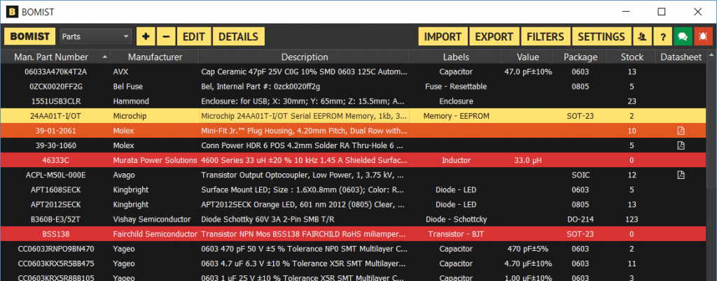
It all started a few years ago with Component Organizer, than BOMER and it’s now called BOMIST. The software runs locally, so no server nor setup required and you can have as many databases as you want (just run as many instances of BOMIST as you want). Additionally, it is integrated with Octopart, meaning you get plenty of useful real-time data: datasheets, descriptions, package names, values, prices as well as other useful information are automatically fetched online. Also, importing data into BOMIST is VERY easy which means you’ll get up and running in no time. BOMIST will keep improving, many new features are already inline and your feedback is always greatly appreciated. Give it a try, it’s FREE.
David Johnson-Davies @ technoblogy.com build a breadboard friendly power supply to power your Arduino or other low power electronics. The power supply is able to deliver 0V to 5.5V at up to 0.5A and it’s powered from two Li-Ion rechargeable batteries. The output can be adjusted using a rotary encoder, and the voltage is displayed on a three-digit 7-segment display. The whole circuit is controlled by an ATmega328.
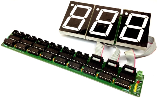
72 channels Serial (SPI) to parallel driver board has been designed for various applications. This project can be used as multi Solenoid driver, large size 7 segment display driver, bar graph driver, and LED driver. The project works with 5V logic levels. Output load supply 12V-48V DC and each output can drive 500mA load.
I have used 3 digits 2.3Inch 7 segment displays as an example, this board can handle up to 9 digits. The board can serve many applications like, Stop Watch, digital timer, counter, score board, token display and lot more.
Project built around 74HC595 and ULN2803 ICs, The 74HC595 devices contain an 8-bit serial-in, parallel-out shift register that feeds an 8-bit D-type storage register. The storage register has parallel 3-state outputs. Separate clocks are provided for both the shift and storage register.
72 Channels Serial To Parallel Driver Board Using 74HC595 & ULN2803 – [Link]