Arduino Weather Station with DHT11 and BMP180

Introduction

In the previous tutorial I showed you how to build a weather station using only the DHT11 sensor and I said the readings from this sensor is fairly accurate. In this tutorial, I will be using the DHT11 to measure only the humidity and BMP180 to measure pressure and temperature. That’s because its readings are more accurate than the DHT11 temperature readings.

Project Parts

I will be adding only the BMP180 sensor to the list in the previous tutorial.

1. BMP180 barometric pressure/temperature sensor.
2. DHT11 temperature and humidity sensor.
3. 16×2 LCD keypad shield.
4. Arduino Mega.
5. Breadboard.
6. Jumper wires.
7. Resistors.

The BMP180 is the new digital barometric pressure sensor from Bosch Sensortec, with a very high performance and it uses the I2C (pronounced I-squared- C or I-two- C) protocol. This digital sensor can measure barometric pressure, temperature and altitude.

BMP180

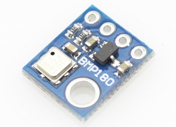
This sensor is a four pin device, the first pin is labelled VCC, second pin GND and the last two are the clock (SCL) and data (SDA) pins. You can purchase this sensor here.

The DHT11 is something we are familiar with, it has been used in couple of our tutorials here as a low cost temperature and humidity sensor that operates using the 1-wire protocol. It costs about $2 and you can get it here.

DHT11 Temperature and Humidity Sensor

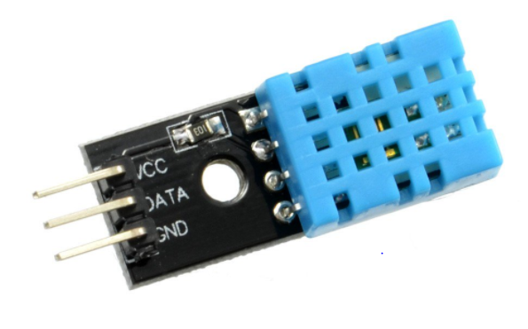
The readings from this sensor are fairly accurate, so we will be using this sensor to only measure humidity since the BMP180 gives more accurate temperature readings.

This sensor has three pins, the first which is the power pin VCC, next pin which is the middle one, which is the signal out or DATA pin and lastly the ground pin labelled GND.

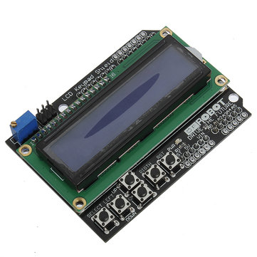
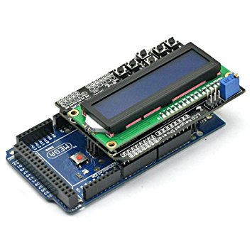
Yes, we will also be using the 16×2 LCD keypad shield as used in the previous tutorial. This shield makes connecting the 16×2 LCD module to any system quite easy, as it simply just plugs on the Arduino mega which is being used for this project. You can get this shield here.

LCD Keypad Shield

Schematics

Wire up your component as shown in the image below.
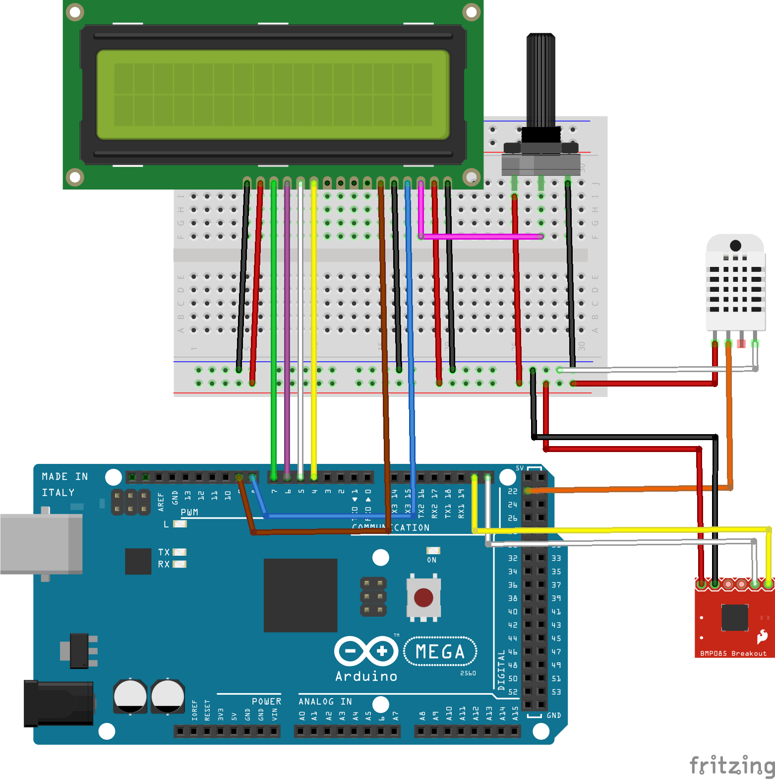
Schematics

LCD Connection

LCD - Arduino
Pin 1(VSS) - GND
Pin 2(VDD) - 5V
Pin 3(VO) - Potentiometer middle pin
Pin 4(RS) - D8
Pin 5(RW) - GND
Pin 6(E) - D9
Pin 7-10 - GND OR FLOAT
Pin 11 - D4
Pin 12 - D5
Pin 13 - D6
Pin 14 - D7
Pin 15 - 5V
Pin 16 - GND

Note that the RW pin is connected to GND because we will be writing only to the LCD and not to read from it, for this to be possible the RW pin has to be pulled LOW.

If you are Using the LCD shield it will look like the image below after mounting.

LCD Shield Mounted on the Arduino Mega


BMP180 Connection

The pin connection of the BMP180 is as illustrated below. The SCL pin of the sensor will go to the SCL pin on the Arduino Mega which is on pin 21. Likewise the SDA pin will go to the SDA pin of the Mega on pin 20.

BMP180 - Arduino
VCC - 5V
GND - GND
SCL – D21 (SCL)
SDA – D20 (SDA)

DHT11 Connection

Pin connection of the DHT11 to the arduino is as illustrated below. All DHT11 sensors have three main functional pins. The DHT types with four pins always have a void pin which is never connected to anything.

DHT11 – Arduino
VCC - 5V
DATA - D22
GND - GND

With our connections all done, its time to write the code for this project.

Code

Before writing the code, we need to download two libraries. One for the BMP180 which can be downloaded from github. Click on download zip and when done extract it. Open the extracted file and then go to software, double-click on Arduino and then on libraries. Rename the folder “SFE_BMP180” to something simpler like “BMP180”, copy this folder and paste it in your Arduino libraries folder.

If you followed the previous tutorial then you don’t need to download DHT11 library. If you don’t have the library you can download it from github.

When done extract it into Arduino libraries folder, then open Arduino IDE.

The first thing to be done is to include all the dependencies the code needs to run fine, libraries in this case.

#include "DHT.h"
#include <LiquidCrystal.h>
#include <SFE_BMP180.h>
#include <Wire.h>

Next, we create an object called pressure and also create a global variable temperature of type float.

SFE_BMP180 pressure;

float temperature;

Next, we define altitude in other to get the correct measurement of the barometric pressure and we enter the value in meters. it is 216.0 meters in Sparta, Greece. I also defined the DHT pin and the type.

#define ALTITUDE 216.0 // Altitude in Sparta, Greece

#define DHTPIN 22     // what pin we're connected to

#define DHTTYPE DHT11   

DHT dht(DHTPIN, DHTTYPE);

We create a DHT object and then pass in the pin number (DHTPIN) and the sensor type (DHTTYPE). The last line we create an LCD object, passing in the pin number our LCD pins are connected to as follows (lcd (RS, E, D4, D5, D6, D7)).

DHT dht(DHTPIN, DHTTYPE);
LiquidCrystal lcd(8,9,4,5,6,7);

In the setup function, we call the LCD begin method passing in the LCD size which is a 16×2. Next, we print on the first line of the LCD then call the DHT.begin() and the pressure.begin() methods.

void setup(void) {

  lcd.begin(16, 2);
  lcd.print("Reading sensors");
  dht.begin();
  pressure.begin();
}

In the loop function, the first line I created two variables “humidity” and “pressure” both of type int which will hold the humidity and pressure value.

float humidity, pressure;

The second line I added 10.0 to value got from the dht.readHumidity() method because I noticed my DHT11 sensor humidity value is off about 10 percent. In the third line, I called the function readPressureAndTemperatue() to read the pressure and temperature.

humidity = dht.readHumidity()+10.0f;
pressure = readPressureAndTemperature();

This function updates the global temperature variable and also returns the pressure value.
Next, in the loop function, I gave it a delay of two seconds after reading and then clear the LCD.

delay(2000);
 
lcd.clear();

Next we create three character arrays, two of size six and the last one of size 7. I used the dtostrf function to convert our temperature, humidity and pressure value from type float to string and then print it on the LCD. Note that the explicit typecasting used in the lcd.print() function ((char)223) is used to print the degree symbol on the display.

char tempF[6]; 
 char humF[6];
 char pressF[7];
 
 dtostrf(temperature, 5, 1, tempF);
 dtostrf(humidity, 2, 0, humF);
 dtostrf(pressure, 7, 2, pressF);

 //Printing Temperature
 lcd.print("T:"); 
 lcd.print(tempF);
 lcd.print((char)223);
 lcd.print("C ");

After getting the humidity, temperature and pressure we print it out on the LCD in a nicely formatted way.

//Printing Humidity
 lcd.print("H: ");
 lcd.print(humF);
 lcd.print("%");
 
 //Printing Pressure
 lcd.setCursor(0,1);
 lcd.print("P: ");
 lcd.print(pressF);
 lcd.print(" hPa");

Here is the complete code for this project.

#include "DHT.h"
#include <LiquidCrystal.h>
#include <SFE_BMP180.h>
#include <Wire.h>

SFE_BMP180 pressure;

float temperature;

#define ALTITUDE 216.0 // Altitude in Sparta, Greece

#define DHTPIN 22     // what pin we're connected to

#define DHTTYPE DHT11   

DHT dht(DHTPIN, DHTTYPE);
LiquidCrystal lcd(8,9,4,5,6,7); 

void setup(void) {

  lcd.begin(16, 2);
  lcd.print("Reading sensors");
  dht.begin();
  pressure.begin();
}

void loop() {
  
 float humidity, pressure;
  
 humidity = dht.readHumidity()+10.0f;
 pressure = readPressureAndTemperature();
 
 delay(2000);
 
 lcd.clear(); 
 
 char tempF[6]; 
 char humF[6];
 char pressF[7];
 
 dtostrf(temperature, 5, 1, tempF);
 dtostrf(humidity, 2, 0, humF);
 dtostrf(pressure, 7, 2, pressF);

 //Printing Temperature
 lcd.print("T:"); 
 lcd.print(tempF);
 lcd.print((char)223);
 lcd.print("C ");
 
 //Printing Humidity
 lcd.print("H: ");
 lcd.print(humF);
 lcd.print("%");
 
 //Printing Pressure
 lcd.setCursor(0,1);
 lcd.print("P: ");
 lcd.print(pressF);
 lcd.print(" hPa");
}

float readPressureAndTemperature()
{
  char status;
  double T,P,p0,a;

  status = pressure.startTemperature();
  if (status != 0)
  {
    delay(status);
    status = pressure.getTemperature(T);
    if (status != 0)
    { 
      temperature = T;
      status = pressure.startPressure(3);
      if (status != 0)
      {
        delay(status);
        status = pressure.getPressure(P,T);
        if (status != 0)
        {
          p0 = pressure.sealevel(P,ALTITUDE);       
          return p0;
        }
      }
    }
  }
}

Save your code, connect your Mega to your computer and make sure under your tools menu the board picked is “Arduino/Genuino Mega or Mega 2560” and also the right COM port is selected. Click upload when done.
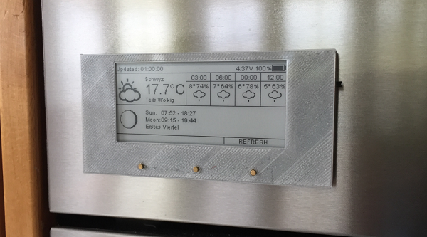
Demo

After uploading the code to your Arduino, You should see something like the Image shown below.

Demo

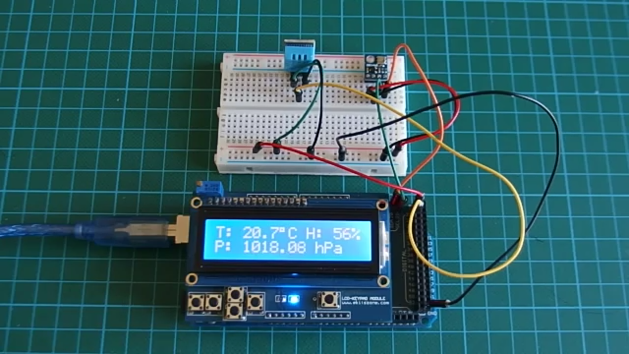
Worked right? Yea!!.

Visit here to download the code for this tutorial.

You can also watch a video tutorial on this topic on youtube.

20 Segment Jumbo Size SPI BarGraph Display

Jumbo 20 Segment SPI (Serial) bar graph driver using 74HC595 serial to parallel converter IC and BC635 display driver transistor. This project is useful for application like Amusement machines, arcade gaming, voltage display, current display, pressure sensor display, temperature sensor display , process control equipment, battery condition monitor and many more. Each segment of display consist 10 LED Bargraph display. It is easy to view from long distance, and easy to control by Micro-Controller.

20 Segment Jumbo Size SPI BarGraph Display – [Link]

20 Segment Jumbo Size SPI BarGraph Display

Jumbo 20 Segment SPI (Serial) bar graph driver using 74HC595 serial to parallel converter IC and BC635 display driver transistor. This project is useful for application like Amusement machines, arcade gaming, voltage display, current display, pressure sensor display, temperature sensor display , process control equipment, battery condition monitor and many more. Each segment of display consist 10 LED Bargraph display. It is easy to view from long distance, and easy to control by Micro-Controller.

Project built around 74HC595. The 74HC595 devices contain an 8-bit serial-in, parallel-out shift register that feeds an 8-bit D-type storage register. The storage register has parallel 3-state outputs. Separate clocks are provided for both the shift and storage register. The shift register has a direct overriding clear (SRCLR) input, serial (SER) input, and serial outputs for cascading. When the output-enable (OE) input is high, the outputs are in the high-impedance state. Both the shift register clock (SRCLK) and storage register clock (RCLK) are positive-edge triggered. If both clocks are connected together, the shift register always is one clock pulse ahead of the storage register. All 8 parallel output are connected to inputs of BC635 Transistor which drive the display segment. Resistor used in series of the display for current control, each display draw 90mA current. The project works with 12V DC supply, onboard regulator helps to provide 5V to 74HC595. CN1 SPI data input and CN2 12V DC supply in. CN1:- PIN 1= 5 DC Output, PIN 2= Serial Data In, PIN 3= RCLK, PIN 4=SRCLK, PIN 5=GND

Specifications

  • Supply 12V 2A

Schematic

Parts List

Photos

Video

Acusis – array microphone for speech recognition

An echo-canceling, far-field, linear array microphone for speech recognition and voice communications.

Acusis is a simple-to-use, complete solution for improving the audio quality for your speech recognition or video communications project. It solves multiple audio issues in a single device that mounts on a TV or monitor and hooks up to your Mac, PC, or single-board computer with standard USB protocols.

Acusis – array microphone for speech recognition – [Link]

Spinduino – IoT Fidget Spinner

IoT Fidget Spinner with Bluetooth Low Energy and POV LED Display by Uri Shaked.

A smart, programable Fidget Spinner with the following features:

  • JavaScript programmable
  • 10-Pixel RGB PoV display (using APA102 LEDs)
  • Spin count / speed detection using a magnetic latch
  • Using Nordic Semiconductor nRF52832 chip
  • Bluetooth Low Energy (BLE) communication with smart phone / computer for controlling the display, reading the spin count and programming
  • Over-the-air firmware upgrades
  • Fully open-source

Spinduino – IoT Fidget Spinner – [Link]

4-port NanoHub – tiny USB hub for hacking projects

Muxtronics @ tindie.com sells their 4-port NanoHub board:

The NanoHub 4-port is a natural evolution of the original 2-port NanoHub – a truly tiny USB hub to use in the most cramped of spaces. Nanohub 4-port is bigger and better! Even though it boasts twice as many downstream ports (effectively tripling its usefulness; providing 3 extra USB ports instead of just 1), it is only 4mm wider (1/8″). Also, by popular request, ESD protection diodes are included on the input and output ports, meaning you can safely use the NanoHub 4-port with user-accessible ports, where you might zap the port contacts with static electricity. Lastly, the power traces have gotten a slight boost; you can now draw up to 4A on the output ports (combined, sustained).

4-port NanoHub – tiny USB hub for hacking projects – [Link]

ESP8266 based e-paper WiFi weather station

Erich Styger documented his experience building Daniel Eichhorn’s e-paper weather station with a custom enclosure:

Using e-paper for a weather station is an ideal solution, as the data does not need to be updated often. By default, the station reaches out every 20 minutes for new data over WiFi and then updates the display. Daniel Eichhorn already has published kits for OLED (see “WiFi OLED Mini Weather Station with ESP8266“) and touch display (see “WiFi TFT Touch LCD Weather Station with ESP8266“). I like them both, but especially the TFT one is very power-hungry and not really designed to work from batteries. What I would like is a station which can run for weeks.

ESP8266 based e-paper WiFi weather station – [Link]

STMicro Introduces 20 Cents MCU in 8-Pin Package

STMicro has launched STM8S001J3, a new 8-bit micro-controller that sells for $0.20 per unit in 10k quantities. STM8S001J3 is also the first STM8 MCU offered in 8-pin package (SO8N), and should compete with some of the Microchip Attiny or PIC12F series micro-controllers.

STM8S001J3 has small package and little number of pins, but still it embeds rich set of peripherals. Below some of key features of this device:

  • Core and system
    • Flexible clock control capable to use three clock sources: 2 internal (HSI 16MHz, LSI 128kHz), 1 external clock input.
    • Wide operating voltage range: from 2.95V to 5.5V
    • 5 I/Os
    • 8- and 16-bit timers
  • Memories
    • 8k Flash
    • 1k RAM
    • 128 Bytes EEPROM
  • Conenctivity and debug
    • UART
    • SPI
    • I2C
    • Single Wire Interface Module
  • Analog
    • 10-bit ADC with 3 channels

Nerdonic Atom X1 is the World’s Smallest 32-bit Arduino Compatible Board

Tiny 32-bit Dev Board. 14.9mm², Breadboard, 0.95g, 3-20V input, I²C, 8 PWM, Serial, 6 ADC, Prog LED.

There is a new board in the ecosystem which claims to be the world’s smallest 32-bit Arduino board. The name of it Atom X1 and measures 14.9×14.9 mm.

Atom X1 specifications:

  • MCU – Microchip Atmel  SAMD21 Cortex M0+ MCU @ 48 MHz with 256KB flash, 32KB SRAM
  • I/Os via 2x 5-pin 2.54mm pitch headers
    • Up to 8x digital I/O
    • Up to 8x PWM
    • Up to 6x analog (ADC)
    • 1x UART
    • 1x I2C
    • 1x reset
    • Limits – 3.7V, 7mA
  • USB – 1x micro USB port
  • Programming – via micro USB port or SWD header
  • Misc – Power LED, user LED, button
  • Power Supply
    • 3.3-20V (regulated to 3.3v) via power Pin 1
    • 3.3V via power pin 2
    • 5V (regulated to 3.3v) via Micro USB port
    • Current Draw Atom X1 = ~10mA
  • Dimensions – 14.9 x 14.9 x 4.4mm
  • Weight – 0.95 grams

The board is breadboard compatible, pre-flashed with Arduino Zero bootloader, and can be programmed in the Arduino IDE just like the original board.

The project has been launched on Indiegogo. Early bird rewards start at 10 GBP (~$13.2 US) for the board with shipping adding 2 GBP to the UK, and 7 GBP to the rest of the world. Delivery is scheduled for December 2017.

Rigol general-purpose 200MHz scopes from under €600

RIGOL Technologies introduces its new DS2000E Series Oscilloscope, a 200MHz, 2 channel scope that continues RIGOL‘s tradition of combining unmatched capabilities at unprecedented price points to transform the test and measurement industry.

The DS2000E is available at either 100MHz or 200MHz bandwidths.  All models provide 2 analog channels with 50 Ω input impedance standard.  With real-time sample rate of 1GS/Sec (on both channels), memory depth of up to 28Mpts standard, and waveform capture rate up to 50,000 wfms/sec, the DS2000E provides the raw instrument performance required to meet today’s more advanced debug challenges.  When coupled with the large 8 inch WVGA intensity graded display, complete network connectivity, hardware waveform record/playback, serial trigger and decode, and other advanced analysis capabilities, starting at just $647, engineers and technicians will see RIGOL has again transformed the price performance assumptions in the Basic Oscilloscope Market.

Rigol general-purpose 200MHz scopes from under €600 – [Link]

TOP PCB Companies