Bosch BME280 sensor combines pressure, humidity and temperature measurement

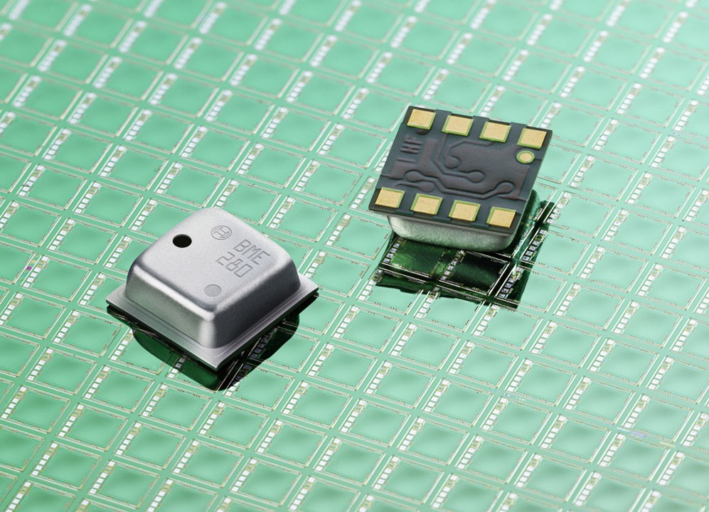
Bosch Sensortec announces a world first in sensor technology: the BME280 Integrated Environmental Unit combines sensors for pressure, humidity and temperature in a single package. This unique sensor has been developed to support a broad range of emerging high performance applications such as indoor navigation, home automation control, personalized weather stations and innovative sport and fitness applications. The precise altitude measurement function of the BME280 is a key requirement in applications such as indoor navigation with floor tracking where exceptional accuracy, low temperature drift and high resolution are needed. Additionally, the BME280 has a best-in-class response time of just one second for humidity determination, excellent ambient temperature measurement and low energy consumption.

More precise measurement at lowest power consumption

With a small footprint of just 2.5 x 2.5 mm2and a height of 0.93 mm in a space-saving 8-pin LGA package, the sensor offers high design flexibility and is ideally suited for mobile devices with limited space such as smartphones, tablets, smart watches and electronic wristbands. Very low current consumption of only 3.6 µA (at 1 Hz) makes the BME280 Integrated Environmental Unit particularly suitable for battery-driven applications. Three power modes and separately configurable oversampling rates for pressure and temperature measurements allow designers to adapt the BME280 to a wide range of use cases.

The humidity sensor within the Integrated Environmental Unit measures relative humidity (0% to 100%) across a wide temperature range from -40°C to +85°C with a fast response time of less than 1 second. The humidity measurement accuracy is ±3% with a hysteresis of 2% or better, and the temperature reading accuracy is within 0.5°C.

more details on the Bosch Press Release.

Three Ways to Make Arduino Works As A USB/TTL Converter

Even if you have years working with electronics, you will still find some simple hacks that you never thought about before. Personally and to save money, when I was a student with a very limited budget I knew that my Arduino UNO can work as a USB/TTL(serial) converter. I used to remove the Atmega328P from my Arduino UNO R3 board in order to use the board as a converter not as a development board.

Why we need to do some tweaking to Arduino in order to use 0 and 1 pins for direct USB <-> UART conversion? This is because of what’s called fan-out (fan-out of a logic gate output is the number of gate inputs it can drive). In Arduino UNO case, the RX & TX lines (pins 0 and 1) are connected to FT232RL/Atmega8U2 USB to TTL bridge and to the Atmega328P MCU (check the schematic). So using the same pins with an external connections without doing any changes to Arduino UNO board probably won’t work.

Patel Darshil over Hackster.io listed three ways to make Arduino works as a USB/TTL converter:

Hack #1: Set Pin 0&1 Mode to Input Mode

This is done using code:

Pin Mode Set Arduino

But why this solves the problem? Well, GPIO can operate in two modes, input and output. In the input mode the equivalent impedance of the pin is too high; therefore, the Arduino/Atmega328P’s pins will have almost no electrical effect to the converter RX/TX pins.

Hack #2: Keep Atmega in Reset Mode

Just connect the RES pin with GND (the bold red wire in the image bellow)

Arduino Reset
Image Courtesy of Patel Darshil

GPIOs are configured using special registers. For example, Atmega has GPIO port data direction register (DDR) to set the GPIO as an input or an output for each port. The value of this register is cleared during reset. Therefore, the MCU’s GPIOs mode will be input. This means high impedance, subsequently.

Hack #3: Remove The MCU

This is the common way used by most Arduino UNO users, but it’s not applicable when it comes to new versions of Arduino; where, the MCU is SMD and can’t be removed.

A New Soundproof Air-Transparent Window

Imagine you have a window that isolates noises and passes only nature sounds like sea waves in addition to fresh air. Seems like it will happen in dreams only, right? Actually, researchers from South Korea, bring this window from dreams to the real.

Soundproofing is difficult and expensive, it usually relies on transferring sound into a medium which absorbs and attenuates it. But this also will stop the airflow. Sang-Hoon Kima and Seong-Hyun Lee have successfully build a new window that allows airflow to pass without sound and noises.

The new design is simple and depends on two acoustic conditions, strong diffraction and negative bulk modulus.

Strong Diffraction

At first, this method makes the sound waves diffused into a customized resonator called diffraction resonator. This resonator maximizes the diffraction impact with its air hole in the center of the body. In addition, the diameter of the hole will control the range of frequencies to restrict. Only waves with a wavelength smaller than the diameter can pass through the hole.

Artificial atoms of diffraction resonators. Diameters of the air holes: 20mm for (a1), (a2), and (a3), and 50mm for (b1), (b2), and (b3). There are three structures: one room for (a1) and (b1), two rooms for (a2) and (b2), and four rooms for (a3) and (b3).

Negative Bulk Modulus

A material’s bulk modulus means its resistance to compression. It is also an important factor in determining the speed at which sound moves through it. So, a material with a negative bulk modulus exponentially attenuates any sound passing through it.

While it is hard to find a solid material having a negative bulk modulus, Kima and Lee have designed a new sound resonance chamber. This chamber consists of two parallel transparent acrylic plastic plates. The efficiency of the double-glazed window is measured by getting the sound into the chamber. To maximize the efficiency, they drilled a hole through each plate. This double-glazing window has also used as a building block to make windows in larger sizes.

Designs of the medium-sound separator. 20mm (left) and 50mm (right). It is composed of the three kinds of artificial atoms which are connected in series and parallel.

There are several applications of this windows, changing the size of the holes makes the windows tunable for certain frequencies. To know more about this research review this paper.

Voladd: The First Fully Integrated 3D Printer

The Spain based Voladd company introduces their fully integrated 3D printer on a kickstarter campaign. The heart of printer is a BeagleBone Black single board computer running Debian Linux that connects to cloud service directly without need of an attached computer.

With your smartphone, tablet or laptop, you have the power to search for thousands of available objects in the online platform connected to your Voladd 3D printer. It’s as easy as pressing play and listening to a song. No downloads. No software installation. No previous knowledge of 3D printing required. Just select your desired object and make it. It’s as simple as that.

Kickstarter pricing starts with early bird packages of 499 Euros ($591), with shipments due in December.

Researchers Developed Low Cost Battery From Graphite Waste

Lithium-ion batteries are flammable and the price of the raw material is increasing. Scientists and engineers have been trying to find out a safe yet efficient alternative to the Lithium-ion technology. The researchers of Empa and ETH Zürich have discovered promising approaches as to how we might produce powerful batteries out of waste graphite and scrap metal.

Kostiantyn Kravchyk and Maksym Kovalenko, the two chief researchers of the Empa’s Laboratory for Thin Films and Photovoltaics, led the research group. Their ambitious goal is to make a battery out of the most common elements in the Earth’s crust – such as graphite or aluminum. These metals offer a high degree of safety, even if the anode is made of pure metal. This also enables the assembly of the batteries in a very simple and inexpensive way.

In typical lithium-ion battery design, the negative electrode or anode is made from graphite. This new design, however, uses graphite as the positive electrode or cathode. In order to make such batteries run, the liquid electrolyte needs to consist of special ions that form a kind of melt and do not crystallize at room temperature. The metal ions move back and forth between the cathode and the anode in this “cold melt”, encased in a thick covering of chloride ions.

Alternatively, large but lightweight and metal-free organic anions could be used. But, this raises some questions which cannot be solved easily – where are these “large” ions supposed to go when the battery is charged? What could be a suited cathode material? In comparison, the cathode of the lithium-ion battery is made of a metal oxide which can easily absorb the small lithium cations during charging. This does not work for such large organic ions.

To solve the problem, Kovalenko’s team came up with a unique and tricky solution: the researchers turned the principle of the lithium-ion battery upside down. In Kovalenko’s battery, the graphite is used as a cathode; i.e., the positive pole. The thick anions are deposited in the intermediate spaces in the graphite. While searching for the “right” graphite, they found that waste graphite produced in steel production (known as kish graphite) works the best as a cathode material. Natural graphite is suitable when it is in the form of coarse flakes and not too finely ground.

Sensor board for micro:bit

The MonkMakes Sensor Board for micro:bit allows you to sense sound level, temperature and light level.

Features

  • 3V and GND connections can be made from either side and allow you to power a second board such as the MonkMakes Relay Board or MonkMakes Speaker.
  • LED ‘power on’ indicator
  • Reverse polarity protection
  • All three sensors are analog and can be connected to pins P0, P1 and P2 using alligator clips.

Sensor board for micro:bit – [Link]

SprintIR6S, World’s Fastest NDIR CO2 Sensor

Gas Sensing Solutions (GSS) Ltd is a designer and manufacturer of low power, high speed Non-Dispersive Infrared (NDIR) carbon dioxide gas sensors. Recently, it has claimed a new speed record for its SprintIR6S NDIR CO2 sensor.

The new sensor comes with response rates that had never been reached before by any other NDIR CO2 sensors. It can take up to 20 readings per second, and has a six-times faster response rate than the current SprintIR.

According to Ralph Weir, GSS’ CEO, the sensor uses LEDs and photodiodes to measure differential light absorption between light at 4.2 and 4.4 μm. So, they succeeded to develop ultra-speed sensor, while other detectors take several seconds or even minutes to take a reading.

“Our LEDs, by contrast, are Solid State emitters, and illuminate almost instantly. With the new SprintIR6S, we’ve also minimised the sample volume down to only 2ml, which enables us to achieve our fastest ever response rates.”
~ Ralph Weir

The SprintIR6S is less than a cubic inch in dimension with 23.8mm in diameter and 24mm tall. It operates at a range between 3.25V and 5.5V and consumes only 35mW. SprintIR6S is also available in measurements ranges from 0% to 100%.

Main Specifications of SprintIR6S

  • Warm-up Time: < 30 seconds
  • Operating Conditions:
    • 0°C to 50°C (Standard)
    • 0 to 95% RH, non-condensing
  • Recommended Storage: -30°C to +70°C
  • Sensing Method:
    • Non-dispersive infrared (NDIR) absorption
    • Patented Gold-plated optics
    • Solid-state source and detector
  • Sample Method: Flow through
  • Measurement Range: 0-5%, 0-20%, 0-100%
  • Accuracy: ±70 ppm +/- 5% of reading (100% Range ±300 ppm +/-5% of reading)
  • Non Linearity: < 1% of FS
  • Pressure Dependence: 0.13% of reading per mm Hg in normal atmospheric conditions
  • Operating Pressure Range: Atmospheric pressure range. Lower and higher pressures require more advanced pressure compensation.
  • Response Time: Flow Rate Dependent – see graph below. Response time also depends on user configurable digital filter settings.
  • Power Input:
    • 3.25 to 5.5V. (3.3V recommended).
    • Peak Current 33mA.
    • Average Current <12mA.

Applications of SprintIR6S are those which require capture of rapidly changing CO2 concentrations. Such as capnography, fitness testing, metabolic assessment, sports science, veterinary medicine, bio-medical, and incubators.

For more information and detailed specification, you can download the datasheet, or contact GSS to order or for more information.

2018 Will Mark A Milestone in GNSS Technology with 30-centimeter Accuracy

You’re in a crowded street with many high buildings around you and you find your car position on Google maps is wrong. That’s usual, right? This is caused from (fake/distorted) GPS signals reflected from the high buildings around you which make your GPS receiver do some wrong calculations. So be careful don’t always listen to what GPS assistant says!

GPS MEMES

Even with no wrong calculations, the current GPS accuracy is about 5 meters, but this is going to change in next year 2018; where, a new set of satellites with enhanced GPS signals will be available for public use.

The enhanced GPS signal can make the GPS receivers do position calculations with 30-centimeter accuracy instead of today’s 5 meters. Moreover, it solves the problem of reflections inside crowded area with buildings with narrow window to the sky.

The global navigation satellite systems: Europe’s Galileo, Russia’s Glonass, China’s Beidou and US’s GPS transmits information about its position, the current time and more. The receiver, then, uses these signals to calculate the distance from each satellite based on how long the messages took to arrive. However, knowing the distance from 3 satellites is enough to calculate the position using geometric process called trilateration. This message broadcasted by a satellite called L1 signal. where, L band is a range of frequencies from 1 to 2 gigahertz.

To know more about navigation message data structure on L1, read this guide (page 19).

How trilateration works in GPS
How trilateration works. Image Courtesy of Tim Gunther, National Geographic

The next generation set of satellite will broadcast, in addition to L1 signal, a higher frequency signal called L5; where, GPS signal carriers are in the L band and are centered at 1176.45 MHz for L5 and 1575.42 MHz for L1. The following image is going to explain why the new signal can solve the old problem of reflections.

How L5 GPS signal helps
Image Courtesy of Broadcom

Silicon chips market and specifically Broadcom provides BCM47755, the first chipBCM47755 that support the new generation GPS. However, BCM47755 seems interesting not only as a GPS receiver only but also as a sensors hub, where the new chip has 2 cores inside, ARM-based 32-bit Cortex-M4F (CM4), an ARM-based Cortex-M0 (CM0), to implement the ARM big.LITTLE architecture which considered as a new battery-saving method consist of slow processor cores (LITTLE) with relatively more powerful and power-hungry ones (big).

BCM47755 supports GPS,GLONASS, BeiDou (BDS), Galileo(GAL), and SBAS satellite systems and has an operating frequency 150 MHz for Cortex-M4F and 75 MHz for Cortex-M0 CPU. Regarding the peripherals, the new chip provides a set of features like any other off-the-shelf MCU:

  • Up to 50 programmable GPIOs.
  • 2 channel ADC with 12 bit resolution.
  • Flexible interfaces including:  3 SPI ports, four UART ports and four I2C ports.
  • 4 different timers.

Finally, the new chip is available in 77-pin WLBGA package.

To read more about the new GPS generation, check IEEE’s report.

50V – 10A Bidirectional DC Motor Driver Using A3941

This tiny board designed to drive bidirectional DC brushed motor of large current. DC supply is up to 50V DC. A3941 gate driver IC and 4X N Channel Mosfet IRLR024 used as H-Bridge. The project can handle a load up to 10Amps. Screw terminals provided to connect load and load supply, 9 Pin header connector provided for easy interface with micro-controller. On board shunt resistor provides current feedback.

The A3941 is a full-bridge controller for use with external N-channel power MOSFETs and is specifically designed for automotive applications with high-power inductive loads, such as brush DC motors. A unique charge pump regulator provides full (>10 V) gate drive for battery voltages down to 7 V and allows the A3941 to operate with a reduced gate drive, down to 5.5 V. A bootstrap capacitor is used to provide the above-battery supply voltage required for N-channel MOSFETs. An internal charge pump for the high-side drive allows DC (100% duty cycle) operation.

50V – 10A Bidirectional DC Motor Driver Using A3941 – [Link]

50V – 10A Bidirectional DC Motor Driver Using A3941

This tiny board is designed to drive a bidirectional DC brushed motor of large current. DC supply is up to 50V DC. A3941 gate driver IC and 4X N Channel Mosfet IRLR024 used as H-Bridge. The project can handle a load of up to 10A. Screw terminals are provided to connect the load and load supply, and 9 Pin header connector is provided for easy interface with the microcontroller. An on board, shunt resistor provides current feedback.

The A3941 is a full-bridge controller for use with external N-channel power MOSFETs and is specifically designed for automotive applications with high-power inductive loads, such as brush DC motors. A unique charge pump regulator provides full (>10 V) gate drive for battery voltages down to 7 V and allows the A3941 to operate with a reduced gate drive, down to 5.5 V. A bootstrap capacitor is used to provide the above-battery supply voltage required for N-channel MOSFETs. An internal charge pump for the high-side drive allows DC (100% duty cycle) operation.

The full bridge can be driven in fast or slow decay modes using diode or synchronous rectification. In the slow decay mode, current recirculation can be through the high-side or the low side FETs. The power FETs are protected from shoot-through by resistor R7 adjustable dead time. Integrated diagnostics provide an indication of under voltage, over temperature, and power bridge faults, and can be configured to protect the power MOSFETs under most short circuit conditions.

The A3941 is a full-bridge MOSFET driver (pre-driver) requiring a single unregulated supply of 7 to 50 V. It includes an integrated 5 V logic supply regulator. The four high current gate drives are capable of driving a wide range of N-channel power MOSFETs, and are configured as two high-side drives and two low-side drives. The A3941 provides all the necessary circuits to ensure that the gate-source voltage of both high-side and low-side external FETs are above 10 V, at supply voltages down to 7 V. For extreme battery voltage drop conditions, correct functional operation is guaranteed at supply voltages down to 5.5 V, but with a reduced gate drive voltage. The A3941 can be driven with a single PWM input from a Microcontroller and can be configured for fast or slow decay. Fast decay can provide four-quadrant motor control, while slow decay is suitable for two-quadrant motor control or simple inductive loads. In slow decay, current recirculation can be through the high-side or the low-side MOSFETs. In either case, bridge efficiency can be enhanced by synchronous rectification. Cross conduction (shoot through) in the external bridge is avoided by an adjustable dead time. A low-power sleep mode allows the A3941, the power bridge, and the load to remain connected to a vehicle battery supply without the need for an additional supply switch. The A3941 includes a number of protection features against under voltage, over temperature, and Power Bridge faults. Fault states enable responses by the device or by the external controller, depending on the fault condition and logic settings. Two fault flag outputs, FF1 and FF2, are provided to signal detected faults to an external controller.

Features

  • High current gate drive for N-channel MOSFET full bridge
  • High-side or low-side PWM switching
  • Charge pump for low supply voltage operation
  • Top-off charge pump for 100% PWM
  • Cross-conduction protection with adjustable dead time
  • 5 to 50 V supply voltage range
  • Integrated 5 V regulator
  • Diagnostics output
  • Low current sleep mode

Schematic

Parts List

Connections


Truth Table

Photos

TOP PCB Companies