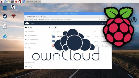
Install OwnCloud on Raspberry Pi And make your own cloud server.
OwnCloud set on Raspberry Pi can be a good example of smart cloud storage. A cloud storage is a cloud computing model in which the data is stored on remote servers and maintained by a cloud storage service provider. This allows users to customize their data and share it with friends and business partners over the Internet.
OwnCloud as cloud storage server is a great opportunity, especially for those who would like to use OwnCloud on Raspberry Pi (or any other ARM device).
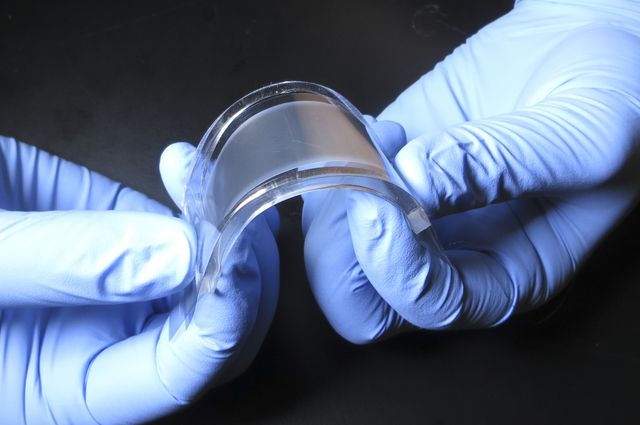
Engineers and scientists from the UCLA Henry Samueli School of Engineering and Applied Science and SRI International, California, have created a thin flexible device that could keep smartphones and laptop computers cool and prevent overheating. The component is based on the electrocaloric effect – a phenomenon where the temperature of material changes when an electric field is applied to it. The research has been published in Science.
Thin, flexible cooling device
The system’s flexibility also allows it to be used in wearable electronics, robotic systems, and new types of personalized cooling systems. It is the first demonstration of a solid-state cooling device based on the electrocaloric effect. The method devised by UCLA and SRI researchers is very energy-efficient. It uses a thin polymer film that transfers heat from the heat source – a battery or a processor – to a heat sink, and alternates contact between the two by switching on and off the electric voltage.
Because the polymer film is very flexible, the system can be used in devices with complex shapes or moving surfaces. Body tracking wearable devices can easily accommodate this flexible cooling device. Such cooling pad could keep a person comfortable in a hot office and thus lower the electricity consumption for air conditioning. Or it could be placed in a shoe to keep a runner comfortable while running in the sun. It’s like a personal air conditioner.
The tendency of flexible electronics to overheat remains a major challenge for engineers. The cooling systems in larger devices like air conditioners and refrigerators, which use vapor compression, are just too large for mobile electronics. The new cooling device produces a specific cooling power of 2.8 watts per gram and a COP of 13. This is more efficient and compact than the existing surface-mountable solid-state cooling technologies, opening a path to using the technology for a variety of practical applications.
Roy Kornbluh, an SRI research engineer, said,
The development of practical efficient cooling systems that do not use chemical coolants that are potent greenhouse gases is becoming even more important as developing nations increase their use of air conditioning.
Welcome to another Arduino Tutorial! Today we are going to learn how to use Bluetooth to exchange data between two Arduino boards! As a demonstration project, we are going to build a simple weather station. There is a lot to cover so let’s get started!
Arduino Two-Way Bluetooth Communication Tutorial – [Link]
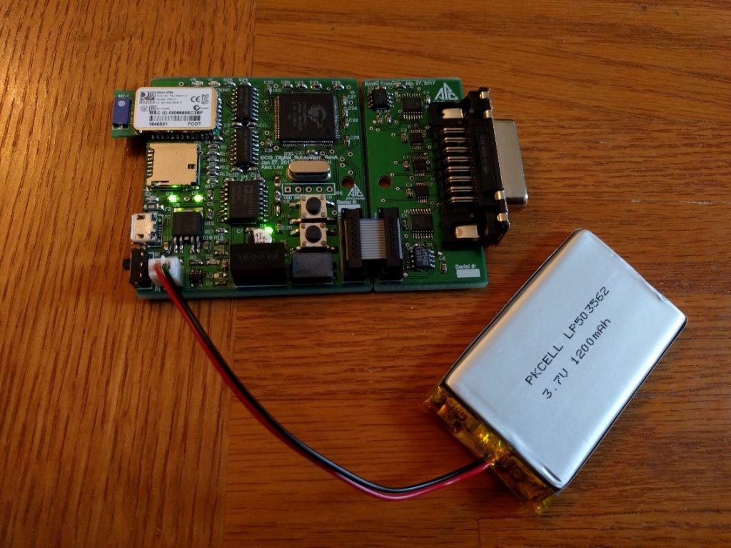
During the academic year of 2016-2017 at McMaster University, in conjunction with Dr. DeBruin, Christina Riczu, Thomas Phan and Emilie Corcoran, we developed a compact, battery powered, 12-lead electro-cardiogram. The project won 1st place in the biomedical category at the ECE Capstone Poster Day.
Design and Implementation of a 12 Lead Portable ECG – [Link]
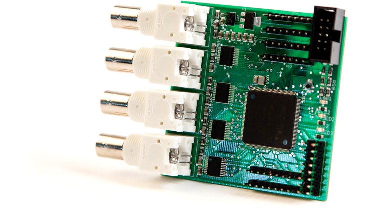
Haasoscope is the first open-source, open-hardware, flexible, small, cheap, oscilloscope and data-acquisition board. You can use the stock firmware for basic oscilloscope functionality, or modify the firmware to customize what the Haasoscope does.
Preliminary features and specifications:
4 x 100 MHz, 8-bit ADC channels with BNC cable inputs
Altera Max10 FPGA with 8k logic elements and 387kb of memory
Reprogram firmware over JTAG, or on the fly, with free Quartus II software
Readout over serial-to-USB at 1.5 Mb/s, about 20 Hz for 4 channels of 512 samples each
USB powered, (or other 5 V input, switchable), ~1.2 Watt
8 x spare digital I/O
9 x additional analog I/O with 1 MHz (1MSPS combined) at 12 bits
7 x programmable LEDs, and a reset button
Haasoscope – Cheap, flexible, data acquisition for all! – [Link]
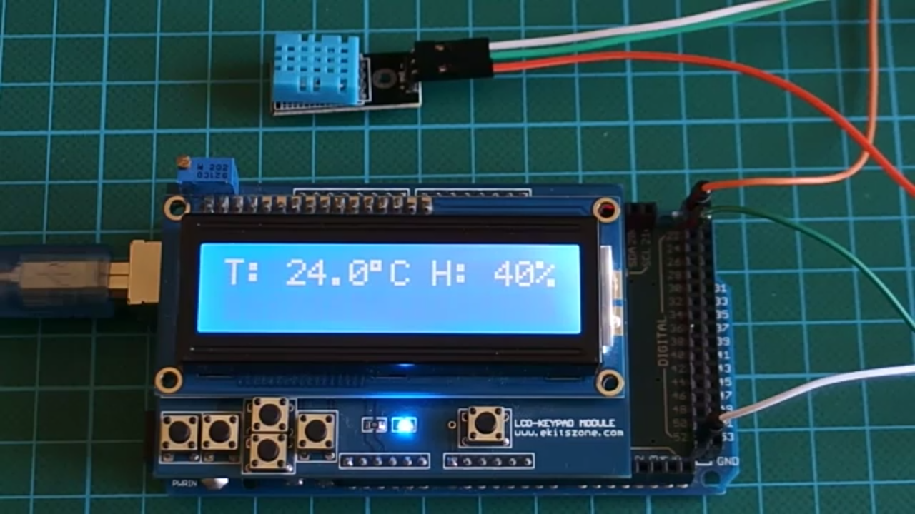
Using a display to view the temperature and humidity of your environment can be possible using the DHT11 or DHT22 sensor with the easy to use Arduino microcontroller platform and that’s the goal of this project. For this project, we will be using the 16×2 LCD display module to display the temperature and humidity readings gathered from the environment using the DHT11 temperature and humidity sensor.
Using a display to view the temperature and humidity of your environment can be possible using the DHT11 or DHT22 sensor with the easy to use Arduino microcontroller platform and that’s the goal of this project. For this project, we will be using the 16×2 LCD display module to display the temperature and humidity readings gathered from the environment using the DHT11 temperature and humidity sensor.
Project Parts
The components/parts needed for this tutorial are:
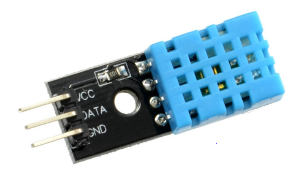
The DHT11 is a low cost temperature and humidity sensor that operates using the 1-wire protocol, costs about $2.
DHT11 Tempereature and Humidity Sensor
This sensor has three pins, the first pin is the power pin VCC, the middle pin is the signal out or DATA pin and the last pin is GND.
Although the DHT11 temperature and humidity sensor isn’t the fastest temperature and humidity sensor around, it has fair level of accuracy, +-5% for humidity readings and +-2% for temperature readings. With the DHT we will be able to measure temperature and humidity of the environment with a very fair degree of accuracy.
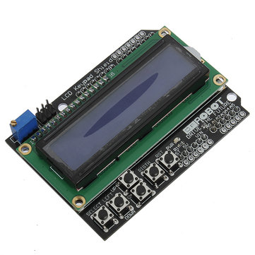
The LCD Keypad shield makes connecting the 16×2 LCD module to any system quite easy as it simply just plugs on the Arduino mega which is being used for this project.
LCD keypad shield
An ordinary 16×2 LCD module (not shield) can also be used. Just ensure the pins are connected as described in the code and schematic below.
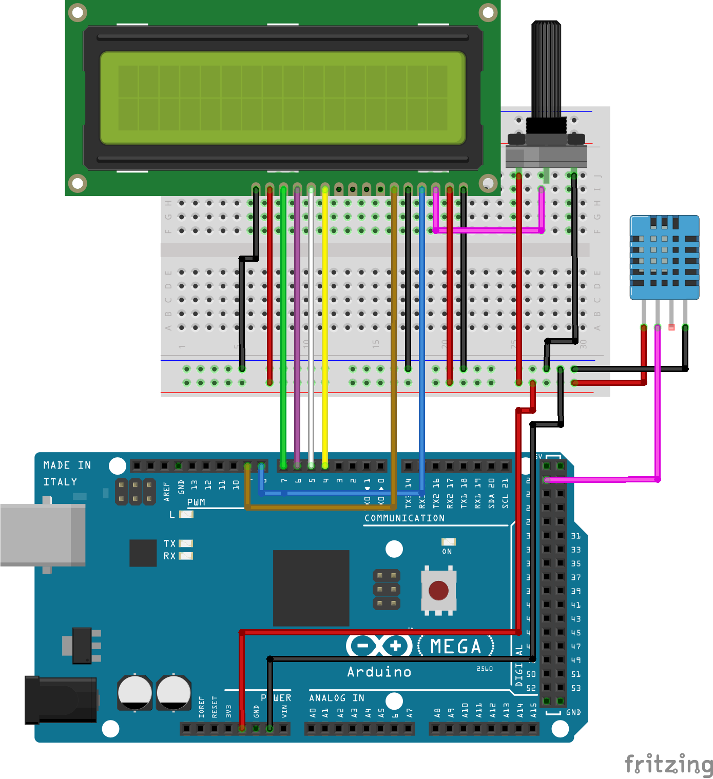
Schematic
Connect the LCD and the DHT11 sensor as shown in the image below.
Schematics
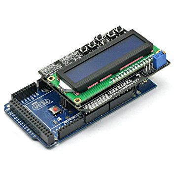
Putting the component together is very easy if using the LCD keypad shield. All you just need to do is plug the LCD in as shown below and connect the DHT as described in the schematics above.
LCD Shield Mounted on the Arduino Mega
For proper understanding of the connections, here is a breakdown of all the components connected.
Note that the RW pin is connected to GND because we will be writing only to the LCD and not to read from it, for this to be possible the RW pin has to be pulled LOW
DHT11 Connection
Pin connection of the dht11 to the arduino is as illustrated below. All DHT11 sensors have three main functional pins. The DHT types with four pins always have a void pin which is never connected to anything.
DHT11 - Arduino
VCC - 5V
DATA - D22
GND - GND
with the schematics handled, lets move to the code.
Code
Before we start, we have to download DHT library and set its type. The required library is available on github. Download it and extract it into Arduino libraries folder, then open Arduino IDE. Its probably important to note at this point that the library will not be visible to an Arduino IDE instance that was already running before installation, you have to restart the Arduino IDE after installing the library.
With our library installed, we can move to the code analysis:
The first thing to be done is to include all the dependencies the code needs to run fine, libraries in this case.
//written by Nick Koumaris
//info@educ8s.tv
//educ8s.tv

#include "DHT.h"
#include <LiquidCrystal.h>
Next we define the pin the DHT11 DATA pin is connected to and also include the type of the DHT sensor we are using which is DHT11.
#define DHTPIN 22     // what pin we're connected to

#define DHTTYPE DHT11
On line 4 we create a DHT object and then pass in the pin number (DHTPIN) and the sensor type (DHTTYPE).
DHT dht(DHTPIN, DHTTYPE);
With the next line, we create an LCD object, passing in the Arduino pin numbers to which our LCD pins are connected as follows in the format lcd (RS, E, D4, D5, D6, D7).
LiquidCrystal lcd(8,9,4,5,6,7);
with this done, we are ready to move into the setup function.
In the setup function, we call the LCD begin method, passing in the LCD size which is a 16×2. Next, we print a message to indicate the device has commenced reading data from the sensor on the first line of the LCD then call the DHT begin method.
Moving on to the loop() function, we create two variables of type float which will hold the temperature and humidity value, give it a delay of two seconds after reading values into them and then clear the LCD.
Next we create two character arrays both of size six and then we use the dtostrf function to convert our temperature and humidity value from type float to string and then we print it on the LCD. Note that the explicit typecasting used in the lcd.print() function ((char)223) is used to print the degree symbol on the display.
Save your code, connect your Mega to your computer and make sure under your tools menu, the board picked is “Arduino/Genuino Mega or Mega 2560” and also ensure the right COM port is selected. Click upload when done and you should have something like the Image below.
Demo
That’s it guys, if you have any issue leave it in the comment section.
Visit here to download the code for this tutorial.
You can also watch the video tutorial on this topic on youtube.
In this episode Shahriar repairs an Agilent PSA Series Spectrum Analyzer. The instrument generates many errors during self-alignment and produces no measurements below 3.2GHz. The block diagram of the unit is thoroughly presented and various possible failure points are considered. Based on the observation of the noise floor, the most likely cause is the second LO module. The measurement of the LO power indicates that the second LO power is fall below nominal.
Teardown, Repair & Analysis of an Agilent E4443A 3Hz – 6.7GHz PSA Series Spectrum Analyzer – [Link]
In this blog post you’re going to learn how to decode (parse a JSON string) and encode (generate a JSON string) with the ArduinoJson library using the Arduino with the Ethernet shield. This guide also works with the ESP8266 and ESP32 Wi-Fi modules with small changes.
Decoding and Encoding JSON with Arduino or ESP8266 – [Link]
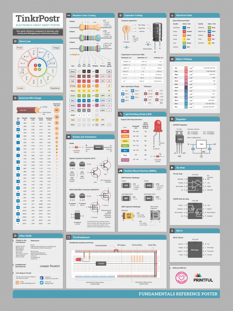
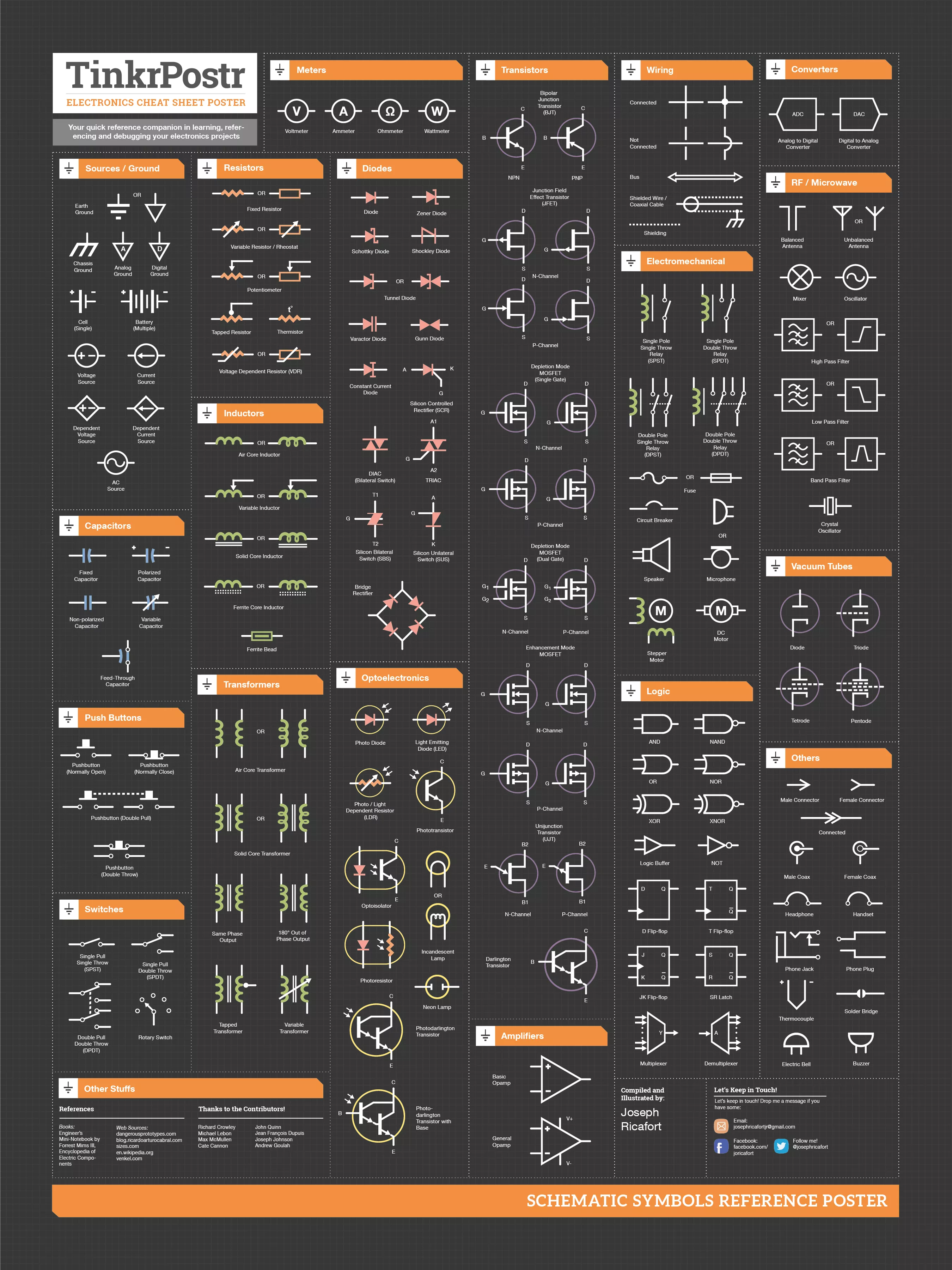
A quick reference in learning and debugging your electronics projects. Click to “download” the full resolution image + a bonus poster. or download ZIP file.
“Amirhossein Amini” has re-designed the above poster in Corel Draw and the source file can be downloaded here or PDF download.


