Another energy meter from Texas Instruments using MSP430AFE2xx. (PDF)
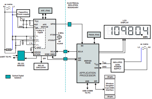
This application report describes the implementation of a single-phase electronic electricity meter using the Texas Instruments MSP430AFE2xx metering processors. It includes the necessary information with regard to metrology software and hardware procedures for this single chip implementation.
App note: Implementation of a single-phase electronic watt-hour meter using the MSP430AFE2xx – [Link]
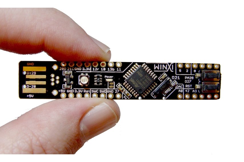
WINXI – arduino ZERO Pro M0 compatible stick, RGB led, Micro SD, AtSamD21E18. Arduino zero pro compatible board with USB programming suitable for experienced users.
The LT8650S is a dual step-down regulator that delivers up to 4A of continuous current from both channels and supports loads up to 6A from each channel. The LT8650S features the second generation Silent Switcher architecture to minimize EMI emissions while delivering high efficiency at high switching frequencies. This includes integration of bypass capacitors to optimize high frequency current loops and make it easy to achieve advertised EMI performance by eliminating layout sensitivity. Spread spectrum operation can further reduce EMI emissions. The fast, clean, low-overshoot switching edges enable high efficiency operation even at high switching frequencies, leading to a small overall solution size. Burst Mode operation features a 6.2μA quiescent current resulting in high efficiency at low output currents.
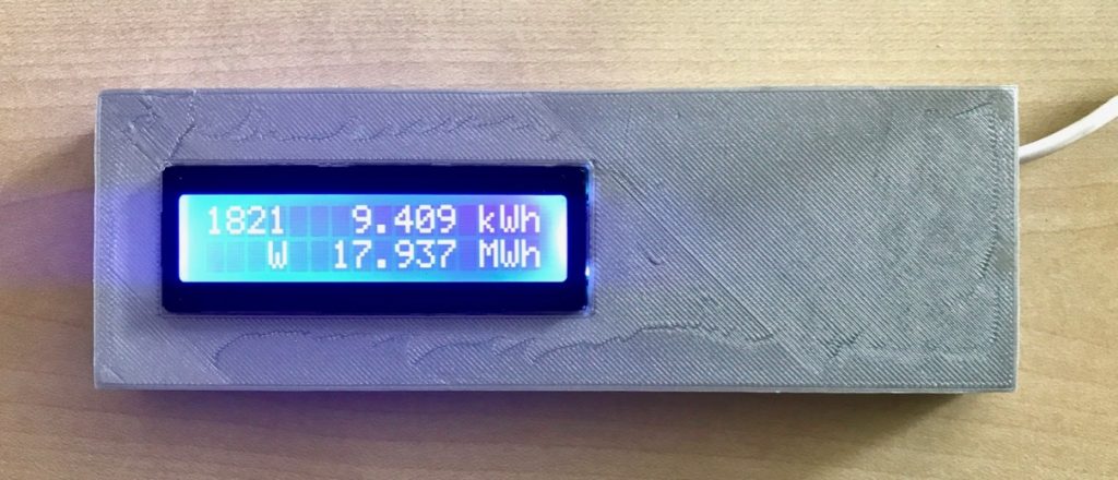
Jean-Claude wanted to read SMA solar inverter data over Bluetooth and so he build this project.
This is the first post of a 3-part series about reading out an SMA solar inverter over Bluetooth and displaying some readings every few seconds. Long-time readers may remember the Solar at last weblog post from several years ago and the SMA Relay, based on a JeeNode v6. The Bluetooth readout code was derived from Stuart Pittaway’s Nanode SMA PV Monitor code.
Make a sustainable Raspberry Pi backup server and save your files from occasional loss.
Raspberry Pi backup is what you really need if you work on Raspbian. Believe me, you do! If you backup your Raspberry Pi SD card in due course, someday it may save your files and your project. Alike any other hardware, the RPi devices may sometimes simply stop working.
It can occur due to a number of reasons: overheating, errors, energy supply issues, cable connection failure… All these problems will make you unplug and plug-in again the device to restart it. And such actions taken repeatedly will certainly lead to spoiling your SD card you are saving your work files to.
On the other hand, you can damage or delete your files occasionally with your own hands! There a lot of examples when we do something wrong because of the overall tiredness, inattentiveness or just being in a hurry.
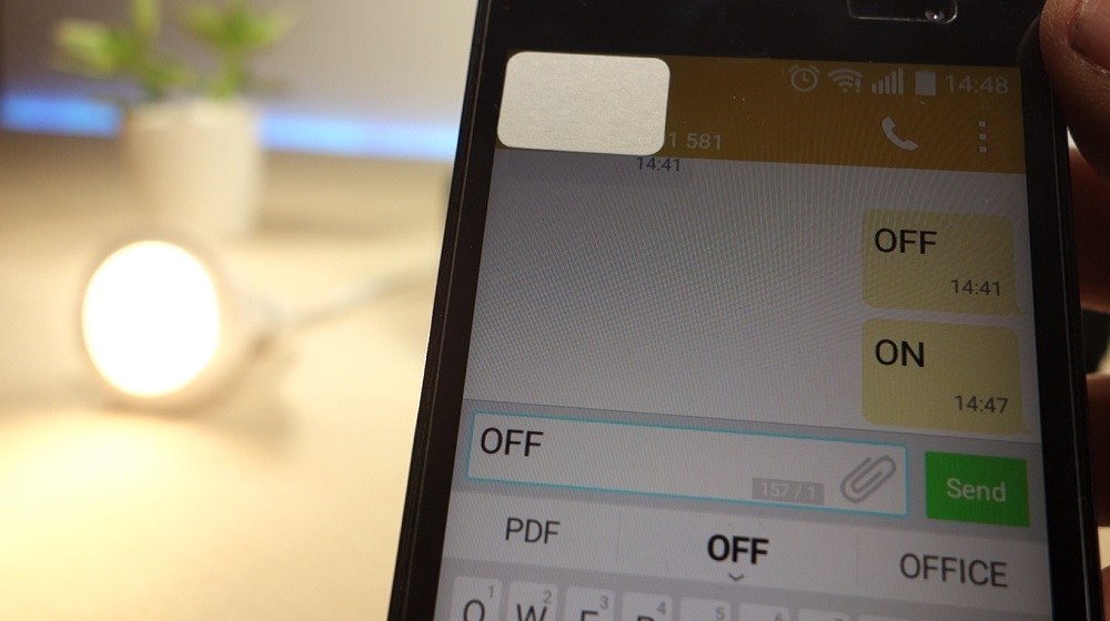
In this tutorial we’re going to show you how you can turn a 12V lamp on and off by sending SMS to your Arduino with the text “ON” and “OFF”, respectively. You can also request the current lamp state by sending an SMS with the text “STATE”, the Arduino should reply back with the text “Lamp is on” or “Lamp is off”
Hariharan Mathavan at allaboutcircuits.com designed a project on using Bluetooth to communicate with an Arduino. Bluetooth is one of the most popular wireless communication technologies because of its low power consumption, low cost and a light stack but provides a good range. In this project, data from a DHT-11 sensor is collected by an Arduino and then transmitted to a smartphone via Bluetooth.
Required Parts
An Arduino. Any model can be used, but all code and schematics in this article will be for the Uno.
An Android Smartphone that has Bluetooth.
HC-05 Bluetooth Module
Android Studio (To develop the required Android app)
USB cable for programming and powering the Arduino
DHT-11 temperature and humidity sensor
Connecting The Bluetooth Module
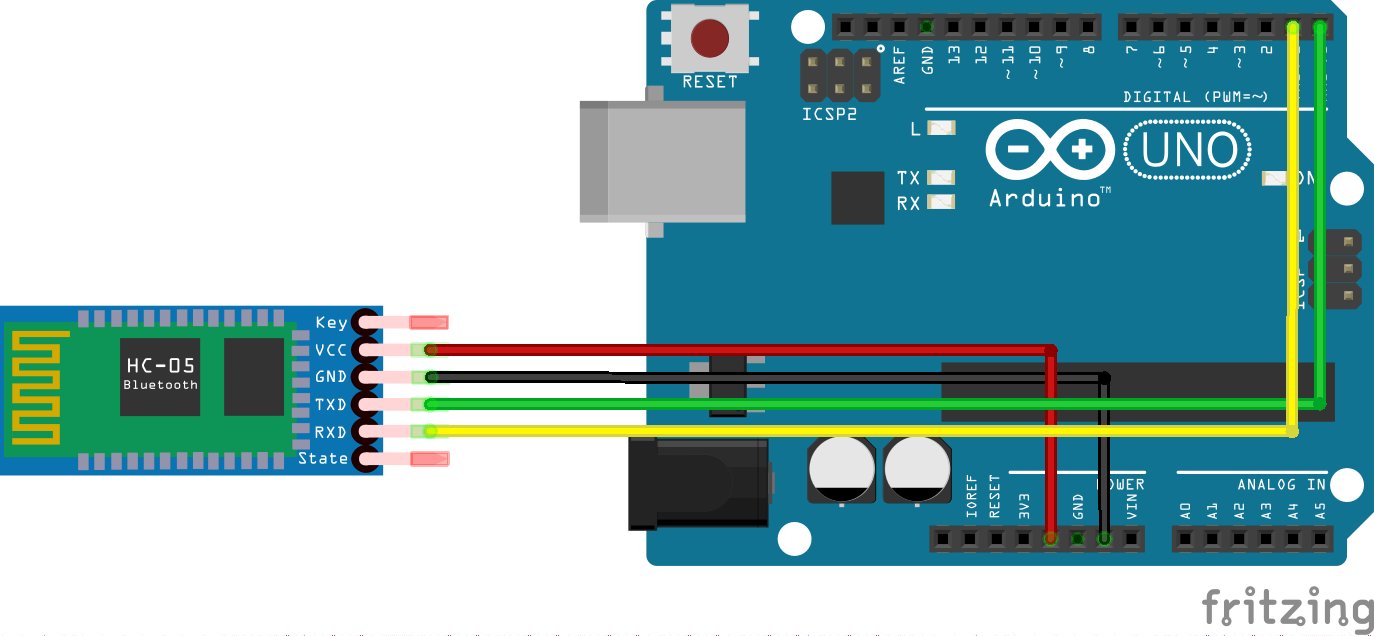
To use the HC-05 Bluetooth module, simply connect the VCC to the 5V output on the Arduino, GND to Ground, RX to TX pin of the Arduino, and TX to RX pin of the Arduino. If the module is being used for the first time, you’ll want to change the name, passcode etc. To do this the module should be set to command mode. Connect the Key pin to any pin on the Arduino and set it to high to allow the module to be programmed.
Circuit to connect HC-05 with Arduino
To program the module, a set of commands known as AT commands are used. Here are some of them:
AT
Check connection status.
AT+NAME =”ModuleName”
Set a name for the device
AT+ADDR
Check MAC Address
AT+UART
Check Baudrate
AT+UART=”9600″
Sets Baudrate to 9600
AT+PSWD
Check Default Passcode
AT+PSWD=”1234″
Sets Passcode to 1234
The Arduino code to send data using Bluetooth module:
//If youre not using a BTBee connect set the pin connected to the KEY pin high
#include <SoftwareSerial.h>
SoftwareSerial BTSerial(4,5);
void setup() {
 String setName = String("AT+NAME=MyBTBee\r\n"); //Setting name as 'MyBTBee'
 Serial.begin(9600);
 BTSerial.begin(38400);
 BTSerial.print("AT\r\n"); //Check Status
 delay(500);
 while (BTSerial.available()) {
 Serial.write(BTSerial.read());
 }
 BTSerial.print(setName); //Send Command to change the name
 delay(500);
 while (BTSerial.available()) {
 Serial.write(BTSerial.read());
 }}
void loop() {}
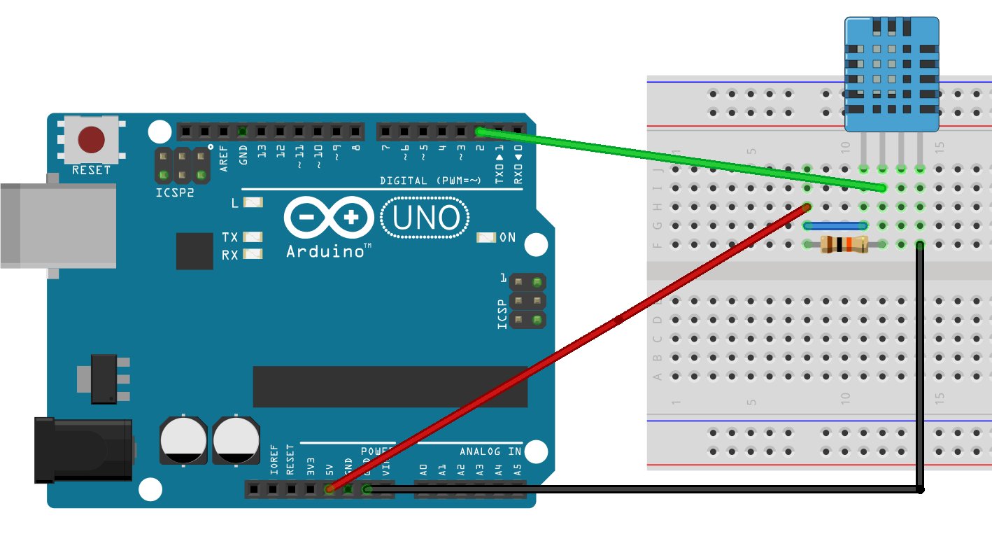
Connecting The DHT-11 Sensor
To use the DHT-11, the DHT library by Adafruit is used. Go here to download the library. When the letter “t” is received, the temperature, humidity, and heat index will be transmitted back via Bluetooth.
circuit to connect DHT-11 with Arduino
The code used to read data from the DHT sensor, process it and send it via Bluetooth:
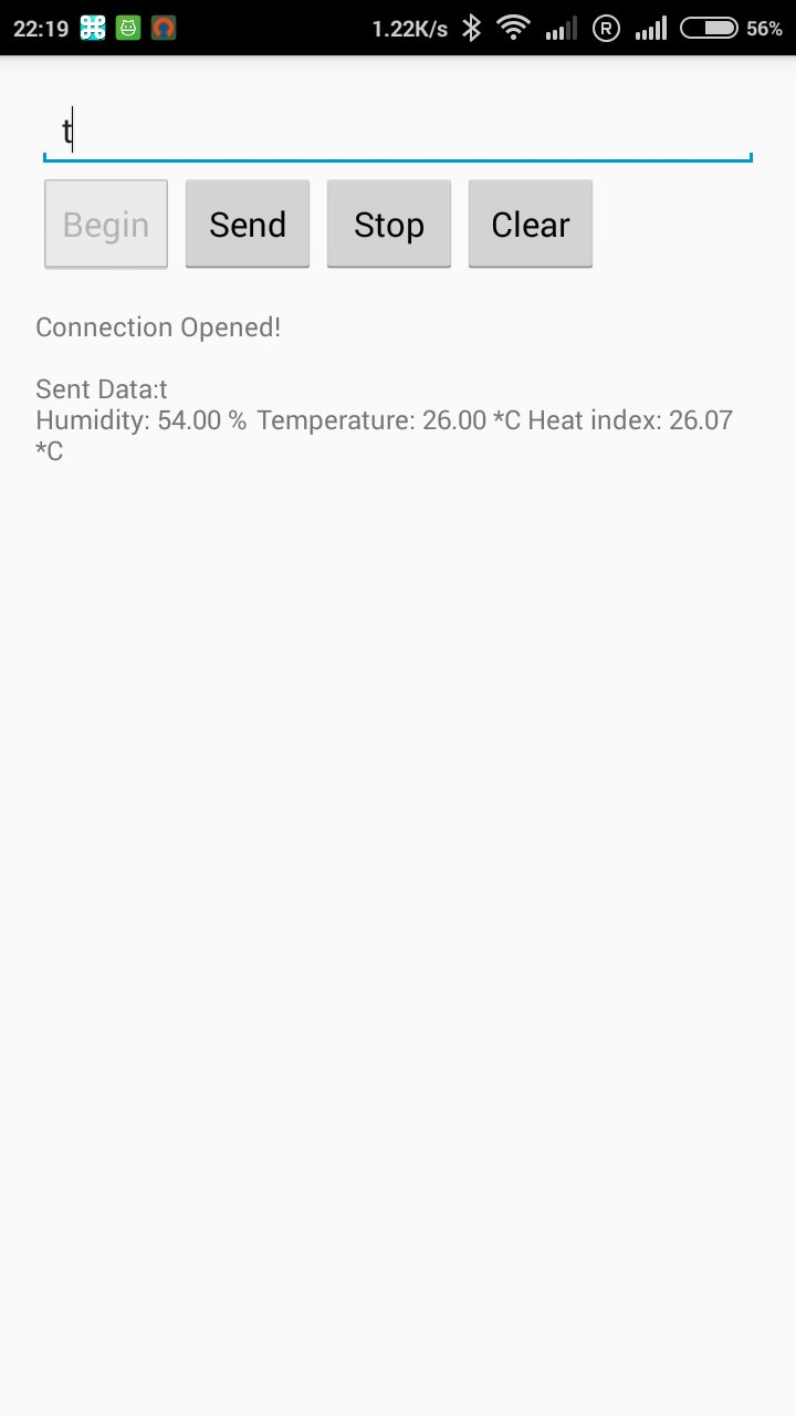
Power up the Arduino and turn on the Bluetooth from your mobile. Pair with the HC-05 module by providing the correct passcode – 0000 is the default one. Now, when “t” is sent to the Arduino, it replies with the Temperature, Humidity, and Heat Index.
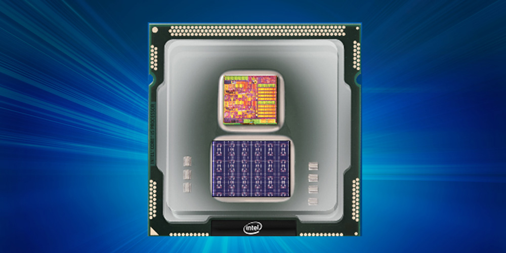
Intel has developed a first-of-its-kind self-learning neuromorphic chip – codenamed Loihi. It mimics the animal brain functions by learning to operate based on various modes of feedback from the environment. Unlike convolutional neural network (CNN) and other deep learning processors, Intel’s Loihi uses an asynchronous spiking model to mimic neuron and synapse behavior in a much closer analog to animal brain behavior.
Loihi – Intel’s self-learning chip
Machine learning models based on CNN use large training sets to set up recognition of objects and events. This extremely energy-efficient chip, which uses the data to learn and make inferences, gets smarter over time and does not need to be trained in the traditional way. The Loihi chip includes digital circuits that mimic the brain’s basic mechanics, making machine learning faster and more efficient while requiring much lower computing power.
The chip offers highly flexible on-chip learning and combines training and inference on a single chip. This allows machines to be autonomous and to adapt in real time instead of waiting for the next update from the cloud. Compared to convolutional neural networks and deep learning neural networks, the Loihi test chip uses many fewer resources on the same task. Researchers have demonstrated learning at a rate that is a 1 million times improvement compared with other typical neural network devices.
The self-learning capabilities prototyped by this test chip have huge potential to improve automotive and industrial applications as well as personal robotics – any application that would benefit from the autonomous operation and continuous learning in an unstructured environment. For example, recognizing the movement of a car or bike for an autonomous vehicle. More importantly, it is up to 1,000 times more energy-efficient than general purpose computing.
Features
Fully asynchronous neuromorphic many core mesh.
Each neuron capable of communicating with thousands of other neurons.
Each neuromorphic core includes a learning engine that can be programmed to adapt network parameters during operation.
Fabrication on Intel’s 14 nm process technology.
A total of 130,000 neurons and 130 million synapses.
Development and testing of several algorithms with high algorithmic efficiency for problems including path planning, constraint satisfaction, sparse coding, dictionary learning, and dynamic pattern learning and adaptation.
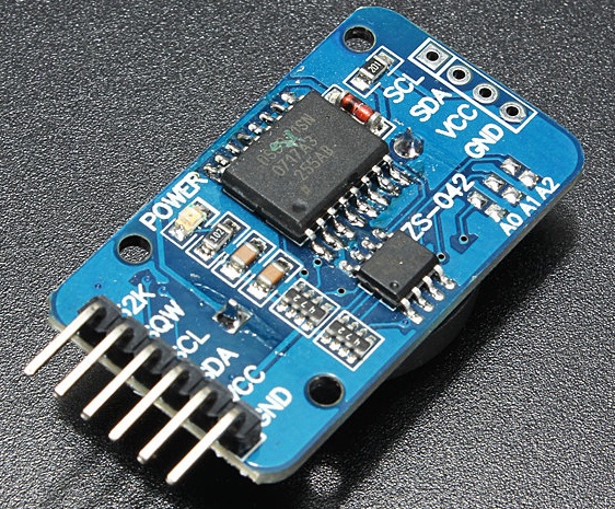
The DS3231 is a very low power RTC chip, it has the ability to keep time with incredible accuracy such that even after power has been disconnected from your product, it can run for years on a connected coin cell battery. This module has the ability to communicate via I2C or SPI but for this tutorial we will be using the I2C mode for communications between our arduino and the DS3231. The module also comes with a quite accurate temperature sensor which we will be using to get temperature readings. The collected temperature and clock data is then displayed on the 16×2 LCD via the Arduino.
Real Time Clock and Temperature Monitor using DS3231 Module – [Link]
Hi guys, welcome to this tutorial. One of the most important things everyone wants to keep track of daily is, time and with easy to use platforms like the arduino it is very easy to create your own timepiece and in the case of this tutorial add a temperature monitor to it.
For this tutorial, we will be creating a real-time clock and temperature monitor using the simple and easy to use DS3231 module.
DS3231 Real Time Clock Module
The DS3231 is a very low power RTC chip, it has the ability to keep time with incredible accuracy such that even after power has been disconnected from your product, it can run for years on a connected coin cell battery. This module has the ability to communicate via I2C or SPI but for this tutorial we will be using the I2C mode for communications between our arduino and the DS3231. The module also comes with a quite accurate temperature sensor which we will be using to get temperature readings. The collected temperature and clock data is then displayed on the 16×2 LCD via the Arduino.
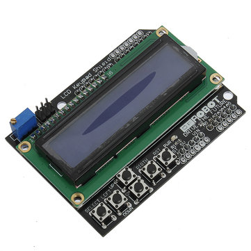
LCD Keypad Shield
Required Components
The following components will be needed for this tutorial. They can be purchased via the links attached.
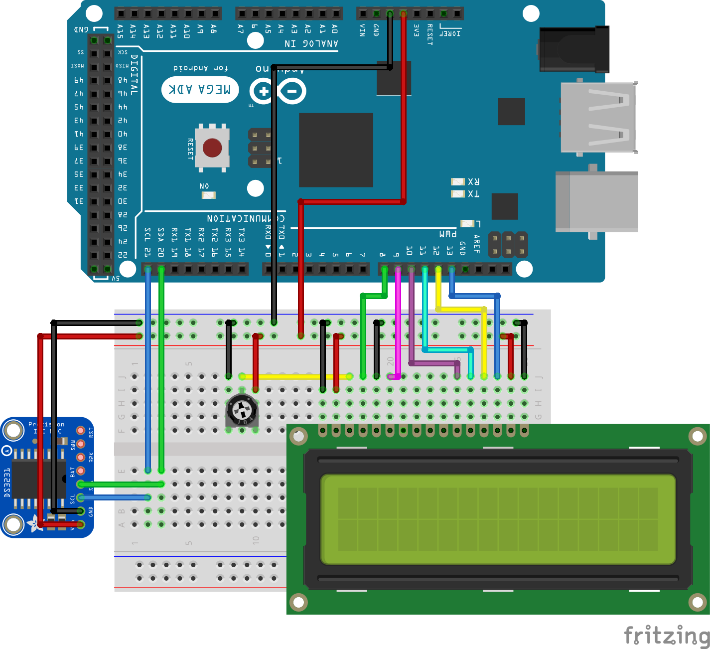
Connect all components as shown in the Fritzing schematics below, kindly note the LCD connection will not be needed if using the shield.
Since the DS3231 is going to communicate via I2C then its I2C pins will be connected to the arduino’s I2C (SDA and SCL) pins which on the mega are located on pin A0 and A1 or pin 20 (SDA) and 21 (SCL) of the arduino mega.
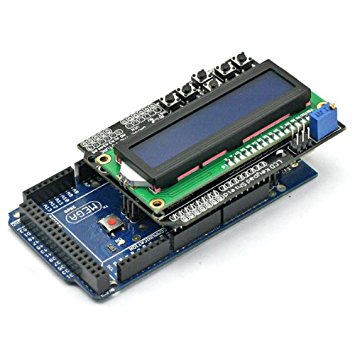
Next connection is between the LCD and the Arduino. If you are using the screen and keypad shield whose link is attached above, all you will just need to do is plug it in to your arduino as shown below.
LCD Keypad shield Mounted on the Arduino
If not then you can connect it as described in the schematics and illustrated below.
With the connections done, lets jump into writing the code.
The first thing we need to do is to download the arduino library for the ds3231 RTC. The library can be found here and is also attached at the end of this project. Rename the library to “RTC” and install it, by copying and pasting into the Arduino libraries folder.
Launch the Arduino IDE and copy in the Attached code.
To do a break down of the code, the first thing we do in the code is to include the libraries that carry some of the dependencies needed for our code to run. The Libraries include wire.h to enable I2C communication, Ds3231.h and rtc_ds3231.h to enable the RTC to work and the Liquidcrystal.h which makes it easy for us to work with the LCD.
//Written by Nick Koumaris
//info@educ8s.tv
//educ8s.tv

#include <Wire.h>
#include "ds3231.h"
#include "rtc_ds3231.h"
#include <LiquidCrystal.h>
The next thing is to declare the LCD pins and move into the setup function
The code is a modified version of the example found in the arduino library. The first thing we will be doing with the code is setting the time of the ds3231. The time is set using this line under the setup section.
2014 is the year,
10 is the month
04 is the day of the month
6 is the day of the week
11 is hour of the day (its 11 am here)
29 is the minute
30 is the seconds
you can change this to match your current date when setting the time.
The device does not come with time preset but after setting it once, the action will no longer be needed.
The next thing after this is to move into the loop function. The loop function displays the time and temperature on the LCD after querying the DS3231 module.
void loop()
{
    char in;
    char tempF[6];
    float temperature;
    char buff[BUFF_MAX];
    unsigned long now = millis();
    struct ts t;

    // show time once in a while
    if ((now - prev > interval) && (Serial.available() <= 0)) {
        DS3231_get(&t); //Get time
        parse_cmd("C",1);
        temperature = DS3231_get_treg(); //Get temperature
        dtostrf(temperature, 5, 1, tempF);

        lcd.clear();
        lcd.setCursor(1,0);

        lcd.print(t.mday);

        printMonth(t.mon);

        lcd.print(t.year);

        lcd.setCursor(0,1); //Go to second line of the LCD Screen
        lcd.print(t.hour);
        lcd.print(":");
        if(t.min<10)
        {
          lcd.print("0");
        }
        lcd.print(t.min);
        lcd.print(":");
        if(t.sec<10)
        {
          lcd.print("0");
        }
        lcd.print(t.sec);

        lcd.print(' ');
        lcd.print(tempF);
        lcd.print((char)223);
        lcd.print("C ");
        prev = now;
    }


    if (Serial.available() > 0) {
        in = Serial.read();

        if ((in == 10 || in == 13) && (recv_size > 0)) {
            parse_cmd(recv, recv_size);
            recv_size = 0;
            recv[0] = 0;
        } else if (in < 48 || in > 122) {;       // ignore ~[0-9A-Za-z]
        } else if (recv_size > BUFF_MAX - 2) {   // drop lines that are too long
            // drop
            recv_size = 0;
            recv[0] = 0;
        } else if (recv_size < BUFF_MAX - 2) {
            recv[recv_size] = in;
            recv[recv_size + 1] = 0;
            recv_size += 1;
        }

    }
}
The next block of code is the parse_cmd function that was used to set the time.
void parse_cmd(char *cmd, int cmdsize)
{
    uint8_t i;
    uint8_t reg_val;
    char buff[BUFF_MAX];
    struct ts t;

    //snprintf(buff, BUFF_MAX, "cmd was '%s' %d\n", cmd, cmdsize);
    //Serial.print(buff);

    // TssmmhhWDDMMYYYY aka set time
    if (cmd[0] == 84 && cmdsize == 16) {
        //T355720619112011
        t.sec = inp2toi(cmd, 1);
        t.min = inp2toi(cmd, 3);
        t.hour = inp2toi(cmd, 5);
        t.wday = inp2toi(cmd, 7);
        t.mday = inp2toi(cmd, 8);
        t.mon = inp2toi(cmd, 10);
        t.year = inp2toi(cmd, 12) * 100 + inp2toi(cmd, 14);
        DS3231_set(t);
        Serial.println("OK");
    } else if (cmd[0] == 49 && cmdsize == 1) {  // "1" get alarm 1
        DS3231_get_a1(&buff[0], 59);
        Serial.println(buff);
    } else if (cmd[0] == 50 && cmdsize == 1) {  // "2" get alarm 1
        DS3231_get_a2(&buff[0], 59);
        Serial.println(buff);
    } else if (cmd[0] == 51 && cmdsize == 1) {  // "3" get aging register
        Serial.print("aging reg is ");
        Serial.println(DS3231_get_aging(), DEC);
    } else if (cmd[0] == 65 && cmdsize == 9) {  // "A" set alarm 1
        DS3231_set_creg(DS3231_INTCN | DS3231_A1IE);
        //ASSMMHHDD
        for (i = 0; i < 4; i++) {
            time[i] = (cmd[2 * i + 1] - 48) * 10 + cmd[2 * i + 2] - 48; // ss, mm, hh, dd
        }
        boolean flags[5] = { 0, 0, 0, 0, 0 };
        DS3231_set_a1(time[0], time[1], time[2], time[3], flags);
        DS3231_get_a1(&buff[0], 59);
        Serial.println(buff);
    } else if (cmd[0] == 66 && cmdsize == 7) {  // "B" Set Alarm 2
        DS3231_set_creg(DS3231_INTCN | DS3231_A2IE);
        //BMMHHDD
        for (i = 0; i < 4; i++) {
            time[i] = (cmd[2 * i + 1] - 48) * 10 + cmd[2 * i + 2] - 48; // mm, hh, dd
        }
        boolean flags[5] = { 0, 0, 0, 0 };
        DS3231_set_a2(time[0], time[1], time[2], flags);
        DS3231_get_a2(&buff[0], 59);
        Serial.println(buff);
    } else if (cmd[0] == 67 && cmdsize == 1) {  // "C" - get temperature register
        Serial.print("temperature reg is ");
        Serial.println(DS3231_get_treg(), DEC);
    } else if (cmd[0] == 68 && cmdsize == 1) {  // "D" - reset status register alarm flags
        reg_val = DS3231_get_sreg();
        reg_val &= B11111100;
        DS3231_set_sreg(reg_val);
    } else if (cmd[0] == 70 && cmdsize == 1) {  // "F" - custom fct
        reg_val = DS3231_get_addr(0x5);
        Serial.print("orig ");
        Serial.print(reg_val,DEC);
        Serial.print("month is ");
        Serial.println(bcdtodec(reg_val & 0x1F),DEC);
    } else if (cmd[0] == 71 && cmdsize == 1) {  // "G" - set aging status register
        DS3231_set_aging(0);
    } else if (cmd[0] == 83 && cmdsize == 1) {  // "S" - get status register
        Serial.print("status reg is ");
        Serial.println(DS3231_get_sreg(), DEC);
    } else {
        Serial.print("unknown command prefix ");
        Serial.println(cmd[0]);
        Serial.println(cmd[0], DEC);
    }
}
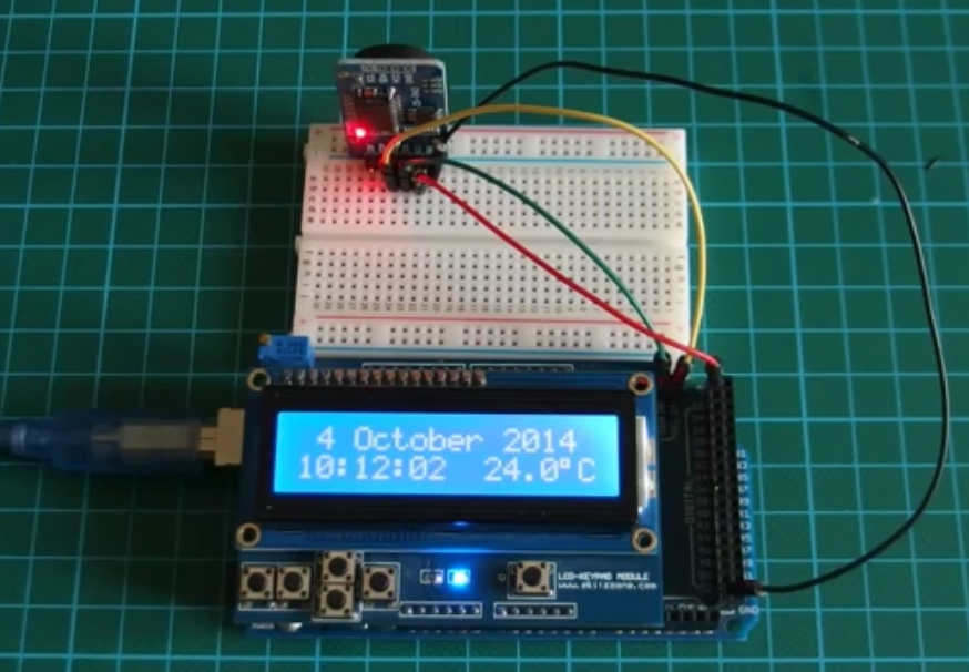
After uploading the code for the first time, the time setting part in the setup() is then commented out and the code can be uploaded again.
You should then see something like the image below.
Time and Temperature displayed on LCD
A youtube video on how the project works can be found here. The video tutorial is created by educ8s.tv channel
The source code, library and other files can be downloaded from here RTCCODE
That’s it guys!, let me know if you have any questions, I will be glad to help.