

Teardown & Experiments with an Anritsu MS9710B 0.6-1.75um Optical Spectrum Analyzer – [Link]
Researchers Developed Hybrid 3D Printing Method To Make Flexible Wearable Devices

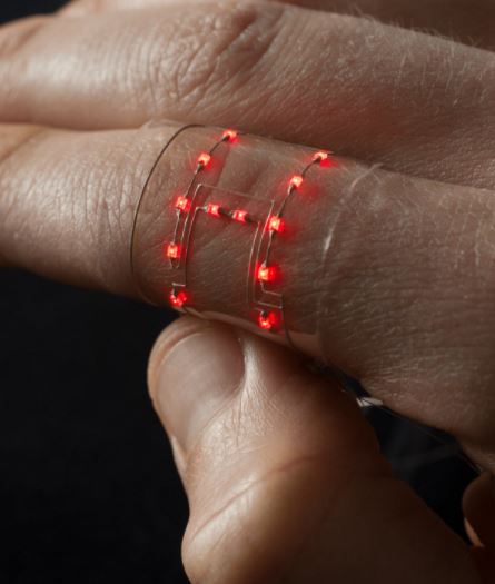
Wearable electronic devices that intend to track and measure the body’s movements must be soft enough to flex and stretch to accommodate every body-movement. But, integrating rigid electronics on skin-like flexible materials has proven to be challenging. Clearly, Such components cannot stretch like soft materials can, and this mismatch frequently causes wearable devices to fail. Recently scientists solved this problem by developing a new method called hybrid 3D printing.
A collaboration between the Wyss Institute, Harvard’s John A. Paulson School of Engineering and Applied Sciences, and the Air Force Research Laboratory, has resulted in developing hybrid 3D printing method. It combines soft, electrically conductive inks, and matrix materials with rigid electronics into a uniformly stretchable device. Alex Valentine, a Staff Engineer at the Wyss Institute says,
With this technique, we can print the electronic sensor directly onto the material, digitally pick-and-place electronic components, and print the conductive interconnects that complete the electronic circuitry required to ‘read’ the sensor’s data signal in one fell swoop.
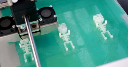
To make the circuits and the flexible layers, the researchers use thermoplastic polyurethane (TPU), both pure and with silver flakes. The method is quite easy to understand. As both the substrate and the electrodes contain TPU, they firmly adhere to one another while they are co-printed layer-by-layer. After the solvent evaporates completely, both of the inks harden, forming an integrated system that is both flexible and stretchable.
As the ink and substrate are 3D-printed, the scientists have complete control over where and how the conductive features are patterned. Thus they can design circuits to create soft electronic devices of nearly every size and shape. The hybrid 3D printing method enables development of flexible, durable wearable devices that move with the body.
Conductive materials exhibit changes in their electrical conductivity when stretched. Soft sensors, that detect movements, are made of those materials and are coupled with a programmable microcontroller to process those data. The microcontroller also transmits the data to communicate in a human-understandable way. As a proof-of-concept, the team created two devices – a wearable device that indicates how much the wearer’s arm is bending and a pressure sensor in the shape of a person’s left foot.
Watch the video to know about them,
Dual Channel Inductive Loop Vehicle Detector

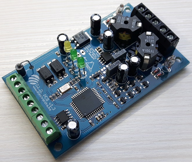
Muris @ elektronika.ba tipped us with his latest project. It’s a revision of their single channel loop detector published some time ago and it come with some nice features.
There are two PCB versions available, one is a standalone version (PCB v1.2) with DIPs and relays on board and another one is a digital version (PCB v1.3) without DIPs and relays where it requires PC or another microcontroller system to be connected in order to configure the operating parameters. Here we will be focusing on the standalone version.
Dual Channel Inductive Loop Vehicle Detector – [Link]
Overclocked Intel CPU draws 1kW

by Thomas Scherer @ elektormagazine.com
The impressively powerful i9-7980XE CPU from Intel boasts not just 18 cores and 36 threads but also an unlocked clock multiplier. The spec was clearly an open invitation to Roman Hartung who has something of a reputation when it comes to overclocking processors. In tests he was able to crank up the clock of this beast to 5.7 GHz at which point the CPU draws around 1kW of power.
Overclocked Intel CPU draws 1kW – [Link]
DSETA board with an AT89C51ED2

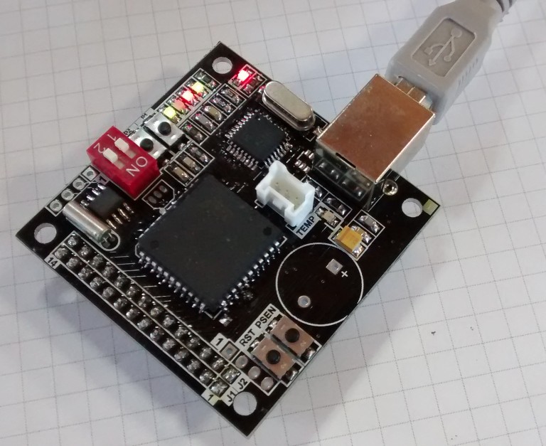
Jesus Echavarria tipped us with his latest DSETA board with an AT89C51ED2.
Some months ago I review the DSETA board due the obsolescence of the microcontroller. I use this board in some projects succesfully. But when I try to manufacture a batch of this boards, I found that the microcontroller (AT89C51RE2) was obsolete. So, the board needs an update to change the microcontroller and maintain most of the features that it has. Now that Microchip buys Atmel, obsolescence and samples will not be a problem.
To replace the RE2 microcontroller, I choose one very similar, the AT89C51ED2 microcontroller. Mainly because it shares most of features with the old one and footprint and pinout is almost the same, so replacement is relatively easy to do.
DSETA board with an AT89C51ED2 – [Link]
20 PIN PIC Development Board
Small size multipurpose 20 Pin PIC Micro-Controller development board, includes onboard 5V regulator, prototyping area and ICSP programing port. The board provided with few more components which includes 4 optocoupler, 2 LEDs connected to RA5, RC7 with series resistors, 2 tactile switches and 2 Trimmer Potentiometers. These components help to implement Microchip’s AN1660 single phase AC Motor driver. Just need 3 Phase Inverter IPM module to complete the Motor driver, Code and documents can be obtained from Microchip website. However these components can be used to implement other application or can be left unsoldered.
Features
- Supply 7-12V DC
- 20 PIN SO20 PIC16F1509 Micro-controller
- On Board 5V Regulator
- Connector for Microchip AN1660
- CN5 5V Isolated supply required if Microchip AN1660 Used
- On Board PIC programing ICSP port
- Two Connected LED on RC7, RA5 port Pin
20 PIN PIC Development Board – [Link]
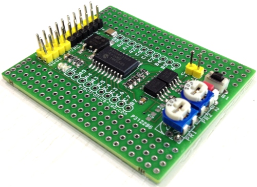
20 PIN PIC Development Board

Small size multipurpose 20 Pin PIC Micro-Controller development board, includes onboard 5V regulator, prototyping area and ICSP programing port. The board provided with few more components which includes 4 optocoupler, 2 LEDs connected to RA5, RC7 with series resistors, 2 tactile switches and 2 Trimmer Potentiometers. These components help to implement Microchip’s AN1660 single phase AC Motor driver. Just need 3 Phase Inverter IPM module to complete the Motor driver, Code and documents can be obtained from Microchip website. However these components can be used to implement other application or can be left unsoldered.
Features
- Supply 7-12V DC
- 20 PIN SO20 PIC16F1509 Micro-controller
- On Board 5V Regulator
- Connector for AN1660
- CN5 5V Isolated supply required if Microchip AN1660 Used
- On Board PIC programing ICSP port
- Two Connected LED on RC7, RA5 port Pin
Microcontroller Features
- Enhanced Mid-range Core with 49 Instruction, 16 Stack Levels
- Flash Program Memory with self read/write capability
- High Endurance Flash Memory (HEF)
- 128 B of Non-volatile Data Storage
- Internal 16MHz oscillator
- 4x Standalone PWM
- Complementary Waveform Generator (CWG)
- Numerically Controlled Oscillator (NCO)
- 4x Configurable Logic Cell (CLC)
- Integrated Temperature Indicator
- 12 Channel 10-bit ADC with Voltage Reference
- 5-bit Digital to Analog Converter (DAC)
- MI2C, SPI, EUSART w/auto baud
- 25mA Source/Sink current I/O
- 2x 8-bit Timers (TMR0/TMR2)
- 1x 16-bit Timer (TMR1)
- Extended Watchdog Timer (WDT)
- Enhanced Power-On/Off-Reset
- Low-Power Brown-Out Reset (LPBOR)
- Programmable Brown-Out Reset (BOR)
- In Circuit Serial Programming (ICSP)
- Integrated In-Circuit Debug / or Use an ICD Header
- Wide Operation Voltage Variant ‘F’ (1.8V – 5.5V)
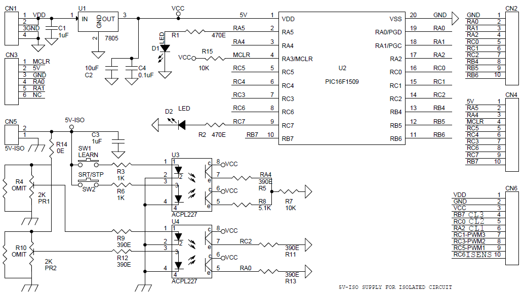
Schematic
Parts List

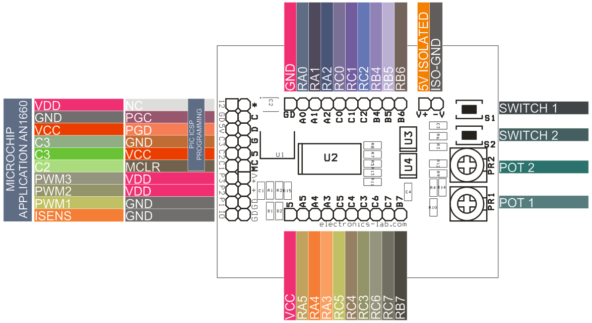
Connections
MaxProLogic: Ultra Low Cost FPGA Development Board

The MaxProLogic is the perfect FPGA project board for the student and hobbyist.
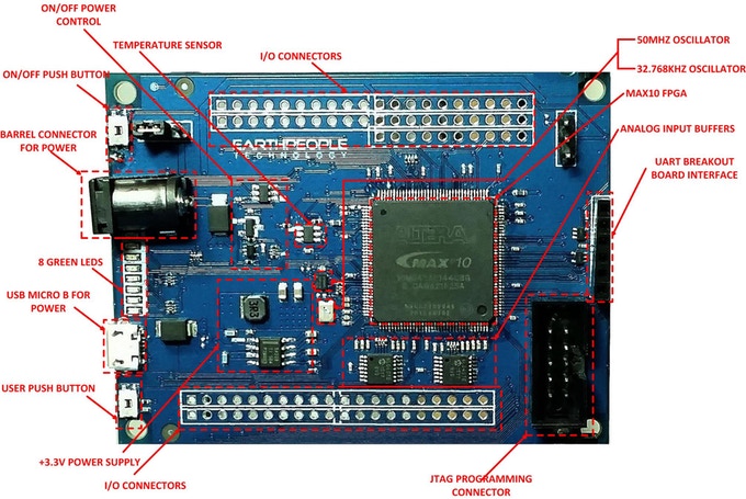
The MaxProLogic is an FPGA development board that is designed to be user friendly and a great introduction into digital design for anyone. The core of the MaxProLogic is the Altera MAX10 FPGA. This powerful chip has 4,000 Logic Elements and 200Kbits of Memory. The MAX10 is easily scalable from the entry level college student to the most advanced projects like an audio sound meter with FFT. Upon the many great features of the MaxProLogic is the MAX10 chip has a built in Flash for configuration and incorporates 8 channels of Analog to Digital Conversion. These two features alone create a far superior FPGA chip than any competitor on the market. It allows the user to create more diverse projects.
MaxProLogic: Ultra Low Cost FPGA Development Board – [Link]
LoFive – Tiny RISC-V Microcontroller Board

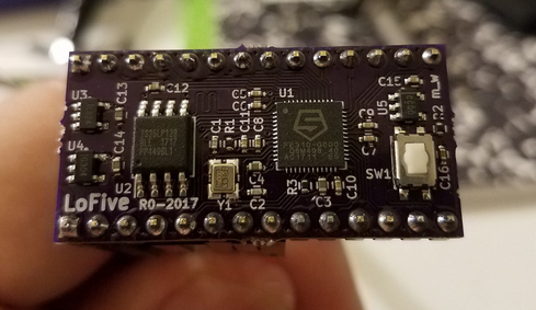
Small breadboard friendly development board using the SiFive FE310 RISC-V Microcontroller.
- MCU – SiFive Freedom E310 (FE310) 32-bit RV32IMAC processor @ up to 320+ MHz (1.61 DMIPS/MHz)
- Storage – 128-Mbit SPI flash (ISSI IS25LP128)
- Expansion – 2x 14-pin headers with JTAG, GPIO, PWM, SPI, UART, 5V, 3.3V and GND
- Misc – 1x reset button, 16 MHz crystal
- Power Supply – 5V via pin 1 on header; Operating Voltage: 3.3 V and 1.8 V
- Dimensions – 38 x 18 mm (estimated)
- License – CERN Open Hardware Licence v1.2
LoFive – Tiny RISC-V Microcontroller Board – [Link]
Alzheimer’s Wearable Assistant


A smartwatch with fall and location detection, reminders and more, designed to help you or your loved one with Alzheimer’s!
When I saw Infineon’s Sensor Hub Nano, it appeared to be a good candidate in such a project, because of its very small size and BLE capabilities. With the accurate pressure sensing, it could be used to detect if the patient has fallen and also tell where exactly the patient is in the house.
Alzheimer’s Wearable Assistant – [Link]