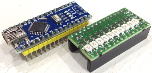
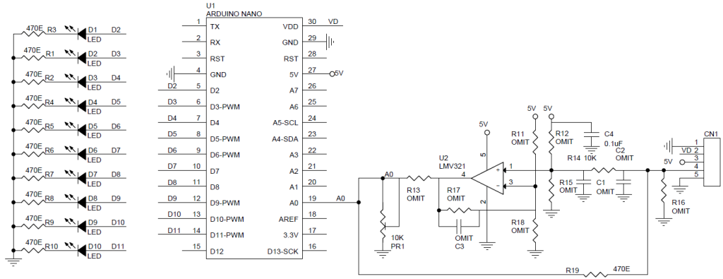
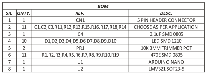
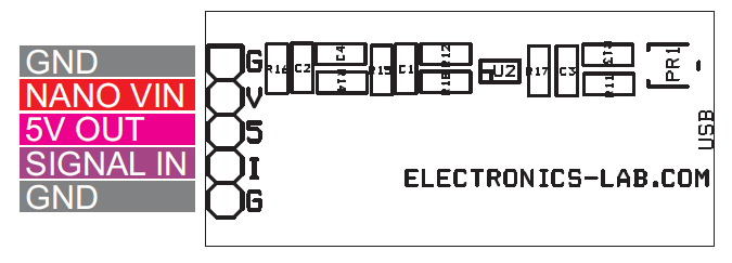
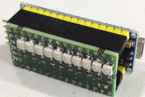
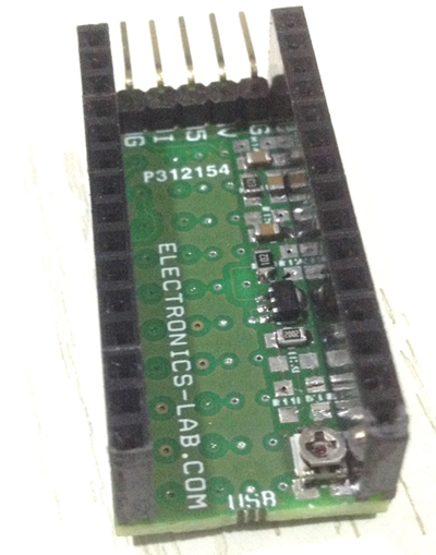
Arduino Nano Bar-Graph display with universal op-amp shield consists of 10 LEDs and single low voltage general purpose LMV321 op amp including few capacitors and resistors connected to op-amp pins. The op-amp proto area can be configured without any modifications to the board and all that is necessary is to select the correct resistors and capacitors. The other optional components can be left open or shorted depending on the configuration desired. All 10 LED comes with current limiting series resistors connected to digital pins D2 to D11 of Arduino Nano, Nano analog pin A0 used as input, the input can be used directly as voltage input to measure the voltage and display on Bar-graph.
0 To 5V Bar-graph volt meter with 0.5V step is simplest project possible with the shield, many other sensor based application possible using op-amp as signal conditioning amplifier.
Code for Simple Bar-Graph Voltmeter with 0-5V range is available here.
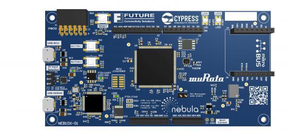
Together with partners Cypress Semiconductor and Murata, distributor Future Electronics has launched the Nebula IoT Development Kit, an IoT cloud ready board that allows developers to quickly prototype and deploy their IoT ecosystems. by Julien Happich :
Wireless connectivity is supported by the Murata 1DX module, which is powered by the Cypress CYW4343W Wi-Fi and BT/BLE combo SoC.
The SoC includes a 2.4 GHz WLAN IEEE 802.11 b/g/n baseband/radio and Bluetooth 4.2 support. In addition, it integrates a high-performance power amplifier (PA), a low-noise amplifier (LNA) for best-in-class receiver sensitivity, and an internal transmit/receive (iTR) RF switch, further reducing the overall system cost and 1DX module size
IoT cloud development kit is Wi-Fi and BT/BLE-ready – [Link]
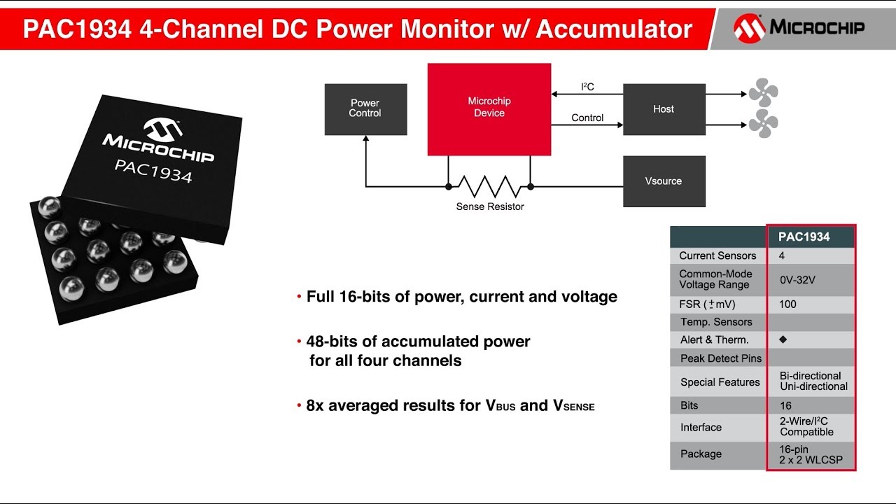
Microchip recently developed a precision power-and-energy-monitoring chip – PAC1934. The PAC1934 is a four channel power/energy monitor with current sensor amplifier and bus voltage monitors that feed high-resolution ADC. It works in conjunction with a Microchip software driver that is fully compatible with the Energy Estimation Engine (E3) built into the Windows 10 operating system. The whole setup provides 99 percent accuracy on all battery-powered Windows 10 devices.
PAC1934 – Software power monitoring IC
The PAC1934 enables energy monitoring with a wide range of integration periods from 1 ms to up to 36 hours. Combining Microchip’s PAC1934 chip and Microsoft’s E3 service can enhance the measurement of battery usage by different applications up to 29 percent. The sophisticated digital circuitry of the IC performs power calculations and energy accumulation precisely.
The PAC1934 is able to measure voltage accurately as low as 0V and as high as 32V. This ability lets the chip precisely measure power usage from the Central Processing Unit (CPU) as well as from software running on devices connected through a USB Type-C connector. The chip has features that could make it an essential part of future software upgrades. No input filters are required for this chip as it uses real-time calibration to suppress offset and gain errors.
The PAC1934 measures bus voltage, sense resistor voltage, and accumulated proportional power. Then stores the data in 16-bit registers for retrieval by the system master or embedded controller. The data transfer between the chip and the host system is performed over SMBus or I2C. The sampling rate and energy integration period can also be controlled similarly. Another important feature is its highly configurable controls, such as Active channel selection and one-shot measurements.
Most important features are:
100 mV full-scale voltage sense range, 16-bit resolution.
Bidirectional or unidirectional options.
Wide bus voltage measurement range 0V to 32V, 16-Bit Resolution.
1% power measurement accuracy.
48-bit power accumulator register for recording data.
24-bit accumulator count.
User programmable sampling rates of 8, 64, 256, 1024 samples per second.
36 hours of power data accumulation at 8 samples per second.
2.7V to 5.5V supply operation.
Separate I/O pin for digital I/O 1.62-5.5V.
I2C fast mode plus (1Mp/S) and SMBus 3.0.
For more information on this IC, visit Microchip’s website here.
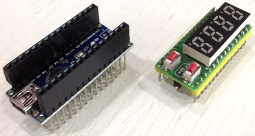
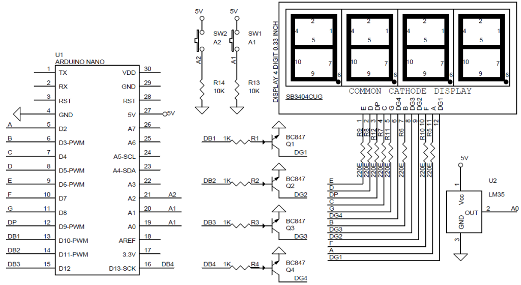
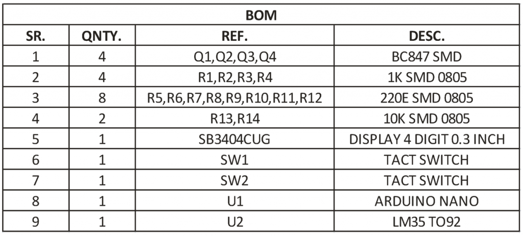
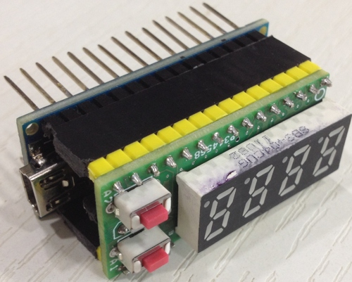
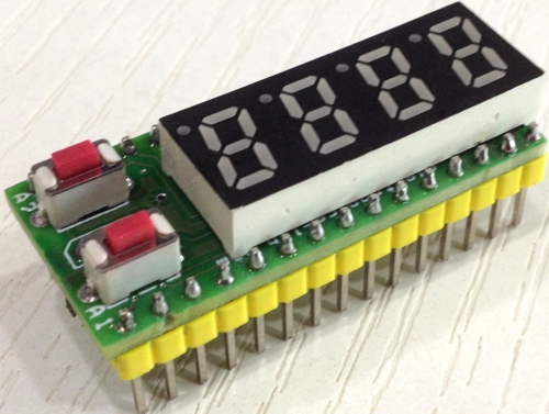
4 Digit Multiplexed display shield for Arduino Nano with on board 2 tactile switches and LM35 temperature sensor. This shield helps you to develop many projects that require 4 digit display. For example a thermometer can be made using on board LM35 sensor. 7 Seven segment multiplexed display is a tiny board and has been designed around Common cathode 4 digit Display. Display has 12 Pins. The board is provided with current limiting resistors on all LED segments and 4 NPN Transistors to drive 4 digits. This tiny board directly seats on Arduino Nano. Nano analog pin A0 connected to LM35 sensor, A1 and A2 connected to Switch 1 and switch 2 with pull down resistors. Digital pin D2-D8 connected to displays segment A-F, Digital pin D9 connected to DP of display, D10-D12 pins are associated to Digit 1-4 common cathode.
Features
Supply 5V DC
4 Digit 0.3 Inch Common Cathode 7 segment display
On board 2 Tact switch
On Board Female Connector to install LM35 Temperature sensor
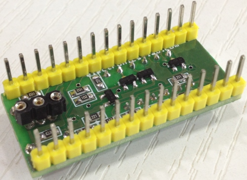
3D printers and other prototyping tools are making it easier and simpler to build prototypes and test ideas. Building circuit boards is fun but difficult. While you could do it at home with some etchant and some clear plastic, PCB printer hopes to make the entire process much faster and easier. The success of these tools make them necessary through the different domains of manufacturing.
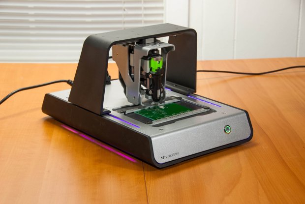
A desktop PCB printer?
Voltera V-One is a desktop PCB printer that can make two layer circuit boards. It can print onto the standard FR4 boards, and also place small components on the board.
In fact, the Voltera V-One uses a gantry system, similar to a 3D printer or CNC mill, to move accurately in the X, Y, and Z dimensions. The base of the V-One also heats up like a skillet to bake the conductive ink into place and to reflow SMD parts.
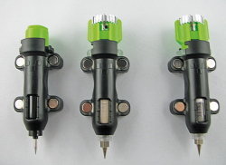
V-One has three tool heads that attach magnetically:
a probe to measure the blank PCB and feature locations
a conductive ink dispenser that draws the circuit traces and part pads
a solder paste dispenser that applies solder to pads for surface-mount devices (SMD)
This video shows a brief about how Voltera works, it produced a printed circuit board of a prototype GPS module in about half an hour.
Voltera V-One is available for $3,500. You can get more information about V-One and its specifications by visiting the official website.
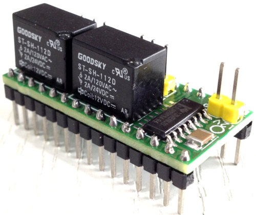
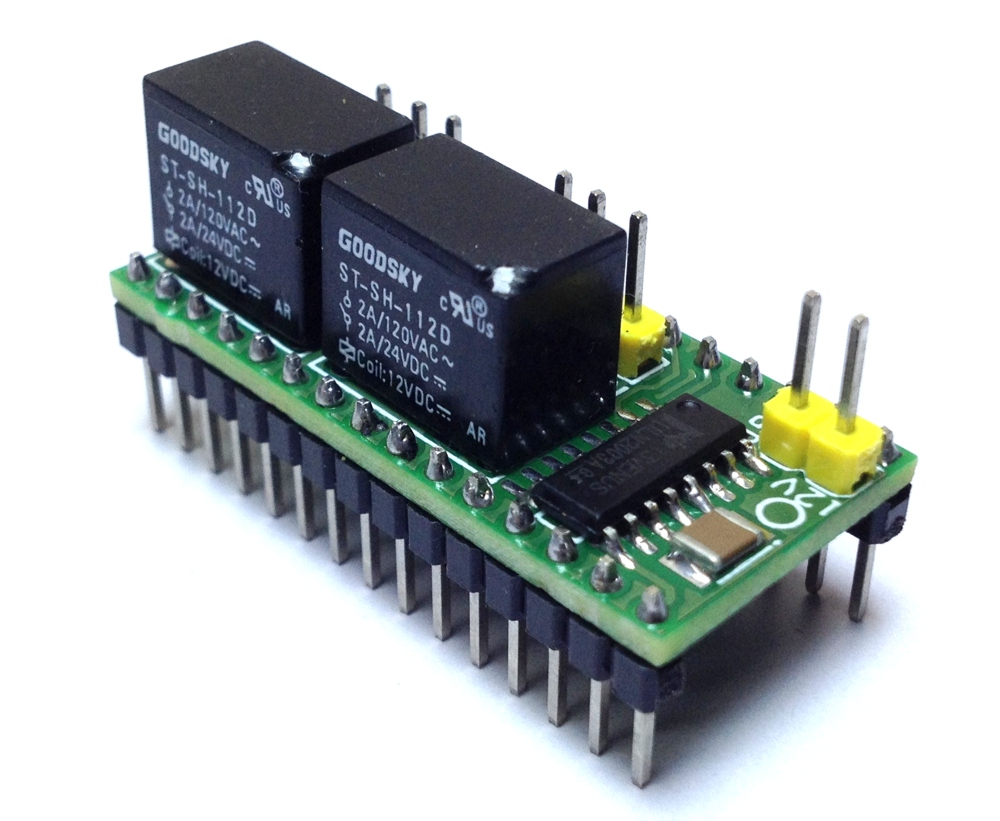
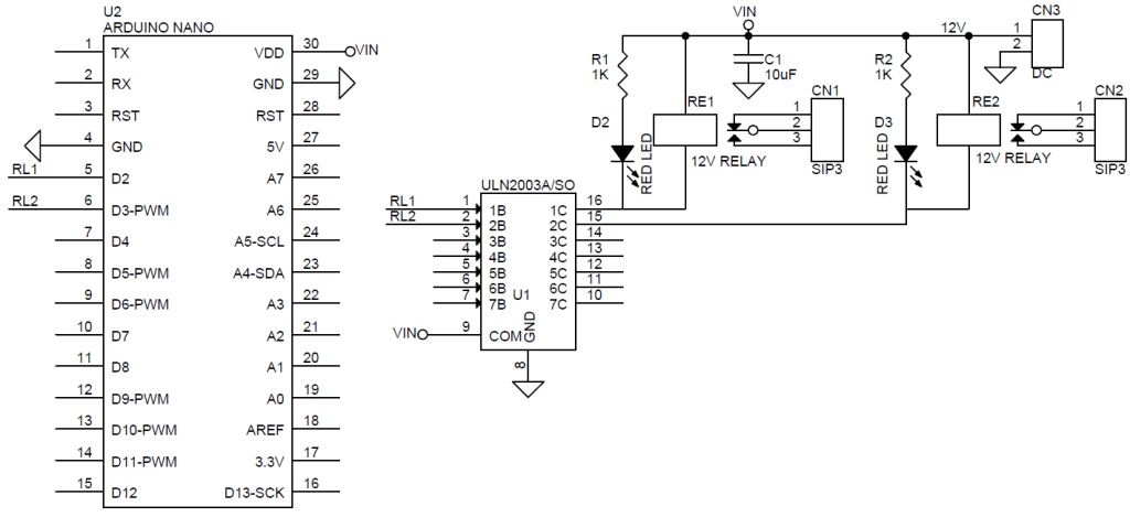
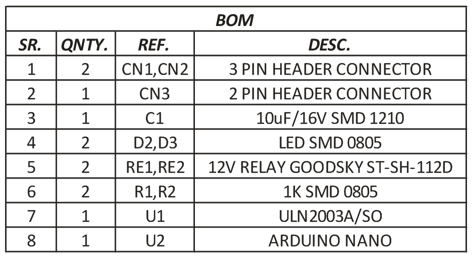
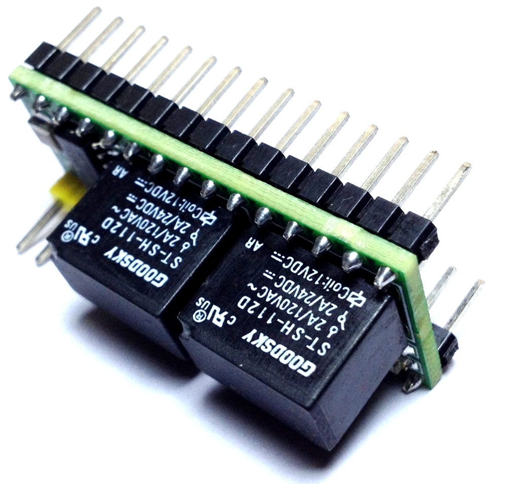
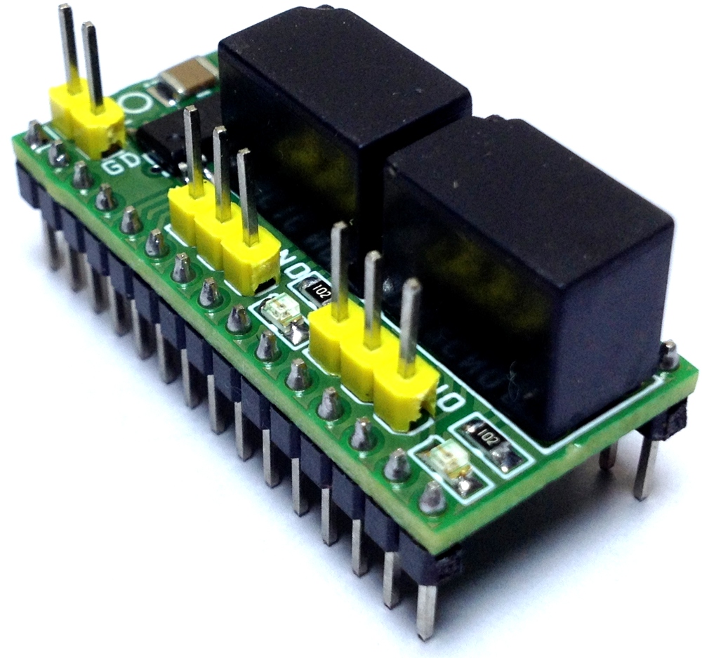
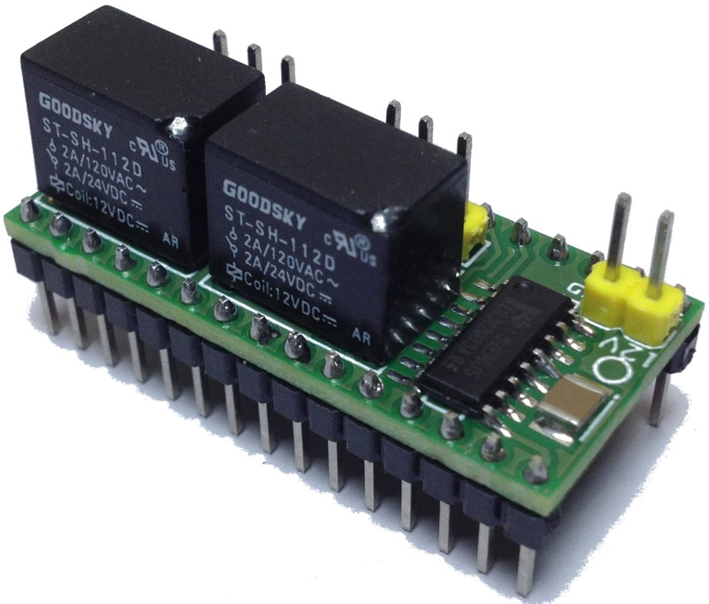
2 Channel Mini easy to use Relay shield for Arduino Nano consists of ULN2003 IC and 2 Mini 12V Relays with NO/NC contacts of 2A-24V Load Capacity. ULN2003 used as Relay coil driver. Relay can be controlled from D3 and D4 of Arduino Nano. Three pin Header Connector CN1 and CN2 provided to connect the Load. Relay has normally open and normally closed contacts with 2A and 24V capacity and also can handle 120V AC but it’s not advisable. CN2 supply input 12V DC. LED D2 and D3 are the output LEDs.
2 Channel Mini easy to use Relay shield for Arduino Nano consists of ULN2003 IC and 2 Mini 12V Relays with NO/NC contacts of 2A-24V Load Capacity. ULN2003 used as Relay coil driver. Relay can be controlled from D3 and D4 of Arduino Nano. Three-pin Header Connector CN1 and CN2 provided to connect the Load. Relay has normally open and normally closed contacts with 2A and 24V capacity and also can handle 120V AC but it’s not advisable. CN2 supply input 12V DC. LED D2 and D3 are the output LEDs.
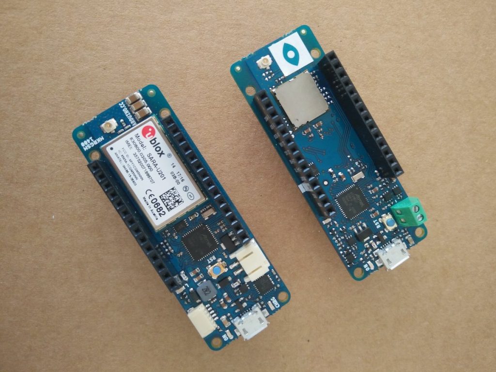
Arduino has introduced a pair of new IoT boards with embedded LoRa and GSM capabilities.
The Arduino MKR WAN 1300 and MKR GSM 1400 are designed to offer a practical and cost-effective solution for developers, makers and enterprises, enabling them to quickly add connectivity to their projects and ease the development of battery-powered IoT edge applications.
Both of the highly compact boards measure just 67.64 x 25mm, together with low power consumption, making them an ideal choice for emerging battery-powered IoT edge devices in the MKR form factor for applications such as environmental monitoring, tracking, agriculture, energy monitoring and home automation.
Introducing the Arduino MKR WAN 1300 and MKR GSM 1400 – [Link]
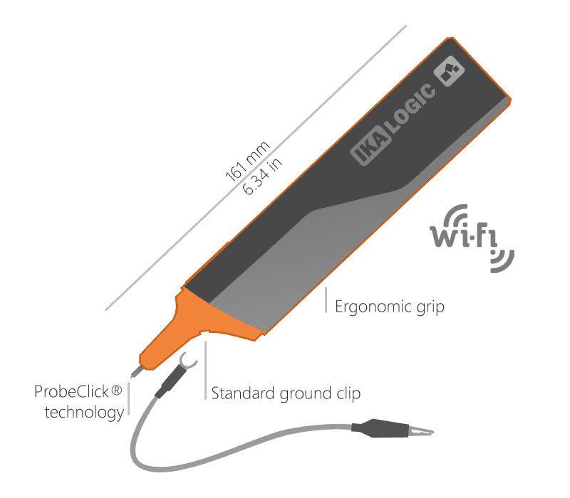
IkaScope is a wireless oscilloscope probe that allows to observe the change of electrical signals over time. The probe is a handheld device, portable and fits perfectly in the hand and pocket. By using high-speed Wi-Fi connection, IkaScope wireless oscilloscope probe communicates with laptop, tablet or smartphone to share the acquired data on the screen. The IkaScope wireless oscilloscope probe is compatible with the most popular mobile and desktop operating systems. The probe has a 200 MSPs ADC, Spartan 3 FPGA and adequate battery capacity (450 mAh). Energy saving settings and downtime moments manage the energy efficiency. The probe comes with a ground clip and a USB charging cable. Especially relevant is the patented ProbeClick technology of IkaScope: all electronic circuits are powered only when the the probe is pressed (figure 1). The probe tip is also used to start the data acquisition. ProbeClick technology allows to save power and measure without remembering to press the run / stop button of a classic oscilloscope.
Figure 1: IkaScope wireless oscilloscope probe
The probe technology and user interface
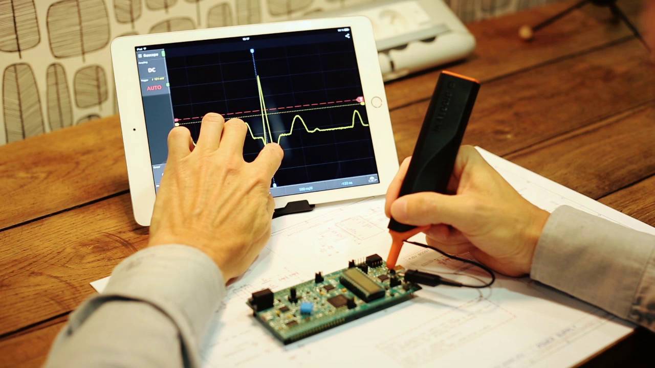
ProbeClick represents a simple innovative mechanism to manage the data acquisition by probe tip. Simply by pressing the probe, the device starts data capturing and streaming process on the screen using the wi-fi connection. In addition, by releasing the probe, the acquisition stops and automatically the data is available in the storage/cloud (figure 2). IkaScope application is the user interface to capture, measure and analyze analog signals. From the download page you can download the latest version of IkaScope for your prefered Desktop OS.
Figure 2: IkaScope during a testing process
IkaScope can be configured as a wireless hotspot. It will remember access points and will connect instantly without having to enter your login password. Moreover, IkaScope application has a share button at the top left of the screen. Just click on it to share a screenshot of the measurement.
General specifications
Model name: WS200.
Communication: WiFi 802.11 b/g/n/e/i 2.4GHz.
Connection: Access Point or Station.
Battery charging connector: Micro USB.
Input contact: ProbeClick.
Operating Temperature: 10°C to 35°C.
Altitude < 2000m.
Protection Input level: Sample test voltage: 253 VAC 1 min.
Input to charging port isolation: Saple test voltage: 1100 VAC 1 min.
Battery: Built in Lithium / 420mAh
Application compatibility: Windows / Mac / Linux / Android / iOS.
Measurement specifications
Max sample rate: 200MSps.
Analog Bandwidth(-3dB compression): 30MHz at -3dB.
Input Voltage: +/-40V range CAT1.
Galvanic isolation: Between Input and Charging port.
Coupling: AC (true) / DC.
Input Impedance: 1MOhm || 14pF.
Voltage resolution: 100mV/div up to 10V/div.
Max Trace refresh rate: 250 FPS.
Sample resolution: 8 bits.
Analog Offset range: +/-20V to +/-40V.
Memory depth: 4K Points (4 x 1000 points burst buffers).