

SyncChannelBlog @ oshpark.com writes:
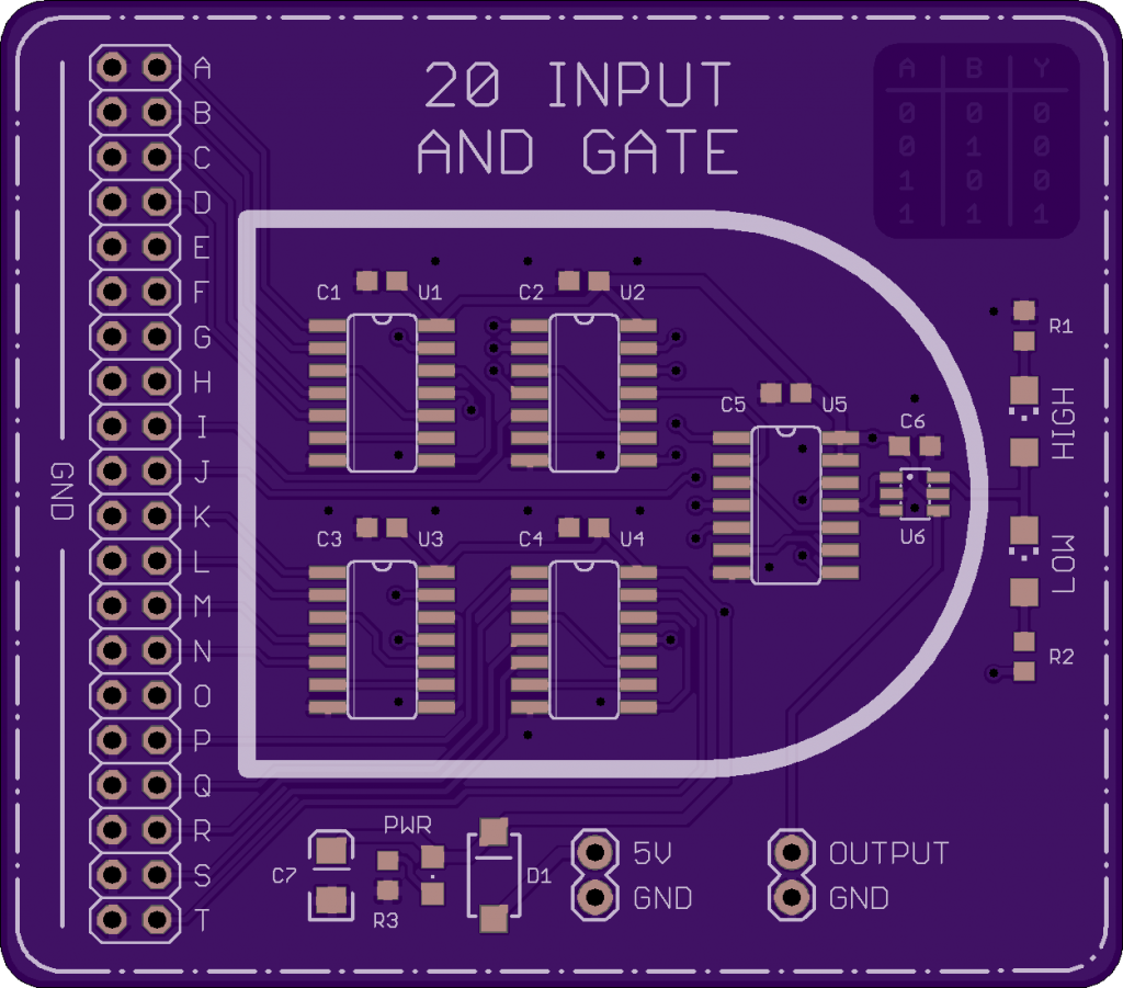
What to do when you have a partial reel of 74AHCT08 chips burning a hole in your pocket? Design a 20 Input AND gate of course.
20 Input AND Gate – [Link]
SyncChannelBlog @ oshpark.com writes:
What to do when you have a partial reel of 74AHCT08 chips burning a hole in your pocket? Design a 20 Input AND gate of course.
20 Input AND Gate – [Link]
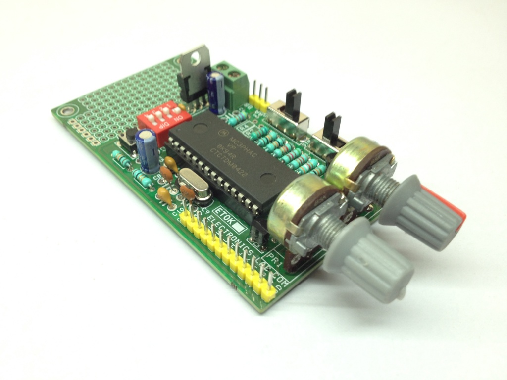
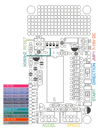
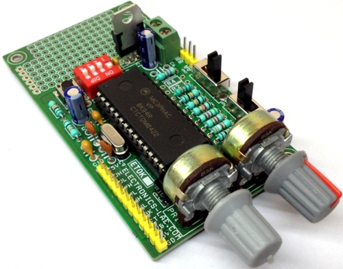
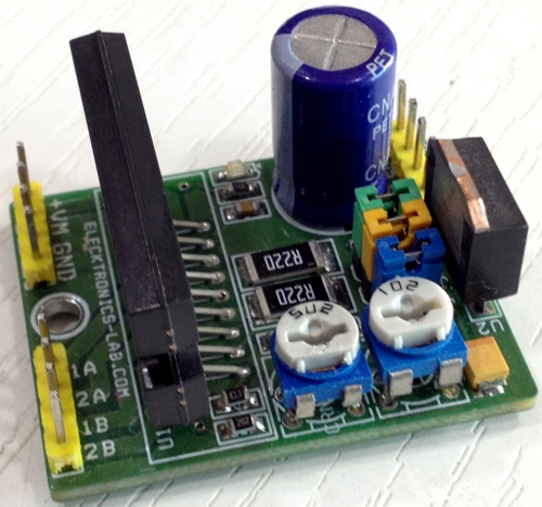
This project made using MC3PHAC from NXP Semiconductor. The project generates 6 PWM signals for 3 Phase AC Motor controller. It’s very easy to make professional VFD combining with Intelligent Power Module (IPM) or 3 Phase IGBT/MOSFET with Gate driver. The board provides 6 PWM signals for the IPM or IGBT Inverter and also brake signal. Also this board works in stand-alone mode and doesn’t require any software programming/coding.
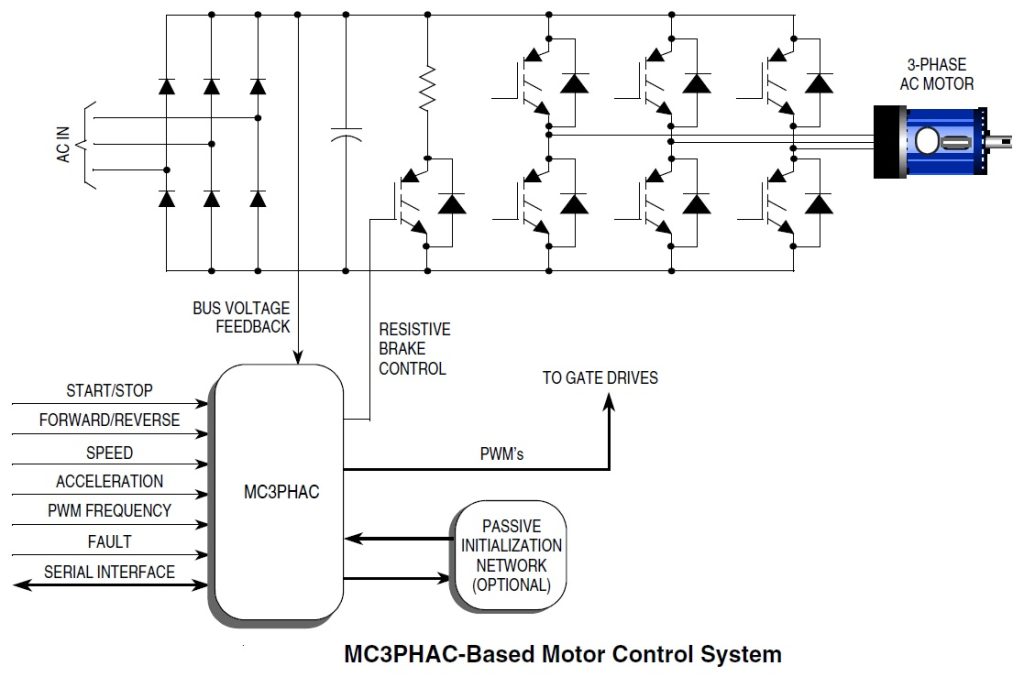
The MC3PHAC is a high-performance monolithic intelligent motor controller designed specifically to meet the requirements for low-cost, variable-speed, 3-phase ac motor control systems. The device is adaptable and configurable, based on its environment. It contains all of the active functions required to implement the control portion of an open loop, 3-phase ac motor drive. One of the unique aspects of this board is that although it is adaptable and configurable based on its environment, it does not require any software development. This makes the MC3PHAC a perfect fit for customer applications requiring ac motor control but with limited or no software resources available.
Included in the MC3PHAC are protective features consisting of dc bus voltage monitoring and a system fault input that will immediately disable the PWM module upon detection of a system fault.
3 Phase AC Motor Controller – [Link]
This project made using MC3PHAC from NXP Semiconductor. The project generates 6 PWM signals for 3 Phase AC Motor controller. It’s very easy to make professional VFD combining with Intelligent Power Module (IPM) or 3 Phase IGBT/MOSFET with Gate driver. The board provides 6 PWM signals for the IPM or IGBT Inverter and also brake signal. Also this board works in stand-alone mode and doesn’t require any software programming/coding.
The MC3PHAC is a high-performance monolithic intelligent motor controller designed specifically to meet the requirements for low-cost, variable-speed, 3-phase ac motor control systems. The device is adaptable and configurable, based on its environment. It contains all of the active functions required to implement the control portion of an open loop, 3-phase ac motor drive. One of the unique aspects of this board is that although it is adaptable and configurable based on its environment, it does not require any software development. This makes the MC3PHAC a perfect fit for customer applications requiring ac motor control but with limited or no software resources available.
Included in the MC3PHAC are protective features consisting of dc bus voltage monitoring and a system fault input that will immediately disable the PWM module upon detection of a system fault.
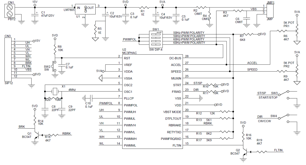
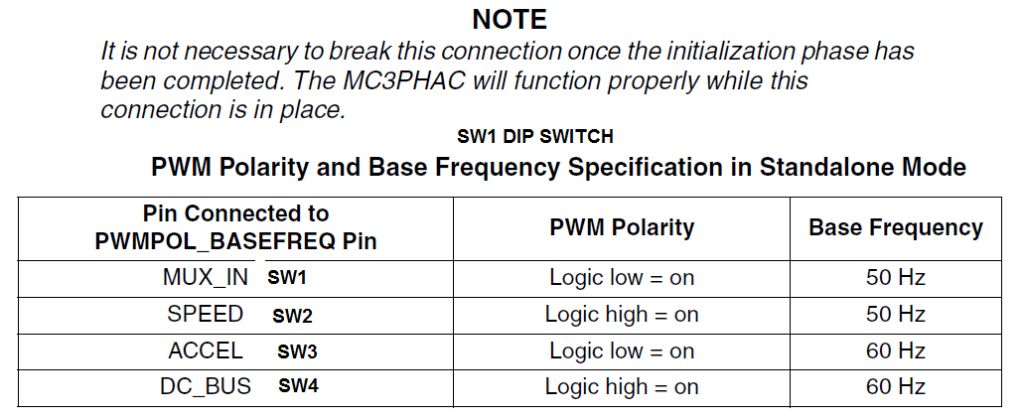
All outputs are TTL signals, Input supply 5-15V DC, DC Bus voltage should be between 1.75V-4.75V, Dip switch provided to set the motor frequency 60 or 50 Hz, jumpers also helps to set the polarity of the output PWM Active Low or Active High and this helps to use this board with any kind of IPM modules since output can be set active low or high. Potentiometer PR2 helps to adjust motor speed. Refer to datasheet of the IC to change base frequency, PWM Dead Time, other possible parameters.
Speed Control — the synchronous motor frequency can be specified in real time to be any value from 1 Hz to 128 Hz by adjusting the PR2 potentiometer. The scaling factor is 25.6 Hz per volt. The SPEED pin is processed by a 24-bit digital filter to enhance the speed stability in noisy environments.
Acceleration Control — Motor acceleration can be specified in real time to be in the range from 0.5 Hz/second, ranging to 128 Hz/second, by adjusting the PR1 potentiometer. The scaling factor is 25.6 Hz/second per volt.
Fault Protection: The MC3PHAC supports an elaborate range of fault protection and prevention features. If a fault does occur, the MC3PHAC immediately disables the PWMs and waits until the fault condition is cleared before starting a timer to re-enable the PWMs. Refer to the graph in Figure 10 for the resistance value versus retry time from data sheet of the IC. Figure 10 assumes a 6.8 kΩ pull up resistor. In standalone mode, this timeout interval is specified during the initialization phase by supplying a voltage to the MUX_IN pin while the RETRY_TxD pin is being driven low. In this way, the retry time can be specified from 1 to 60 seconds, with a scaling factor of 12 seconds per volt
External Fault Monitoring: The FAULTIN pin accepts a digital signal that indicates a fault has been detected via external monitoring circuitry. A high level on this input results in the PWMs being immediately disabled. Typical fault conditions might be a dc bus over voltage, bus over current, or over temperature. Once this input returns to a logic low level, the fault retry timer begins running, and PWMs are re-enabled after the programmed timeout value is reached. FLTIN input pin 9 of the connecter CN3 should be high to bring the fault pin low for normal operation.
Bus Voltage Integrity Monitoring ( Input Pin 10 of the CN3) The DC_BUS pin is monitored at a 5.3 kHz frequency (4.0 kHz when the PWM frequency is set to 15.9 kHz), and any voltage reading outside of an acceptable window constitutes a fault condition. In standalone mode, the window thresholds are fixed at 4.47 volts (128 percent of nominal), and 1.75 volts (50 percent of nominal), where nominal is defined to be 3.5 volts. Once the DC_BUS signal level returns to a value within the acceptable window, the fault retry timer begins running, and PWMs are re enabled after the programmed timeout value is reached. During power-up, it is possible that VDD could reach operating voltage before the dc bus capacitor charges up to its nominal value. When the dc bus integrity is checked, an under voltage would be detected and treated as a fault, with its associated timeout period. To prevent this, the MC3PHAC monitors the dc bus voltage during power-up in standalone mode, and waits until it is higher than the under voltage threshold before continuing. During this time, all MC3PHAC functions are suspended. Once this threshold is reached, the MC3PHAC will continue normally, with any further under voltage conditions treated as a fault.
Note : If dc bus voltage monitoring is not desired, a voltage of 3.5 volts ± 5 percent should be supplied to the DC_BUS pin. To do this Use following components, R2 Should be 3.3Kohms, R4 4K7 Ohms, C6 0.1uF and close jumper between pin1 and pin 2.
Regeneration Control — Regeneration is a process by which stored mechanical energy in the motor and load is transferred back into the drive electronics, usually as a result of an aggressive deceleration operation. In special cases where this process occurs frequently (for example, elevator motor control systems), it is economical to incorporate special features in the motor drive to allow this energy to be supplied back to the ac mains. However, for most low cost ac drives, this energy is stored in the dc bus capacitor by increasing its voltage. If this process is left unchecked, the dc bus voltage can rise to dangerous levels, which can destroy the bus capacitor or the transistors in the power inverter. The MC3PHAC incorporates two techniques to deal with regeneration before it becomes a problem.
Resistive Braking: The DC_BUS pin is monitored at a 5.3 kHz frequency (4.0 kHz when the PWM frequency is set to 15.9 kHz), and when the voltage reaches a certain threshold, the RBRAKE pin is driven high. This signal can be used to control a resistive brake placed across the dc bus capacitor, such that mechanical energy from the motor will be dissipated as heat in the resistor versus being stored as voltage on the capacitor. In standalone mode, the DC_BUS threshold required to assert the RBRAKE signal is fixed at 3.85 volts (110 percent of nominal) where nominal is defined to be 3.5 volts.
Selectable PWM Frequency: The MC3PHAC accommodates four discrete PWM frequencies and can be changed dynamically while the motor is running. This resistor can be a potentiometer or a fixed resistor in the range shown in Table In standalone mode, the PWM frequency is specified by applying a voltage to the MUX_IN pin while the PWM FREQ_RxD pin is being driven low. Table 4 from data sheet shows the required voltage levels on the MUX_IN pin and the associated PWM frequency for each voltage range.
Some target applications for the MC3PHAC include
Researchers at the University of Houston reported in the journal Nature Communications the discovery of a new design that significantly improves the development of a battery based on magnesium. Magnesium batteries are considered as safe resources of power supply – unlike traditional lithium-ion batteries. They are not flammable or subject to exploding – but their ability to store energy is very limited. But the latest discovery of the new design for the battery cathode drastically increases the storage capacity.
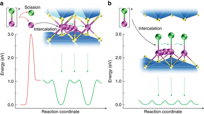
In order to make magnesium batteries, the magnesium-chloride bond must be broken before inserting magnesium into the host, and this is very hard to do. Hyun Deog Yoo, the first author of the paper, said,
First of all, it is very difficult to break magnesium-chloride bonds. More than that, magnesium ions produced in that way move extremely slowly in the host. That altogether lowers the battery’s efficiency.
The new battery technology stores energy by inserting magnesium monochloride into titanium disulfide, which acts as a host. By keeping the magnesium-chloride bond intact, the cathode showed much faster diffusion than traditional magnesium batteries.
The researchers managed to achieve a storage capacity density of 400 mAh/g – a quadruple increase compared with 100 mAh/g for earlier magnesium batteries. This achievement even overpowered the 200 mAh/g cathode capacity of commercially available lithium-ion batteries. Yoo, who is also the head investigator with the Texas Center for Superconductivity at UH, confirmed this fact.
The cell voltage of a magnesium cell is only 1V which is significantly less than a lithium-ion battery which has 3.7V cell voltage. Higher cell voltage and high cathode capacity made Li-ion batteries the standard. Li-ion batteries suffer from an internal structural breach, known as dendrite growth what makes them catch fire. Being an earth-abundant material, magnesium is less expensive than lithium and is not prone to dendrite growth.
The magnesium monochloride molecules are too large to be inserted into the titanium disulfide using conventional methods. The trick they developed is to expand the titanium disulfide to allow magnesium chloride to be inserted rather than breaking the magnesium-chloride bonds and inserting the magnesium alone. Retaining the magnesium-chloride bond doubled the charge the cathode could store. Yoo said,
We hope this is a general strategy. Inserting various polyatomic ions in higher voltage hosts, we eventually aim to create higher-energy batteries at a lower price, especially for electric vehicles.
Canonical, the company behind Ubuntu, announced recently that its IoT OS, Ubuntu Core, is available on the Raspberry Pi Compute Module 3 – the general-purpose compute product from the Raspberry Pi Foundation. This OS, the smallest Ubuntu ever, is the perfect host operating system for IoT devices and large-scale cloud container deployments. Actually, the Raspberry Pi Compute Module 3 (CM3), is a micro-version of the Raspberry Pi 3. With its new features, it provides a simple and affordable single board computer.
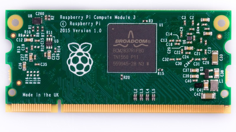
In fact, this module is based on the Raspberry Pi 3 hardware, providing twice the RAM and roughly 10x the CPU performance of the original Module, launched in 2014. Even though CM3 is replacing the original Compute Module, but CM1 is still compatible with the new Compute Module IO Board V3, and remains available for sale.
CM3 takes care of the complexity of routing out the pins, the high speed RAM interface and core power supply. Also, it allows a simple carrier board to provide what is necessary for external interfaces and form factor. The module uses a standard DDR2 SODIMM form factor, sockets by several manufacturers, are easily available, and are inexpensive.
As a vision for Canonical, The CM3 with Ubuntu Core allows developers to create new IoT products and devices. As well as offering a potentially smaller and more efficient replacement for some devices that contain larger Raspberry Pi boards.
“Gaining official support for Ubuntu Core is highly significant for our Compute Module 3. It opens up a huge community of developers keen to leverage Ubuntu’s particular advantages in the IoT world; its resource-efficient footprint, versatility, and industry leading security benefits,” says Eben Upton, CEO at Raspberry Pi.
Finally, more comprehensive information on the Compute Modules is available in the this hardware documentation, and includes a datasheet and schematics. In addition, you can check this step-by-step tutorial to install Core OS on your Compute Module 3 by Ubuntu Developer.
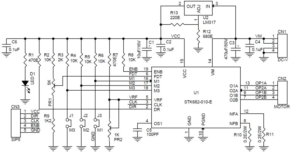
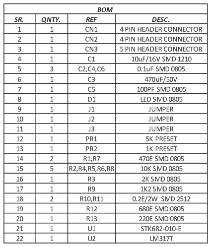
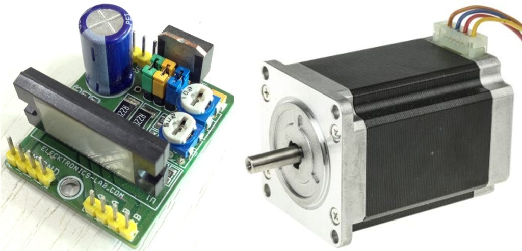
2 Phase stepping motor driver is a tiny board based on STK682-010 hybrid IC from ON semiconductor and it can deliver current up to 2.5Amp and has supply up to 32V DC. It has multiple micro-stepping: Full step, 1/2th Step, 1/4th Step, 1/8th Step, 1/16th Step, 1/32th Step, 1/64th Step, 1/128th Step. PR1 trimmer potentiometer is provided to set the decay, 3.5V Slow Decay, 1.1V to 3.1V Mixed Decay, 0.8V-1V Fast Decay, and PR2 Trimmer Potentiometer provided to set the Current.
Features
2.5A 2Phase Micro-Stepping Stepper Motor Driver – [Link]
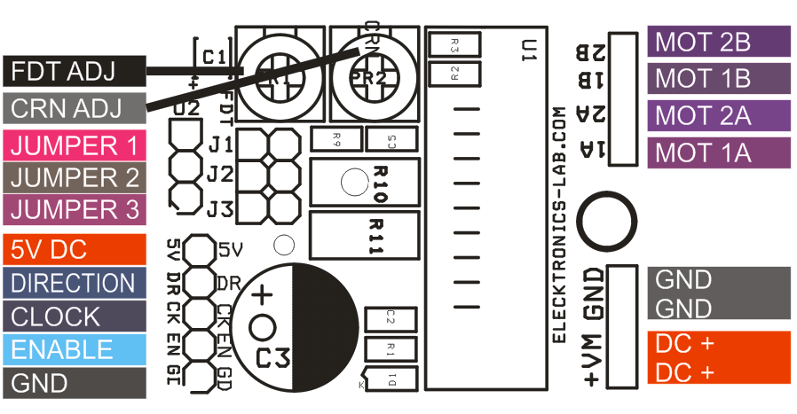
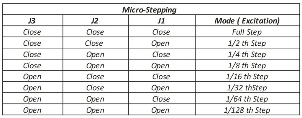
2 Phase stepping motor driver is a tiny board based on STK682-010 hybrid IC from ON semiconductor and it can deliver current up to 2.5Amp and has supply up to 32V DC. It has multiple micro-stepping: Full step, 1/2th Step, 1/4th Step, 1/8th Step, 1/16th Step, 1/32th Step, 1/64th Step, 1/128th Step. PR1 trimmer potentiometer is provided to set the decay, 3.5V Slow Decay, 1.1V to 3.1V Mixed Decay, 0.8V-1V Fast Decay, and PR2 Trimmer Potentiometer provided to set the Current. Chopping frequency set to 83.3 KHz with the help of capacitor C5 100PF. Micro-Stepping can be set with the help of jumper J1, J2, J3. U2 provides 5V DC for logic circuit. All input signals can be feed through CN3. This board is default enabled since the enable pin has pull-up and you may short enable pin to GND to disable the board. The board required Step pulse and direction signal to operate the motor. IC has built in automatic half current functions to reduce the vibrations & current while motor is in static mode. Refer to table for Micro-Stepping setup. IC requires heat sink.
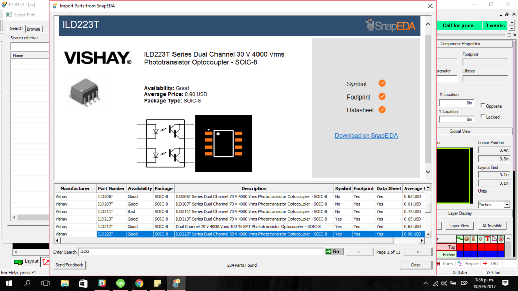
Designers can now search SnapEDA’s vast component library directly in PCB123
MULINO, OR and SAN FRANCISCO, CA (September 13, 2017) — Today, Sunstone Circuits, creators of the free PCB design tool, PCB123, and SnapEDA, the Internet’s first parts library for circuit board design, are launching a new integration that allows designers to search for digital models directly inside the PCB123 design environment.
Designers have traditionally wasted days creating digital models for their designs. This process is tedious, time-consuming, and error-prone. With today’s release of PCB123 Version 5.6, designers can now search and download free, cloud-based symbols and footprints directly during design capture and layout, significantly boosting design productivity.
“For forty years, PCB designers have frittered away countless hours defining parts because there simply wasn’t a workable, affordable source for accurate, ready-made parts. In fact, surveys show that most professional designers spend an average of 30-35% of their design time just making new parts definitions before they can even get started,” said Nolan Johnson, CAD & EDA Product Marketing Manager at Sunstone Circuits.
“SnapEDA has disrupted that dynamic in an easy-to-use, no-cost utility, and PCB123 is proud to be bringing true in-tool integration of SnapEDA’s parts search functions to our loyal users – in a free PCB CAD tool, no less,” Johnson added.
PCB123 is a free, full-function PCB CAD tool, comprised of a schematic editor, physical layout editor, 3-dimensional mechanical previews, and BOM editor. By augmenting the tool with cloud-based libraries, designers will get real-time access to new symbols & footprints added to SnapEDA’s catalog, as well the ability to request parts they need for their designs with InstaPart, the company’s popular 24 hour parts request service.
“PCB123 has just released the industry’s first pre-installed integration of a cloud-based parts library. Their impressive solution will benefit PCB designers with access to vetted parts models that will shave days off design time, and benefit the world through faster innovation,” said Natasha Baker, Founder & CEO of SnapEDA.
All new models created by SnapEDA conform to the latest IPC standards (IPC-7351B) and are vetted with its patent-pending verification technology. Design content is available for millions of electronic components, enabled by SnapEDA’s proprietary, automated library creation, translation, and verification technology.
Microchip introduced a new 64Mbit Serial Quad I/O™ memory device—SST26WF064C with proprietary SuperFlash® technology. The SST26WF064C writes with a single power supply of 1.65-1.95V and significantly lower power consumption. This makes it ideal for wireless, mobile, and battery-powered applications.

This 64Mbit memory device also features DTR or Dual Transfer Rate technology. DTR lets the user access data of the chip on both rising and falling edges of the clock, reducing overall data access time and power consumption significantly. The SST26WF064C utilizes a 4-bit multiplexed I/O serial interface to boost performance while maintaining the tiny form factor of standard serial flash devices.
Microchip’s high-performance CMOS SuperFlash technology provides the fastest chip erase time, consequently, reduces overall power consumption. It also improves performance and reliability of the memory chip. The SST26WF064C’s typical chip-erase time is 35-50 milliseconds, where other chips take nearly 30 seconds to be completely erased.
This chip combines a hardware controlled RESET function which is not present in common flash chips available in the market due to their limited pin count. In SST26WF064C, the user can program the HOLD pin to use for the RESET function. This feature lets the host microcontroller to reset the chip by sending a pulse to it.
SST26WF064C supports full command-set compatibility with traditional Serial Peripheral Interface (SPI) protocol. Operating at frequencies reaching 104 MHz, the SST26WF064C enables minimum latency execute-in-place (XIP) capability without the need for code shadowing on a SRAM. To learn about code shadowing, read this article.
The key features of the SST26WF064C are:
To learn more about this memory chip or to purchase some, visit http://www.microchip.com/wwwproducts/en/SST26WF064C.
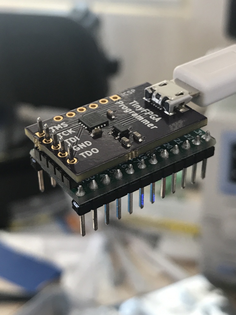
A dirt cheap open hardware USB-JTAG board designed to program TinyFPGA A1 and A2 boards. by Luke Valenty @ hackaday.io:
One of the goals of the TinyFPGA boards is to make FPGAs cheaper to use. The #TinyFPGA A-Series boards are the first TinyFPGA boards and are designed to be the least expensive. As such, they do not include a built-in USB interface as that would increase the cost and complexity too much. Instead they rely on JTAG programmers.
TinyFPGA Programmer – [Link]


