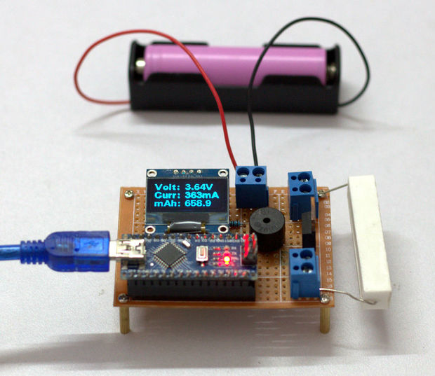
I have salvaged so many old lap-top batteries ( 18650 ) to reuse them in my solar projects.It is very difficult to identify the good cells in battery pack.Earlier in one of my Power Bank Instructable I have told, how to identify good cells by measuring their voltages, but this method is not at all reliable.So I really wanted a way to measure each cell exact capacity instead of their voltages.
In this Arduino project video, educ8s.tv is going to build a simple FM Radio using the TEA5767 module with a Nokia LCD display:
In this video, we are going to build this. A simple FM Radio receiver on a breadboard. Let’s listen to it for a few seconds … As you can see the radio is working fine and we can hear some music coming out of it. I am transmitting some YouTube safe tracks using this inexpensive FM transmitter at this frequency. I am using the Nokia 5110 LCD display, to display the selected frequency, the signal strength, and a stereo icon if we are receiving stereo sound. The brains of the project are the small and inexpensive Arduino Nano. We can control the volume of the speaker using this potentiometer, and we can change the Radio frequency using this potentiometer. It is a fascinating project and relatively easy to build. Let’s see how to build it.
Arduino FM Radio Project with TEA5767 Radio Module and a Nokia 5110 LCD Display – [Link]
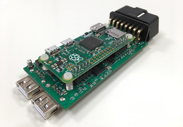
What if your car was intelligent like KITT in the 80’s TV show Knight Rider? With AutoPi all cars become intelligent and can have eyes, ears and a voice.
Until now all functionality and data from cars have belonged only to the manufacturers. With AutoPi the car owners can, as a cooperating community, take control over their own vehicles and data without having to be an engineer.
AutoPi.io is a Danish startup company and they have just launched their open Internet-of-Things platform for cars. It is the first extendable maker platform for cars, built on the revolutionary Raspberry Pi mini computer.
In less than 24 hours, their Kickstarter campaign has raised more than $20.000:
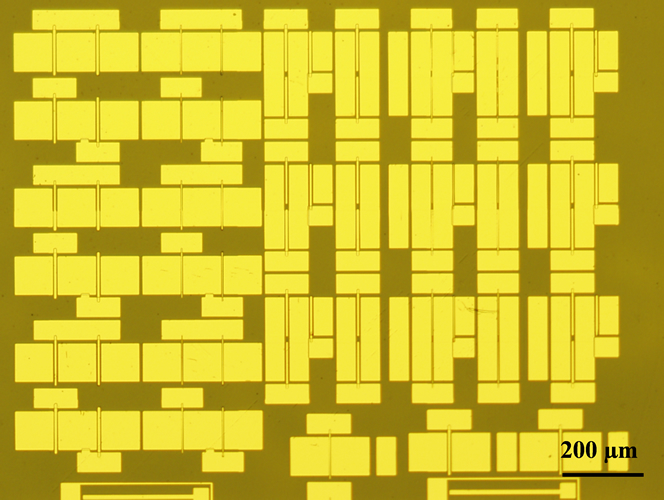
A research group at Japan’s National Institute for Materials Science (NIMS) has developed logic circuits equipped with diamond-based metal-oxide-semiconductor field-effect-transistors (MOSFETs) at two different operation modes – a first step toward the development of diamond integrated circuits operational under extreme environments.
Is Diamond Suitable for this?
In fact, diamond has high carrier mobility, a high breakdown electric field and high thermal conductivity. Therefore, it is a promising material to use in the development of current switches and integrated circuits. Specifically to operate stably at high-temperature, high-frequency, and high-power. However, it had been difficult to enable diamond-based MOSFETs to control the polarity of the threshold voltage. In addition, fabricating MOSFETs of two different modes on the same substrate was a challenge. The modes are: a depletion mode (D mode) and an enhancement mode (E mode).
Thus, the research group has successfully developed a logic circuit equipped with modes. Thanks to threshold control technique that allowed them create hydrogenated diamond NOT and NOR logic circuits composed of D-mode and E-mode MOSFETs.
Micrograph of a fabricated logic circuit equipped with diamond-based transistors
This study was published in the online version of IEEE Electron Device Letters and it is available at the IEEE Electron Digital Library website. Also, check the official announcement for more details.
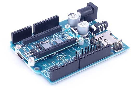
Sony has recently launched one of its new products, Spritzer! Spritzer is an Arduino-compatible board for IoT applications that has built-in GPS, audio codec, and low power consumption.
While it is Arduino-compatible, the board allows any developer to easily start app development using the free Arduino IDE and an ordinary USB cable. In fact, the board features a processing chip with a unique combination of low power consumption and a rapid clock speed of 156MHz. Thus, it is extremely versatile and it can be deployed for a vast range of use cases.
For the first time, the company demonstrated the board at Tokyo Maker Faire last month with a drone utilizing the GPS and the 6-axis sensor support, a smart speaker utilizing the audio functions, a self-driving line-tracing miniature car, and a low-power smart sensing IoT camera using the camera interface of Spritzer.
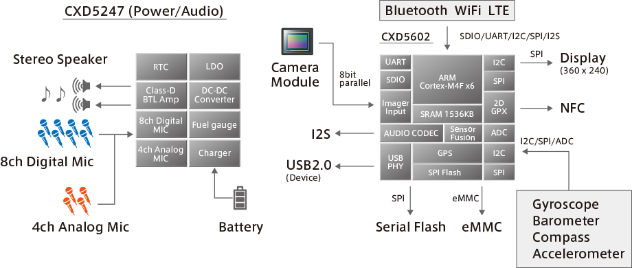
Sony Spritzer specifications
MCU – Sony CDX5602 ARM Cortex-M4F ×6 micro-controller clocked at up to 156 MHz with 1.5MB SRAM
Storage – 8MB Flash Memory, micro SD card
GNSS – GPS, GLONASS, supported
Audio – 3.5mm audio jack
Expansion I/Os
Digital I/O Pins – SPI, I2C, UART, PWM ×4 (3.3V)
Analog Pins – 6ch (3.3V range)
Audio I/O – 8ch Digital MICs or 4ch Analog MICs, Stereo Speaker, I2S, CXD5247 audio codec with 192 kHz/24bit High-Resolution audio
2x camera interfaces
USB – 1x micro USB port for programming
Spritzer Block Diagram
“You’ll have to connect external module to get Bluetooth, WiFi, and LTE, a display up to 360×240 resolution can be used via SPI, all sort of sensors can be connected via the expansion header, the board is suitable for microphone arrays, and it can be powered by batteries thanks to a charger circuit and fuel gauge inside CXD5247 audio codec / PMU chip.” – CNXSoft
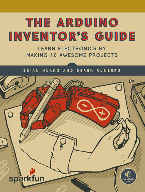
Are you looking for Arduino tutorials? Already over-whelmed by the guides and videos available on the internet? Sparkfun is making Arduino and electronics easier for you with its new book ” The Arduino Inventor’s Guide”!
First of all, the authors of this book , Brian Huang and Derek Runberg, are both working in the department of Education at SparkFun Electronics. Since they are experienced in electronics and educating engineering in schools, they are working towards making electronics easy and fun.
In fact, this 10-project guide is a project-packed introduction to building and coding with Arduino microcontroller. With each hands-on project, total beginners learn useful electronics and coding skills while building an interactive gadgets. Accordingly, this guide is within the introductory-level educational series introduced by No Starch Press and Sparkfun.
“We wanted to share the magic that happens when you build something interactive with electronics,” says Huang. “The goal is to teach real, valuable hardware skills, one project at a time,” adds Runberg.
Content of the book
Introduction
Electronics Primer 101 electronics
Project 1: Getting Started with Arduino
Blinking an LED
Project 2: A Stoplight for Your House
A miniature traffic light
Project 3: The Nine-Pixel Animation Machine
An LED screen that displays animated patterns and shapes
Project 4: Reaction Timer
A fast-paced button-smashing game to test your reflexes
Project 5: A Color-Mixing Night-Light
A light-sensitive, color-changing night-light
Project 6: Balance Beam
A challenging ball-balancing game
Project 7: Tiny Desktop Greenhouse
A temperature-sensing mini greenhouse with an automated fan and vent
Project 8: Drawbot, the Robotic Artist
A motorized robot that you can control
Project 9: Drag Race Timer
A racing timer for toy cars
Project 10: Tiny Electric Piano
A tiny electric piano that you can actually play!
Appendix: More Electronics Know-How
Reviews
“The Arduino Inventor’s Guide will appeal to the gadget freak as well as those who like to put their own spin on things.” —Microcontroller Tips
“This is probably the best Arduino starter book out there! I highly recommend it for every library and classroom.” —Sequential Tart
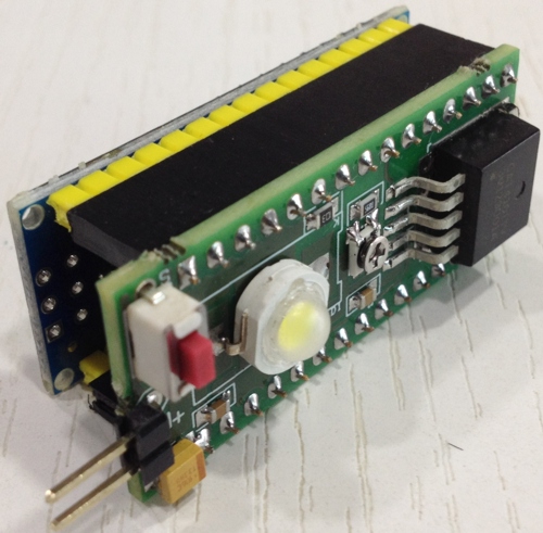
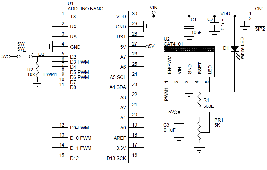
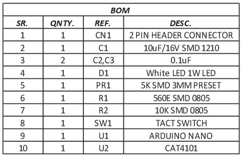
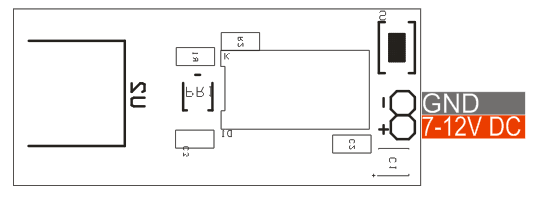
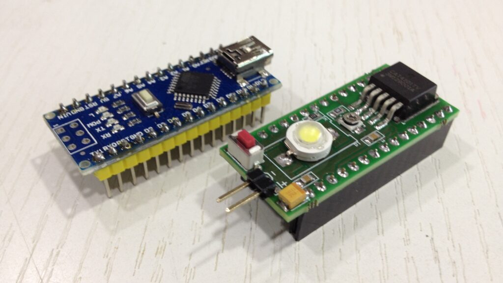
1A Constant current LED driver shield for Arduino Nano has been designed for verity of LED related applications. The shield provides accurate LED current sink to regulate LED current in a string of LEDs or single LED. The LED current is mirrored from the current flowing from the RSET Preset PR1. On board 1W LED is used for testing purpose. External high Wattage LED or multiple LED string can be connected by pulling two wires from the PCB and this shield fit directly on back side of Arduino Nano. Shield also has on board tactile switch connected to Digital D2 pin using pull down resistor if required for any application. On board preset helps to set the maximum constant current. PWM input pin connected to Digital pin D6 of Nano to control the LED intensity. Example code FADE-IN/FADEOUT helps to test the shield.
1Amp Constant Current LED Driver Shield for Arduino Nano – [Link]
1A Constant current LED driver shield for Arduino Nano has been designed for verity of LED related applications. The shield provides accurate LED current sink to regulate LED current in a string of LEDs or single LED. The LED current is mirrored from the current flowing from the RSET Preset PR1. On board 1W LED is used for testing purpose. External high Wattage LED or multiple LED string can be connected by pulling two wires from the PCB and this shield fit directly on back side of Arduino Nano. Shield also has on board tactile switch connected to Digital D2 pin using pull down resistor if required for any application. On board preset helps to set the maximum constant current. PWM input pin connected to Digital pin D6 of Nano to control the LED intensity. Example code FADE-IN/FADEOUT helps to test the shield.
The board built using CAT4101 IC from ON Semiconductor. The CAT4101 is a constant−current sink driving a string of high−brightness LEDs up to 1 A with very low dropout of 0.5 V at full load. It requires no inductor, provides a low noise operation and minimizes the number of external components. The LED current is set by an external Trimmer preset PR1 connected to the RSET pin. The LED pin is compatible with high voltage up to 12 V, allowing the driving of long strings of LEDs. The device ensures an accurate and regulated current in the LEDs independent of supply and LED forward voltage variation. The PWM/EN input allows the device shutdown and the LED brightness adjustment by using an external pulse width modulation (PWM) signal coming from Arduino Nano D6 pin. The driver features a thermal shutdown protection that becomes active whenever the die temperature exceeds 150°C.
PWM Duty Cycle and Frequency
Accurate linear dimming is compatible with PWM frequencies from 100 Hz to 5 kHz for PWM duty cycle
down to 1%. PWM frequencies up to 50 kHz can be supported for duty cycles greater than 10%.When performing a combination of low frequencies and small duty cycles, the device may enter shutdown mode. This has no effect on the dimming accuracy, because the turn−on time TPS is very short, in the range of 1s. To ensure that PWM pulses are recognized, pulse width low time TLO should be longer the 1s. The CAT4101 enters a “zero current” shutdown mode after a 5 ms delay (typical) when EN/PWM is held low.
Features
Supply 7-12V DC
Load Current 1A Max
Constant Current adjustable Up To 1A
High Resolution PWM Dimming
On Board Trimmer Potentiometer to set the constant Current
Nano Digital Pin D6 Connected to PWM of the CAT4101 IC
Nano Digital Pin D2 Connected to Tact Switch using Pull Down
When PR1 Trimmer Minimum its set to 1A current, @ 1.5K Ohms set to 385mA
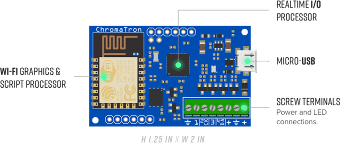
Chromatron is an open source Wifi pixel controller designed to make LED pixel projects easy and fun.
Hi, I’m Jeremy! I’ve designed a toolkit for making art with LED pixel strips, and I’d like to share it with you! Chromatron takes custom designed hardware and feature-packed firmware, sprinkles it with some Python, and serves up a delicious new platform to help you transform your world into a psychedelic dreamscape.
Sanket @ octopart.com tipped us with his latest blog post about voltage regulators and how to select them.
All electronics projects need power. Power can come from either stored energy in a battery, or directly from mains AC voltage or DC power from renewable sources such as solar energy. Power Management ICs (PMICs) help manage the power requirements in a system including scaling voltages, battery charging, and DC-DC conversion. Choosing the right PMIC can make a difference in whether the final product becomes successful or not.